74.
6.4 Metastability and Asynchronous Inputs
The problems of asynchronous inputs and their effects on state changes are covered next.6.4.1 Asynchronous Circuits
So far, we have described only simple clocked synchronous circuits. These are circuits in which all components are driven from a common reference signal(this covers multiphase clocks as long as they are ultimately derived from a single common clock). The state of the circuit changes only in relation to the clock. The clock event determines when inputs are sampled and when outputs can change. If the setup, hold, and propagation delays are appropriately designed, there are no problems in composing components by connecting the output of one to the input of another.An asynchronous circuit is one whose inputs, state, and outputs can be sampled or changed independently of any clock reference. Asynchronous circuits lie at the heart of every synchronous circuit. The basic R-S latch is an asynchronous circuit, whereas the edge-triggered D flip-flop, constructed from several such latches, is synchronous. The J-K master/slave flip-flop falls into something of a gray area because of its ones-catching behavior.
Synchronous Versus Asynchronous Inputs Even a supposedly synchronous circuit like the D flip-flop can have asynchronous inputs, such as preset and clear. These set the output
(preset) or reset it (clear) whenever they are asserted, independent of the clock. Synchronous inputs are active only while the clock edge or level is active; at all other times, changes on these inputs are not noticed by the memory element. Asynchronous inputs, on the other hand, take effect immediately and are independent of the clock. Glitches make asynchronous inputs extremely dangerous and should be avoided whenever possible. A glitch on the logic that drives an asynchronous input can cause a flip-flop to be cleared or set when no state change was called for. It is good design practice to choose components that have only synchronous inputs.
6.4.2 The Problem of Asynchronous Inputs
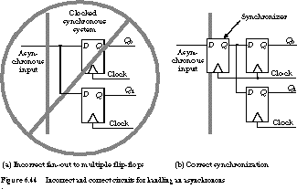
Sometimes asynchronous inputs cannot be avoided-for example, when a signal must pass from the outside world into the synchronous system. An example might be a reset signal, triggered by an operator pressing a push-button. It is particularly dangerous to fan out an asynchronous input to many points in the clocked system: if the input changes close to the clock event, it may be seen at some flip-flops but not others, leading to an "impossible" state.An incorrect circuit for handling an asynchronous input is shown in Figure 6.44(a).

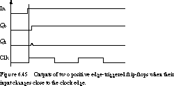
Two positive edge-triggered D flip-flops are driven by the same asynchronous input. You would expect both devices to hold the same state, yet because of different wiring and other internal delays, one flip-flop is set while the other remains reset. The assumption that both flip-flops hold the same state is now invalid. The timing waveform in Figure 6.45 tells the sad tale.

A better way to deal with an asynchronous signal is to synchronize it to the clocked system. This synchronization is accomplished by placing a single D flip-flop between the input source and the rest of the system. The proper circuit is shown in Figure 6.44(b). The flip-flop's output Q will change only in relation to the clock and can be properly fanned out and distributed to other points in the circuit in a synchronous -manner.
6.4.3 Metastability and Synchronizer Failure
What if the setup and hold times of the synchronizer flip-flop are not met by the asynchronous signal? Under such conditions, the output of the synchronizer is undefined.Normally, we minimize this problem by choosing the synchronizer flip-flop from the fastest available logic family, with the shortest possible setup and hold times. Unfortunately, the problem cannot be eliminated completely. The behavior of this flip-flop is worse than unpredictable: it can result in input values injected into the system that cannot be interpreted as either a 1 or a 0. Figure 6.45 gives a hint of this: Q1 exhibits a partial transition that falters back to 0. This "in-between" voltage is called the metastable state. Under the right
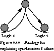
(or wrong) conditions, the flip-flop can hang in this state indefinitely, a so-called synchronizer -failure. An Analogy for Understanding Metastability Figure 6.46 provides a useful analogy for describing the nature of synchronizer failure. The states of the flip-flop are represented by two flat regions separated by a steep slope. The flat parts represent the stable states, logic 0 and logic 1. For the purpose of this analogy, we will represent the state of the flip-flop by a ball in one plateau or the other. To change the state, energy must be exerted to push the ball up and over the slope to the other side.

When setup and hold time constraints are met, there is sufficient energy to cause the state change. If these constraints are not met, three cases are possible, two that yield acceptable behavior and one that does not. In the first case, there isn't enough energy to get the ball over the summit, and it rolls back-the state is not changed. In the second case, the energy might be just enough to get the ball over the top-and the state changes from 0 to 1. Both of these are acceptable outcomes. However, there is a small probability that just enough energy is imparted that the ball can be pushed up the slope but remains tottering at the top, not able to return to one or the other of the stable states. This is the metastable state.
Theoretically, a flip-flop can remain in the metastable state. However, thermal disturbances and asymmetries in signal delays within the transistor-level implementation of the flip-flop usually make it settle in one state or the other in some period of time.

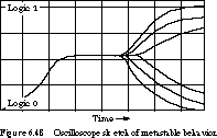
Figure 6.47 shows a circuit with its data input and clock input tied together, a perfect circuit in which to violate setup constraints. A typical trace from an oscilloscope is shown in Figure 6.48.

Even though a stable state is usually obtained (after a potentially long delay), this can still cause a system failure if the flip-flop has not left the metastable state by the end of the system's clock period.
Reducing the Chance of Synchronizer Failure The only way to recover from synchronizer failure is to reset the entire circuit. While the probability of synchronizer failure can be made small, it can never be eliminated as long as there are asynchronous inputs.
One way to reduce the probability of synchronizer failure is to lengthen the system's clock period. This gives the synchronizer flip-flop more time to make its decision to enter a stable state. The longer the clock period is stretched, the lower the probability of failure. Unfortunately, this is not an adequate solution for high-performance systems in which a short clock period is critical.
A second strategy places two synchronizers in series between the asynchronous input and the rest of the synchronous system. Both flip-flops must be metastable before the synchronization fails, an event with low probability.
A third strategy does away with the clock altogether and follows a timing strategy that is independent of the speed of the individual circuits. We examine this intriguing approach to digital design in the next section.
[Top] [Next] [Prev]