39.
1. (Moore Machine) Figure 12.1 gives a Moore state diagram for implementing the simple CPU. Figure 12.2 showed the waveforms for the memory interface, to demonstrate the correct execution of a memory read operation in the instruction fetch states. Repeat this analysis for the state sequence OD, ST0, ST1, IF0 to verify that the interface signals correctly handle a memory write operation. Draw a timing diagram similar to Figure 12.2 labeled by the current state and including the waveforms for the memory address bus, memory databus, request, and read/write signals. Annotate the waveform with comments about the arrival of the appropriate data in the MAR and MBR registers.
2. (Synchronous Mealy Machine) Section 12.1.2 described a strategy for constructing a synchronous Mealy machine by placing flip-flops between the inputs and the next-state logic. Assume that the state diagram of Figure 11.23 has been implemented as a synchronous Mealy machine in which the memory Wait signal is delayed by a synchronizing flip-flop. Verify that the memory interface operates correctly by drawing timing diagrams for all control signals asserted by the instruction fetch states. Include in your diagram the Wait signal as it leaves the memory subsystem and Wait' as it is delayed by the synchronizing flip-flop.
3. (Horizontal Branch Sequencer) Figure 12.22 gave a block diagram for a horizontal branch sequencer. Draw a complete schematic showing how this organization can be used to implement a four-way branch sequencer with a 4-bit state register. Show the data connections between the ROM outputs and the horizontal multiplexer inputs and the control connections between the a and b multiplexers and the horizontal multiplexers' select inputs.
4. (Classical FSM Implementation) Write the truth table for a pure ROM and state register implementation of the state diagram in Figure Ex12.4.
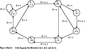
5. (Hybrid Jump Counter) Draw a schematic diagram for the state diagram of Figure Ex12.4 using a hybrid jump counter. Use a 74163 counter as the state register and multiplexers to implement the CNT, ![]() , and
, and ![]() signals. Show the contents of any ROMs you use in your implementation.
signals. Show the contents of any ROMs you use in your implementation.
6. (Jump Counter) Given the state diagram in Figure Ex12.6, draw a circuit schematic that implements the state diagram as a hybrid jump counter.
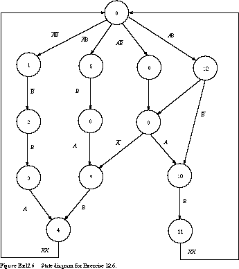
Note that any input combinations not shown on transitions in the state diagram imply that the machine remains in its current state. Also, assume that the state register is implemented by a 74163 counter and that CLEAR dominates LOAD, which dominates COUNT. The finite state machine has two inputs, A and B. Show the contents of the next-state ROM and use 16-to-1 multiplexers to compute the CLR, CNT, and LD -signals.
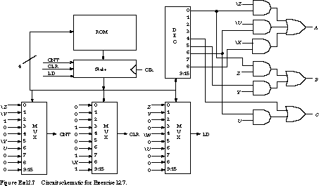
7. (Jump Counter) Given the schematic of a jump counter in -Figure Ex12.7 for a controller with input signals labeled U, V, W, X, Y, Z and output signals labeled A, B, C, derive the associated state diagram. The contents of the jump state ROM are as follows:
   Address

  Contents


  Address

  Contents

  0000

  0101


  1000

  0000

  0001

  0100


  1001

  0000

  0010

  0000


  1010

  0000

  0011

  0000


  1011

  0000

  0100

  0111


  1100

  0000

  0101

  0000


  1101

  0000

  0110

  1000


  1110

  0000

  0111

  0000


  1111

  0000
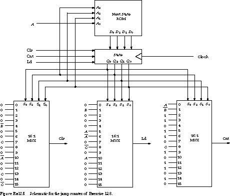
8. (Jump Counter) Given the schematic of a jump counter in -Figure Ex12.8 for a controller with input signals A, B, C, derive the associated state diagram. The contents of the jump state ROM are as -follows:
| Address | Contents | | Address | Contents |
|---|---|---|---|---|
| 0000 | 1011 | | 1000 | 1111 |
| 0001 | 1110 | | 1001 | 1001 |
| 0010 | 0101 | | 1010 | 1101 |
| 0011 | 1000 | | 1011 | 0011 |
| 0100 | 0000 | | 1100 | 1010 |
| 0101 | 1001 | | 1101 | 0011 |
| 0110 | 0010 | | 1110 | 0000 |
| 0111 | 1111 | | 1111 | 0011 |
Recall that the counter's CLR input dominates the LD, which in turn dominates the CNT.
(Branch Sequencers) 
Figure Ex12.9(a) gives a block diagram of a four-way branch sequencer implementation of a finite state machine. The machine has four inputs (A, B, C, D) and four outputs (W, X, Y, Z), and the contents of the ROM are shown in Figure Ex12.9(b).
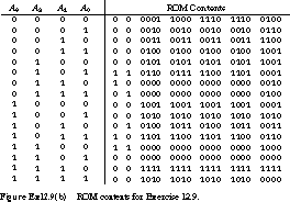
Draw the state diagram corresponding to this finite state machine implementation.
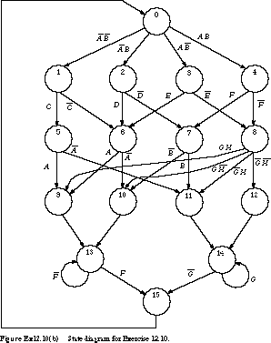
10. (Branch Sequencers) The block diagram of Figure Ex12.10(a) shows a four-way branch sequencer implementation of a finite state machine.
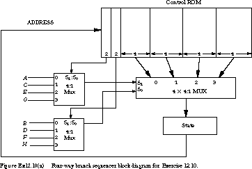
The machine has eight inputs: A, B, C, D, E, F, G, H. Implement the state diagram of Figure Ex12.10(b), by creating a table for the control ROM's contents.
11. (Horizontal Microprogramming) Reimplement the controller of Figure Ex12.4 using a horizontal microprogramming approach for the next-state logic. You are restricted to an eight-word ROM, but you choose the ROM width and the external hardware needed to select the correct next state. Describe your ROM layout and its contents, and draw a schematic of your controller.
12. (Controller State Diagram) In the previous chapter, Exercises 11.6 through 11.9 stepped you through the design of a data-path for a simple processor with 10 instructions (ADD, AND, COMP, INC, RSR, ASR, XFER, LD, ST, BRN). Using your multiple-bus solution to Exercise 11.8, do the following:
Develop the Mealy state diagram for this processor. Assign register transfer operations appropriate for your data-path to the state transition arcs.
Develop the Moore state diagram for this processor. Assign register transfer operations appropriate for your data-path to each state in the diagram.
13. (Classical State Machine Implementation) For the state diagrams derived in Exercise 12.12, tabulate the ROM contents necessary to implement the machine.
14. (Time State Implementation) Using your Mealy state diagram from Exercise 12.12, show how to implement the machine using the time state approach. Note that the time state FSM may be somewhat more complicated because of the multiple-step instruction fetch process for this instruction set.
15. (Jump Counter Implementation) Using your Mealy state diagram from Exercise 12.12, show how to implement the machine using the hybrid jump counter approach. You may assume that multiplexers with very large numbers of inputs and decoders with very large numbers of outputs are available as single components. Describe the jump state ROM contents, the multiplexer inputs, and the Boolean logic equations for your microoperations.
16. (Branch Sequencer) Using your Moore state diagram from -Exercise 12.12, show how to implement the machine using a -horizontal branch sequencer approach. Modify the state diagram to reflect your limitation on state fan-out. How are the input -conditions organized? Show your ROM organization and tabulate its contents.
17. (Horizontal Microcode) Using your solution to Exercise 12.16 as a starting point, describe how you can encode the microoperation outputs to reduce the width of the control ROM.
18. (Vertical Microcode) Starting with the microcode format presented in Section 12.5.2, describe how to modify it for your data-path and the processor state machine from Exercise 12.12. Tabulate the vertical microcode to implement the instruction set.
19. (Controller Implementation) In the last chapter, Exercise 11.14 described a 16-operation instruction set for a stack-based -computer.
Develop the Mealy state diagram for this processor. Assign register transfer operations appropriate for your data-path to the state transition arcs.
Develop the Moore state diagram for this processor. Assign register transfer operations appropriate for your data-path to each state in the diagram. Exercise 11.15 let you choose between a Mealy and a Moore state diagram for this processor controller. In this exercise and the ones to follow, we will need both methods.
20. (Classical State Machine Implementation) For the state diagrams derived in Exercise 12.19, tabulate the ROM contents necessary to implement the machine.
21. (Time State Implementation) Using your Mealy state diagram from Exercise 12.19, show how to implement the machine using the time state approach.
22. (Jump Counter Implementation) Using your Mealy state diagram from Exercise 12.19, show how to implement the machine using the hybrid jump counter approach. Assume that you can use multiplexers with very large numbers of inputs and decoders with very large numbers of outputs as single components. Describe the jump state ROM contents, the multiplexer inputs, and the Boolean logic equations for your microoperations.
23. (Branch Sequencer) Using your Moore state diagram from -Exercise 12.19, show how to implement the machine using a -horizontal branch sequencer. Modify the state diagram to
reflect your limitation on state fan-out. How are the input con-ditions organized? Show your ROM organization and tabulate
its contents.
24. (Horizontal Microcode) Using your solution to Exercise 12.23 as a starting point, describe how you can encode the microoperation outputs to reduce the width of the control ROM.
25. (Vertical Microcode) Starting with the microcode format presented in Section 12.5.2, describe how to modify it for your data-path and the processor state machine from Exercise 12.19. Tabulate the vertical microcode to implement the instruction set.
[Top] [Next] [Prev]
This file last updated on 07/16/96 at 04:34:26.
randy@cs.Berkeley.edu;
- Enterprise Application Integration: New Solutions for a Solved Problem or a Challenging Research Field?
- Context Management of ERP Processes in Virtual Communities
- Healthcare Information: From Administrative to Practice Databases
- A Hybrid Clustering Technique to Improve Patient Data Quality
- Relevance and Micro-Relevance for the Professional as Determinants of IT-Diffusion and IT-Use in Healthcare