36.
12.4 Branch Sequencers
In a classical finite state machine, the next states are explicitly computed as output functions of the machine. One straightforward strategy is to place the bits representing the next state in a ROM addressed by the current state and the inputs. The problem with this approach is that the ROM doubles in size for each additional input.The jump counter represents a trade-off between ROM size and external circuitry. Only jump states are placed in ROM. In a pure jump counter, the ROM is addressed only by the current state. Even the hybrid approach typically selects a small subset of the inputs to form part of the ROM address. Other machine outputs are formed by logic that combines the decoded state and the processor's inputs.
Our next organization is called a branch sequencer. It stands between the two extremes of a ROM-based classical state machine implementation and the jump counter. The next states are stored in a ROM, but each state is constrained to have only a limited number of next states, which is always a power of 2.
Since it is rarely the case that the finite state machine needs to see all of its inputs to determine the next state in any given state, only a
(preferably small) subset of the inputs must be examined. The idea is to use some external logic to select the appropriate input subset, determined by the machine's current state, to use as part of the ROM address. The ROM word at this address will contain the machine's next state. In return for a small amount of external hardware, the size of the ROM can be dramatically reduced.12.4.1 Organization of a Branch Sequencer
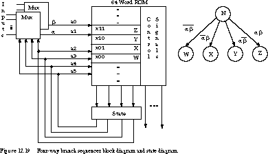
Example Four-Way Branch Sequencer Figure 12.19 shows the structure of a 22 or four-way branch sequencer implementing a Mealy controller. The high-order bits of the ROM address are formed by the current state, the low-order bits by the values of the two inputs a and b. Thus, each state has four possible next states. If a given state has only one next state, the same value is placed in all four of the ROM words dedicated to storing its next state and outputs.

Notice that the address bits a and b are driven by multiplexer outputs. The state selects among the inputs the particular two-input subset that determines the machine's next state.
As an example, consider the Mealy state machine for the simple CPU (Figure 11.23). The inputs to the machine are the Wait signal, the high--order bit of the AC, and the two IR op code bits. In the operation decode state, OD, only the IR bits need to be examined to determine the next state. In the state that executes the BRN instruction, the machine looks only at AC<15>. Many of the other states need only test the Wait signal. No state needs access to more than two of the four possible inputs.
Generalization of the Branch Sequencer It is possible to construct a 2N-way branch sequencer by simply using N selected input signals to form part of the ROM address. A four-way branch sequencer is an appropriate structure for our example processor state machine, because no states contain a multiway branch to more than four next states. A different state diagram might require a higher degree of branching.
Of course, there is a trade-off between the degree of the multiway branch the implementation supports, the size of the ROM, and the number of states in the state machine. Consider a machine with a single 16-way branch in its state diagram but many four-way branches. The 16-way branch sequencer requires four input selectors, but the four-way sequencer needs only two. This machine could be implemented more economically by replacing the single 16-way branch with multiple four-way branching states. The ROM for the four-way sequencer is likely to be half the size of that for the 16-way sequencer.
The Simple CPU Implemented with a Branch Sequencer

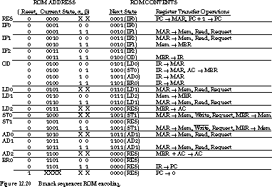
Figure 12.20 shows the ROM programming for the Mealy processor controller. The address is formed from the Reset signal, the current state (4 bits), and the conditional inputs a and b. Including Reset in the address doubles the size of the ROM, but this is the easiest way to implement the reset function. You can also use methods that explicitly clear the state flip-flops.
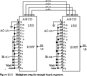
The a and b multiplexers are wired so that IR<15> and IR<14> are connected to the inputs selected by state 4 (OD). Wait is wired to both multiplexers for selector inputs 1, 2, 3, 6, 9, and 11, the states in which the signal needs to be examined. AC<15> is connected to both of the muxes' input 13. The multiplexer configurations are shown in Figure 12.21.

We can make two immediate observations about the structure of this controller. First, relatively few states use the controller's ability to support four-way next-state branches. This is no surprise, since only the operation decode state is more than two-way. Typically the wide branchiness is needed only at the decode step(s). Since each input bit doubles the size of the ROM, this illustrates how wasteful it is to include all of the inputs in the ROM address.
Second, there are many fewer inputs than states. In this case, we have four inputs but (approximately) 16 states. Since the state machine looks at only three different sets of inputs (IR<15>/IR<14>, AC<15>, and WAIT), it seems like overkill to make use of 16-to-1 multiplexers on the a and b signals. This leads us to the next variation on the branch sequencer.
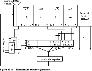
Horizontal Branch Sequencer Organization At the expense of some additional multiplexers, we can replace the tall thin ROM of Figure 12.19 with a short fat ROM, as shown in Figure 12.22.

There are two fundamental differences. First, the multiplexers are controlled by encoded signals output from the ROM rather than directly by the state. You should notice that these encoded signals are a function solely of the state, since the state bits alone form the ROM address. This also implies that the implementation of Figure 12.22 is a Moore machine.
Second, the four possible next states are laid out horizontally within the ROM rather than in four sequential ROM words of shorter length. If the state machine has a large number of states but relatively few inputs, the multiplexer control bits embedded in the ROM make it possible to use multiplexers with fewer inputs to control the next-state logic.
Let's look at the simple CPU's state machine as an example of this controller organization. Using this approach, we can replace the vertical 16-to-1 multiplexers with 2-to-1 multiplexers. The a multiplexer has IR<15> and AC<15> as its inputs; the b multiplexer's inputs are IR<14> and Wait. Each of the multiplexers is controlled by a single bit in the ROM word. When the machine is in the OD state, the a and b multiplexer control bits are set to select IR<15> and IR<14>, respectively. The horizontal multiplexers select A0 if both bits are 0; A1 if IR<15> = 0, IR<14> = 1; A2 if IR<15> = 1, IR<14> = 0; and A3 if both bits are 1.
When the machine is in its execution state for the BRN instruction, the multiplexer control bits are set to select AC<15> from the a multiplexer. The b multiplexer bit is a don't care, so A0 and A1 should contain the same next-state bits, as should A2 and A3. A0/A1 is selected if AC<15> = 0; otherwise A2/A3 is selected.
A similar argument explains how the multiplexers work when the state needs to examine the Wait signal. In this case, the a multiplexer is the don't care and the b multiplexer is set to select Wait. A0 and A2 should contain the same value, as should A1 and A3. If Wait is asserted, then A1/A3 determines the next state. Otherwise it is set to the state specified by A0/A2.
The horizontal next-state scheme is advantageous in large and complex controllers with many-way branches. Adding length to the ROM word usually requires fewer bits than increasing the number of ROM words. Once again, let's consider the simple CPU state machine. Its controller has 14 register transfer outputs. With the four next-state bits, the ROM contains 64 by 18 bits or 1152 ROM bits (we assume that reset is handled by external logic). The horizontal method requires the same 14 control bits, plus four 4-bit next states as well as two additional multiplexer control bits. This yields a total ROM word length of 32 bits. But since the horizontal organization requires only 16 ROM words, the total number of ROM bits is much smaller: just 512 bits. In the next subsection, we will examine the trade-offs between vertical and horizontal ROM organizations more closely.
[Top] [Next] [Prev]