3.5 The ProducerConsumer Problem
|
| < Day Day Up > |
|
3.5 The Producer/Consumer Problem
3.5.1 Problem Description
The producer/consumer problem can be stated as follows: A buffer with a finite number of slots for data is created to hold data created by a producer. In our problem, the buffer will be implemented using a circular array called a bounded buffer. The producer will simply create integers from 1 to 10 and send them to the buffer. The buffer will store them in the next empty slot. The consumer will retrieve the 10 integers from the buffer and print them to the screen. The buffer will have the ability to store only three items, so it is possible for the producer to create more items than the buffer can hold before the consumer can retrieve an item. When this happens, the producer must wait for the consumer to take an item from the buffer to create a free slot before sending another item. Likewise, the consumer could retrieve all the items already created by the producer, and there would be no items in the buffer to retrieve. When this happens, the consumer must wait until the producer creates another item and adds it to the buffer before continuing to retrieve items from the buffer.
3.5.2 Write a Short Description of the Problem
The first thing that needs to be done is to write a short description of the problem. This step is probably the most important, and the one most frequently overlooked. Often programmers start designing their programs before they have a good grasp of the problem to be solved. This leads to the creation of many objects and methods that have no relationship to the problem to be solved simply because they are somehow referred to or implied in the problem definition. In this example, the problem statement is obvious. Create a producer that creates data and a consumer that uses the data and have them coordinate using a bounded buffer.
3.5.3 Define the Objects and Relationships
Looking at the problem definition, we find that the nouns are a producer, a consumer, a buffer, and a circular array with three slots to hold data. The producer, consumer, and buffer are the obvious objects, with the circular array being an attribute of the buffer. Of these three objects, the producer and consumer do things (produce and consume data) and are active. The buffer simply stores and retrieves data requested by the producer and consumer and is passive. The next step is to look at the verbs that describe the active objects. The producer is described as creating a number and sending it the buffer. The consumer is described as retrieving a number from the buffer and printing it to the screen. This is sufficient detail to describe the activities of both of these objects. These objects simply implement "for loops" to send and retrieve the data. The buffer object responds to two requests. The first is to take an item from the producer and add it to the circular array. The second is to take an item from the buffer and give it to the consumer; therefore, the buffer will have two methods: an addToBuffer and a takeFromBuffer.
3.5.4 Design and Implement the Active Objects
The active objects, the producer and consumer, are now implemented. The pseudo-code for the producer is simply:
for (I = 1 to 10) Send an item to the buffer
The pseudo-code for the consumer is just the mirror of the producer code:
for (I = 1 to 10) Get an item from the buffer
The code for these is shown in Program3.1 (Exhibits 1 and 2). Note that in all the problems in this chapter, the active objects are always threads; therefore, the actions that define these objects are stated in the run method, which is where the thread begins running.
Exhibit 1: Program3.1a: Producer Class
public class Producer implements Runnable { private BoundedBuffer bb;//BoundedBuffer used to coordinate //with the consumer /** * Constructor that saves the shared BoundedBuffer object */ public Producer(BoundedBuffer bb) { this.bb = bb; } /** * Producer thread, which creates values and passes * them to the BoundedBuffer */ public void run() { int value; for (int i = 0; i < 10; ++i) { System.out.println("Producer adding value = "+ i); bb.addToBuffer(i); } } } Exhibit 2: Program3.1b: Consumer Class
public class Consumer implements Runnable { private BoundedBuffer bb;//BoundedBuffer used to coordinate //with the producer /** * Constructor that saves the shared BoundedBuffer object */ public Consumer(BoundedBuffer bb) { this.bb = bb; } /** * Producer thread, which creates values and passes * them to the BoundedBuffer */ public void run() { for (int i = 0; i < 10; ++i) { System.out.println("Consumer got value = "+ bb.takeFromBuffer()); } } } One additional comment must be made about these objects. Both of these active objects must share the BoundedBuffer object, so the BoundedBuffer must be created outside of these objects and somehow passed into the objects. The constructors for these objects are used to accomplish this. The BoundedBuffer will first be created in the controlling object and then passed to these objects and stored when the objects are created. This is discussed further in Section 3.5.7.
3.5.5 Design the Passive Object (Components)
The next step is to design the passive object, the buffer. The buffer has two methods that allow active objects to use its services. The first method, addToBuffer, allows an object to add items to this buffer, and the second method, takeFromBuffer, allows an object to remove items from this buffer. These methods do not simply perform tasks for the active objects when their methods are called, as is normally the case with function calls in procedural languages. Instead, passive objects maintain a state across the various invocations of their methods. This state allows them to maintain a flow of events as the methods of the object are used. In the producer/consumer problem, the buffer can be in one of three states: The buffer can be EMPTY, with no items in any of the slots; the buffer can be FULL, with items in all of the slots; or the buffer can be AVAILABLE, with some slots holding data and some slots being empty.
The flow within a passive object is controlled by the state of that object. In the producer/consumer problem, when the object is first created, the state of the object will be EMPTY, as no data has been added to the buffer. When the buffer is EMPTY, no calls to takeFrom-Buffer are allowed, as no data is available in the buffer to be removed. From the EMPTY state, a call to addToBuffer is allowed, which causes a change of state to AVAILABLE, thus allowing calls from both take-FromBuffer and addToBuffer. If two items are already in the buffer, adding a third item causes the buffer to be filled and changes the state of the buffer from AVAILABLE to FULL. A FULL buffer allows calls from takeFromBuffer, but not addToBuffer, as no more space is available to store an item.
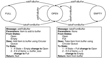
It should be obvious that trying to describe the behavior of passive objects using prose, as above, is difficult. Because methods can only show procedural flow, the methods in a passive object are inadequate to represent the overall design of the passive object. Fortunately, passive objects are easy to design and represent using a technique called state diagrams. To model a passive object using a state diagram, the states are represented as nodes in the diagram and methods as transitions between those states. Exhibit 3 shows the design of the buffer as a state diagram. The reader should follow the logic and be convinced that the design does match the description provided here and implements the logic needed for the buffer.
Exhibit 3: State Diagram for Producer/Consumer Problem
State diagrams have been used for a long time to describe the behavior of programs. For example, they have been used in hardware design to describe the behavior of hardware components, and are part of the Unified Modeling Language (UML). The way that state diagrams are used to design the components does not differ greatly from the ways in which they are used for hardware design or Object Oriented Design (OOD), but the way they are actually implemented is different. For more in-depth discussions of state diagrams, the reader should refer to the Further Reading section of this chapter.
At the bottom of Exhibit 3 are two tables that describe the methods that are used as transitions. These tables summarize information about the methods and provide additional information not contained in the state diagram. The sections in these tables are:
-
The states from which execution of each method is valid
-
The method's parameters
-
The activity that is to be accomplished by the method
-
Any data that should be returned from this method
-
The conditions that cause transitions to occur when the method is executed
While the state to be transitioned to is given by the arcs in the state diagram, the conditions that cause this transition are not explicitly given in the diagram and so are specified here. From this summary, all the information needed to implement the passive objects is available, and the rules for implementing them are given in the next section.
3.5.6 Implementing Passive Objects
Implementing passive objects can be a daunting task for programmers who are new to concurrent programming, but, if a state diagram has been produced that describes the passive object, then the translation from the state diagram to an actual working implementation of the object is mechanistic. To implement passive objects we employ a data structure called a monitor. Monitors can be thought of as objects where only one thread can be executing inside of any method at any given time. Monitors can be created in Java by making all the methods of an object synchronized and putting in place guards (method pre-conditions) that allow entry to the methods to be controlled by the state of the object. Method post-conditions can then be implemented to model the transitions to other states. The rest of this section shows how to write methods to implement this behavior.
The first step in implementing the state diagram is to have some combination of one or more variables that are private to this object and represent the state of the object. In the simplest case, as in our producer/consumer problem, the state is represented by a single variable. Constants are defined that specify the valid values for that state variable. For example, in the bounded buffer we can define the states for the buffer using the following declarations:
private static final int EMPTY = 0; private static final int AVAILABLE = 1; private static final int FULL = 2; private int state = EMPTY;
The second step in the translation of the state diagram involves dividing the method into sections of code corresponding to the sections in the tables at the bottom of the state diagram. Each method has the following: (1) a name and parameters corresponding to the first two sections in the tables; (2) a pre-condition, or guard, which prevents the method from being executed unless the object is in the correct state; (3) the code that performs any activities specified in the table; (4) any post-condition processing to check if the state of the object must be changed as a result of the execution of the method; and (5) return of any specified data.
Other than the sections of the method that do the pre-condition and post-condition processing, the implementation of the method is straightforward. Therefore, the only parts of the method that will be covered in more detail in this section are the pre-condition and post-condition processing.
Pre-conditions (or guards) protect the method from being executed when the object is not in a valid state. For example, if the buffer is EMPTY, the guard will force a thread calling addToBuffer to wait until another thread has completed a call to takeFromBuffer to create an open slot.
All pre-condition code has a similar format. The generic format for the pre-condition code used here is as follows:
while(! ((state = = validState1 || state = = validState2))){ wait(); } The values of validState1 and validState2 are states from which arcs emanate in the state diagram and are the states of the object from which this method can execute. If the object is in a correct state to execute this method, then the while statement is not executed and the thread continues to execute the method. If the object is not in a correct state, the wait statement is executed, and the thread calling this method will suspend, freeing the object to be used by other threads. To implement a pre-condition, a programmer need only place the valid states for executing the method in the "if" block above. Note the format of the pre-condition. The current state is compared with each valid state, and these comparisons are then "or'ed" together. The result of the "or'ed" statements is then negated.
Post-conditions work in conjunction with the pre-conditions to ensure that the monitor maintains a valid state. In post-condition processing, the method checks to see if some condition has been reached that causes the object to change to a new state. If the object does not change state, the method does nothing in the post-condition. However, if the state is changed (i.e., the state variable is set to a new value), then notifyAll must be called. This is done because another thread may be currently waiting on the monitor. If the state has not changed, the waiting threads do not need to check the status of the monitor as it will not have changed and the waiting threads will always have to do another wait. However, if the state has changed, it is possible that a thread waiting on the monitor will now be able to continue, so the notifyAll call allows all waiting threads to wake up and check the status of the monitor to determine if they can now continue.
The generic format of the post-condition process is:
if (condition1 = = true) { state = newState_1; notifyAll(); } else if (condition2 = = true) { state = newState_2; notifyAll(); } Note the lack of a final "else" condition; if no state change occurs, any waiting threads do not need to be notified.
The procedure for implementing each method in a monitor, given a state diagram, can be summarized as follows:
-
Define a variable or variables to represent the state of the monitor and possibly constants to represent each of the valid states of the monitor.
-
Write the declaration of the method, including the synchronized keyword as part of the declaration.
-
Implement any pre-conditions for the method using the procedure outlined above.
-
Implement the code to achieve the function defined for the method.
-
Implement any post-condition processing for the method using the procedure outlined above.
-
Return any indicated data from the method.
The implementation of the buffer monitor using these rules is shown in Exhibit 4 (Program3.1c).
Exhibit 4: Program3.1c: Implementation of the BoundedBuffer Object
public class BoundedBuffer { //Variables need to define the circular queue used as the //buffer. private int values[]; private int firstItem = 0; private int lastItem = 0; private int numberOfItems = 0; private int bufferSize; //Variables to maintain the monitor state public static final int EMPTY = 0; public static final int OPEN = 1; public static final int FULL = 2; private int bufferState = EMPTY; //Constructor for the BoundedBuffer. Note that the size of the //buffer is set here based on the parameter bufferSize. public BoundedBuffer(int bufferSize) { this.bufferSize = bufferSize; values = new int[bufferSize]; } /** * addToBuffer adds the item in the parameter to the buffer. */ public synchronized void addToBuffer(int value) { //Pre-condition processing (method guard) while(! ((bufferState = = EMPTY) || (bufferState = = OPEN))) { try { wait(); } catch (InterruptedException e) { } } //Processing done to add item to buffer System.out.println("item "+ value + "added to buffer"); values[lastItem] = value; lastItem = (lastItem + 1)% bufferSize; numberOfItems = numberOfItems + 1; //Post-condition processing to change states if ((bufferState = = OPEN) && (numberOfItems > = bufferSize)) { bufferState = FULL; notifyAll(); } else if (bufferState = = EMPTY) { bufferState = OPEN; notifyAll(); } } /** * takeFromBuffer retrieves and removes an item from the buffer. */ public synchronized int takeFromBuffer() { int value; //Pre-condition processing (method guard) while(! ((bufferState = = FULL) || (bufferState = = OPEN))) { try { wait(); } catch (InterruptedException e) { } } //Processing done to take item from buffer value = values[firstItem]; System.out.println("item "+ value + "taken from buffer"); firstItem = (firstItem + 1)% bufferSize; numberOfItems = numberOfItems - 1; //Post-condition processing to change states if ((bufferState = = OPEN) && (numberOfItems < = 0)) { bufferState = EMPTY; notifyAll(); } else if (bufferState = = FULL) { bufferState = OPEN; notifyAll(); } //Return the value taken from the buffer. return value; } }
3.5.7 Implementing the Controlling Object
Now that the pieces of the program are created, they need to be tied together to create a program. This is done in a control object. A control object is an object that controls the overall creation and linkage of the objects used in the program. It does not control the individual active or passive objects. For example, consider Exhibit 5 (Program3.1d). This program creates the passive BoundedBuffer object and then creates the objects for the threads, registering the shared BoundedBuffer objects with each of these active objects by passing the passive object to their constructors. Threads are then created and started for each of the active objects. The most interesting feature of the controlling object is that it does not really contain any procedural code. All of the code in this object involves declaring object and threads or starting a thread. The control for the program resides entirely in the run methods of the active objects.
Exhibit 5: Program3.1d: Implementation of the Producer Consumer Control Object
public class ProducerConsumer { public static void main(String args[]) { BoundedBuffer bb = new BoundedBuffer(3); (new Thread(new Producer(bb))).start(); (new Thread(new Consumer(bb))).start(); } } |
| < Day Day Up > |
|
EAN: 2147483647
Pages: 162