Fiber Distributed Data Interface Networks
| < Day Day Up > |
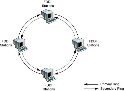
| A typical Fiber Distributed Data Interface (FDDI) network is based on a dual counter-rotating ring, as illustrated in FIGURE 5-2. Each FDDI station is connected in sequence to two rings simultaneously a primary ring and a secondary ring. Data flows in one direction on the primary ring and in the other on the secondary ring. Figure 5-2. Typical FDDI Dual Counter-Rotating Ring
The secondary ring serves as a redundant path. It is used during station initialization and can be used as a backup to the primary ring in the event of a station or cable failure. When a failure occurs, the dual ring is "wrapped" around to isolate the fault and to create a single one-way ring. The components of a typical FDDI network and the failure recovery mechanism are described in more detail in the following sections. FDDI StationsAn FDDI station is any device that can be attached to a fiber FDDI network through an FDDI interface. The FDDI protocols define two types of FDDI stations:
Single-Attached StationA SAS is attached to the FDDI network through a single connector, called the S-port. The S-port has a primary input (Pin) and a primary output (Pout). Data from an upstream station enters through Pin and exits from Pout to a downstream station, as shown in FIGURE 5-3. Single-attached stations are normally attached to single-and dual-attached concentrators as described in "FDDI Concentrators" on page 134. Figure 5-3. SAS Showing Primary Output and Input
Dual-Attached StationA DAS is attached to the FDDI network through two connectors, called the A-port and the B-port, respectively. The A-port has a primary input (Pin) and a secondary output (Sout); the B-port has a primary output (Pout) and a secondary input (Sin). The primary input/output is attached to the primary ring and the secondary input/output is attached to the secondary ring. The flow of data during normal operation is shown in FIGURE 5-4. Figure 5-4. DAS Showing Primary Input and Output To complete the ring, you must ensure that the B-port of an upstream station is always connected to the A-port of a downstream station. For this reason, most FDDI DAS connectors are keyed to prevent connections between two ports of the same type. FDDI ConcentratorsFDDI concentrators are multiplexers that attach multiple single-attached stations to the FDDI ring. An FDDI concentrator is analogous to an Ethernet hub. The FDDI protocols define two types of concentrator:
Single-Attached ConcentratorA SAC is attached to the FDDI network through a single connector, which is identical to the S-port on a single-attached station. It has multiple M-ports to which single-attached stations are connected, as shown in FIGURE 5-5. Figure 5-5. SAC Showing Multiple M-ports with Single-Attached Stations Dual-Attached ConcentratorA DAC is attached to the FDDI network through two ports the A-port and the B-port, which are identical to the ports on a dual-attached station. A DAC has multiple M-ports, to which single-attached stations are connected as shown in FIGURE 5-6. Figure 5-6. DAC Showing Multiple M-ports with Single-Attached Stations Dual-attached concentrators and FDDI stations are often arranged in a flexible network topology called the ring of trees. Additionally, many failover capabilities are built into the FDDI network to ensure it is robust. FDDI InterfacesSun supports two FDDI drivers for its range of SPARC platforms: the SBus driver, known as the SunFDDI/S, and the PCI driver, known as SunFDDI/P. The SBus-based and the PCI FDDI interfaces provide access to 100 mbit/s FDDI local area networks. Configuring the SunFDDI/S Adapter with TCP/IPThe Sbus FDDI driver is called nf and can be configured using ifconfig once you have established that the interface is physically present in the system and the device driver is installed. Refer to "Configuring the Network Host Files" on page 234. The rest of this section describes the configuration of individual parameters of the nf device that can be altered in the driver.conf file.
Setting the Maximum Transmission UnitSun Supports the FDDI maximum transmission unit (MTU) that has been optimized for pure FDDI networks.
Target Token Rotation TimeTarget token rotation time (TTRT) is the key FDDI parameter used for network performance tuning. In general, increasing the TTRT increases throughput and increases access delay. For SunFDDI, the TTRT must be between 4000 and 165,000 ms. The TTRT is set to 8000 ms by default. The optimum value for the TTRT is dependent on the application and the type of traffic on the network:
The TTRT is established during the claim process. Each station on the ring bids a value (T_req) for the operating value of the TTRT (T_opr) and the station with the lowest bid wins the claim. Setting the value of T_req on a single station does not guarantee that this bid will win the claim process.
Configuring the SunFDDI/P Adapter with TCP/IPThe PCI bus FDDI driver is called pf and can be configured using ifconfig once you have established that the interface is physically present in the system and the device driver is installed. Refer to "Configuring the Network Host Files" on page 234. The rest of this section describes the configuration of individual parameters of the pf device that can be altered in the driver.conf file.
Setting the Maximum Transmission UnitSun supports the FDDI maximum transmission unit (MTU) that has been optimized for pure FDDI networks.
Target Token Rotation TimeThe target token rotation time (TTRT) can also be programmed with the SunFDDI/P. A detailed explanation of the TTRT is provided above with the SunFDDI/S.
|
| < Day Day Up > |
EAN: 2147483647
Pages: 116