Sample Application
We'll now look at another example that provides a form of fault tolerance within an embedded domain. While reviewing this application, we'll also present the other consequent primitives that are available.
Fault Tolerance
In a very simple application, we'll encode rudimentary knowledge of sensor management into our rules. A redundant set of sensors exists from which one can be set as the active sensor (and thus be used by the larger system). Either of the sensors may be working (or failed), but only one may be active at any given time. If neither of the sensors is working, then neither can be active. Additionally, our mode must change to denote that a problem exists within the sensor subsystem.
In this application, it is assumed that we're operating in a blackboard architecture (see Figure 8.3). Blackboard architecture contains a number of agents that use and produce data on the blackboard. The blackboard serves as a working space where facts are communicated amongst the agents. Agents are triggered by data on the blackboard and can manipulate the data (adding, changing, or removing), which may trigger other agents to continue the work process.
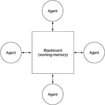
Figure 8.3: Graphical depiction of a blackboard architecture.
The blackboard architecture is interesting because it not only provides the ability for agents to communicate with one another, but also to coordinate and synchronize their activities.
Rules Definition
The rules file for our sample fault tolerance demonstration is shown in Listing 8.2. This set of rules introduces a number of new consequents (actions) that can be performed.
| |
(defrule init (true null) ; antecedent => (add (sensor-active none)) ; consequents (add (sensor-working sensor1)) (add (sensor-working sensor2)) (add (mode failure)) (enable (timer 1 10)) (print ("default rule fired!")) (disable (self)) ) ; ; Define active rule-set ; (defrule sensor-failed (sensor-working ?) (sensor-failed ?) => (delete (sensor-working ?)) ) (defrule check-active (sensor-active ?) (sensor-failed ?) => (delete (sensor-active ?)) (add (sensor-active none)) ) (defrule make-working (sensor-active none) (sensor-working ?) => (add (sensor-active ?)) (delete (mode failure)) (add (mode normal)) (delete (sensor-active none)) ) (defrule failure (mode normal) (sensor-active none) (sensor-failed sensor1) (sensor-failed sensor2) => (add (mode failure)) (delete (mode safe)) (delete (mode normal)) ) ; Use triggers to simulate timed events... (defrule trigger1 (timer-triggered 1) => (print ("Sensor 1 failure.\n")) (add (sensor-failed sensor1)) (enable (timer 2 10)) (delete (timer-triggered 1)) ) (defrule trigger2 (timer-triggered 2) => (print ("Sensor 2 failure.\n")) (add (sensor-failed sensor2)) (enable (timer 3 10)) (delete (timer-triggered 2)) ) (defrule trigger3 (timer-triggered 3) => (print ("Sensor 1 is now working.\n")) (delete (sensor-failed sensor1)) (add (sensor-working sensor1)) (enable (timer 4 10)) (delete (timer-triggered 3)) ) (defrule trigger4 (timer-triggered 4) => (print ("Sensor 2 is now working.\n")) (delete (sensor-failed sensor2)) (add (sensor-working sensor2)) (enable (timer 1 10)) (delete (timer-triggered 4)) ) | |
This example contains nine rules, but only four are actual operating rules. The first rule ( init ) in Listing 8.2 is an initialization rule. Note that the antecedent is ( true null ), which always resolves to true. This initialization rule permits us to seed the working memory with an initial set of facts (as defined by the add commands). The enable command allows us to enable a timer, which when fired can trigger another rule. We'll use timers in this example to perform simulated events from the environment. These would be events (facts) placed into the working memory from other agents operating within the environment (recall Figure 8.3). [Note: The timers used in this example are modeled after Microsoft's The Age of Kings , which uses a rules file to define the game AI.] The timer command uses two arguments, the numeric id of the timer and the number of seconds until the timer should fire (in this case, timer 1 will fire in 10 seconds). The print command is a debugging command that provides us with some visibility into the reasoning of the system. The final command in this rule, disable , is very important. It provides the ability to disable the rule from the set of available rules. This rule can then never be fired again, an obvious need for rules whose antecedents are always matched (such as the init rule).
Once the init rule has fired, the working memory will contain:
(sensor-active none) (sensor-working sensor1) (sensor-working sensor2) (mode failure)
Rule make-working would be the next rule to fire (using sensor1 as the matched parameter), leaving working memory as:
(sensor-working sensor1) (sensor-working sensor2) (sensor-active sensor1) (mode normal)
At this point, no further rules can fire and the system remains in this state until the timer fires (after 10 seconds). When a timer fires, the system simply adds the fact to working memory ( (timer-triggered 1) ). This new fact in working memory then causes the rule to fire that handles the particular timer (using the trigger event as the rule's antecedent). The event triggered by the timer simulates the failure of sensor1 , modifying working memory as follows :
(sensor-working sensor1) (sensor-working sensor2) (sensor-active sensor1) (mode normal) (sensor-failed sensor1)
Rules sensor-failed and check-active then fire, leaving working memory in the following state:
(sensor-working sensor2) (mode normal) (sensor-failed sensor1) (sensor-active none)
Finally, rule make-working fires, leaving working memory as:
(sensor-working sensor2) (mode normal) (sensor-failed sensor1) (sensor-active sensor2)
At this point, the system is operational with a working sensor from the redundant pair. The rules also provide for no working sensors with an indication of this event using the mode fact. The derivation of the remaining rule firings is left for the reader.
| Note | This example can be performed with the rules-based system application on the CD-ROM. The fault-tolerance example shown above is contained in the file |
| On the CD | The source code for the rules based system can be found on the CD-ROM at ./software/ch8/rbs/. |
EAN: 2147483647
Pages: 175