Configuring Frame Relay
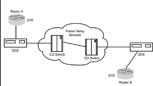
| Configuring a Cisco router to serve as a DTE (Data Terminal Equipment) device within a Frame Relay network involves configuring interfaces on the router. Table 10.6 lists the commands you must execute to configure Frame Relay on an interface. Table 10.6. Frame Relay Basic Configuration
In configurations where inverse ARP is not used to dynamically discover network protocol addresses on the virtual circuit, the frame-relay map command must be used to map the Layer 3 protocol address to the Layer 2 DLCI. Configure the frame-relay map command as follows : Frame-relay map protocol protocol-address dlci [broadcast] [cisco ietf] In this example, protocol is a supported protocol, such as IP or IPX, protocol-address is the destination protocol address, and dlci is the DLCI number used to connect to the specified protocol address on the interface. Also, broadcast (optional) forwards broadcasts to this address (although this is optional, it's usually a good idea to include it), and ietf (optional) uses the Internet Engineering Task Force (IETF) form of Frame Relay encapsulation (use this parameter when the router or access server is connected to another vendor's equipment across a Frame Relay network). Finally, cisco (optional) is the Cisco encapsulation method. NonBroadcast MultiAccessBecause Frame Relay connections are established by direct Permanent Virtual Circuits (PVCs), Frame Relay cannot support broadcast transmissions. If broadcast services are required, a router must copy the broadcast and then transmit it on each of its PVCs. The term that describes this behavior is NonBroadcast MultiAccess (NBMA). NBMA simply describes any multiaccess Layer 2 protocol that does not provide a mechanism for broadcasting messages (such as route updates between routers). For broadcast messages to be communicated in an NBMA network, each router within the network serves as a peer and is part of the same subnet. In a Frame Relay network, broadcast messages must be duplicated and then send out each PVC to each peer. SubinterfacesA single, physical serial interface can be configured with several virtual interfaces called subinterfaces . These subinterfaces can be configured on a serial line; different information is sent and received on each serial subinterface. Using subinterfaces, a single router can support PVCs to several other routers. Figure 10.6 depicts a simple Frame Relay network with subinterfaces. Figure 10.6. A simple frame relay network. Before configuring a subinterface for a Frame Relay network, the Frame Relay configuration on the physical interface must be complete. Execute the following command to create a subinterface and assign it a DLCI value: Interface type . subinterface point-to-point Frame-relay interface-dlci dlci [broadcast] In this command, type is the physical serial interface number, subinterface is the subinterface number, dlci is the DLCI number used to connect to the specified protocol address on the interface, and broadcast (optional) forwards broadcasts to this address. A common practice in choosing subinterface numbers is to use the same number as the DLCI value.
|
EAN: N/A
Pages: 155
