Understanding the Fundamentals of MLS
The first of the Cisco MLS implementations involves the use of a router on a stick. Figure 7.1 depicts the router-on-a-stick architecture. As you can see from the diagram, there are multiple hosts using two separate VLAN assignments. One segment is running on VLAN 10 and the other is running on VLAN 50. Both VLANs are connected to the same switch. The switch is then connected to a router. Here we show an external router, but an RSM provides the same functionality, just internally.
By now, you understand that for Host A on VLAN 10 to communicate to Host D on VLAN 50, packets must be routed through Router A. Because of the VLAN assignments, the switch must send the packet to the router on interface FE0/0.10. The router knows that the route to the network assigned to VLAN 50 is through interface FE0/0.50. The packet is then sent back to the switch and forwarded to Host D.
Now back to our original question. Why use layer 3 switching? You can see in Figure 7.1 that it is very inefficient to have to use a router to move a packet from Host A to Host D when they are connected to the same switch. MLS is used to bypass the router on subsequent packets of the same flow. A flow is a table entry for a specific conversation, created by using source and destination header information for layers 3 and 4. The switch caches the routing information for that particular flow to make changes to future packets. Several fields within a packet make it unique:
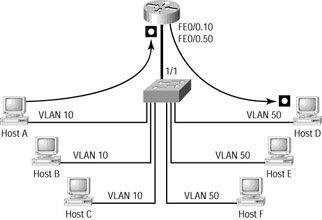
Figure 7.1: Router-on-a-stick diagram
-
Source and destination IP addresses
-
Source and destination MAC addresses
-
Type of Service (ToS)
-
Protocol type (for example, HTTP, FTP, ICMP, and so on)
These are just some of the characteristics of a packet that can be used to establish a flow. A switch can be configured to support simple flows, such as IP address to IP address, or the switch can support complex flows dealing with port and protocol information.
To summarize, we use MLS to enable the switch to forward the first packet in the flow to the router and then learn what should be done with the rest of the packets in the flow so the router doesn’t need to route them. In Figure 7.1, the switch makes the necessary VLAN and destination MAC address changes in the subsequent packets.
MLS tends to work better when the packet stream is fairly large. If a user is browsing the corporate intranet, they might be getting information from multiple servers located in various areas. If that same user is downloading a file via FTP, it is easy to see that the hundreds of fragments are all coming from the same place and going to the same place. Only the initial fragment needs to be routed; the rest of them are layer 3 switched.
For the best results, use MLS when large files are accessed or when the same type of information is accessed on a frequent basis. Users checking their e-mail every minute would be an example of an application that generates small but frequent packets.
MLS Requirements
Some Cisco Catalyst switches require additional hardware to make use of the packet header information. While the 3550 series and the 4000 series with the Supervisor IV card have on-board processing, Catalyst 6000 series switches use the Multilayer Switch Feature Card (MSFC) and the Policy Feature Card (PFC) to gather and cache header information. (You may remember that the old Catalyst 5000 switches used the NetFlow Feature Card (NFFC) to gather this information and cache it.) A detailed process, which will be discussed later in this chapter, enables switches to establish flows.
MLS requires three components to function in any network (we have already briefly discussed two of them):
-
Multilayer Switching Route Processor (MLS-RP) is a directly attached router. This can be an MLS-capable external router or an RSM installed in the switch.
-
Multilayer Switching Switch Engine (MLS-SE) is an MLS-capable switch (a 6000 with an MSFC and PFC).
-
Multilayer Switching Protocol (MLSP) is a protocol that runs on the router and enables it to communicate to the MLS-SE regarding topology or security changes.
Now that you have a basic understanding of what MLS does and what is required for MLS to function in a network, let’s get into the nitty-gritty of how it works. Throughout the rest of the chapter, you will see the preceding abbreviations many times.
MLS Procedures
We discussed the three required components of MLS. It is important to understand how they work together to enable layer 3 switching. Let’s look at a sample network topology that supports MLS.
Figure 7.2 shows a simple architecture of a router and a switch with two connected hosts on the switch. Again, the hosts have different VLAN assignments, requiring the router’s intervention to route packets. Notice that the figure depicts the main interface with two subinterfaces, FE0/0.2 and FE0/0.3. As it stands, the current topology requires that all packets sent from the client on VLAN 3 to the client on VLAN 2 be routed by the external router. If there are a large number of packets, this creates a lot of unnecessary work.
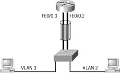
Figure 7.2: MLS example topology
MLS follows a four-step process to establish the layer 3 switching functionality. These four steps can then be broken down into more detailed processes, which will be discussed shortly. If these descriptions leave you a bit confused, the detailed explanation should clear things up. The four steps required to enable MLS are as follows:
MLSP discovery The MLS-RP uses MLSP to send hello packets out all interfaces to discover any MLS-SE devices and establish the MLS-RP/MLS-SE neighbor relationships.
Identification of candidate packets The NFFC or PFC watches incoming packets and as it forwards the packets to the router, it creates partial cache entries for them, thus identifying the packets as potential candidates for a flow. A candidate packet is one that has yet to return from the router.
Identification of enable packets The NFFC or PFC watches packets coming from the MLS-RP and tries to match them with candidate packet entries. If matches are made, the packets are tagged as enable packets and a shortcut forwarding entry is made in the CAM table. This shortcut tells the switch how to duplicate the effect of routing. Everything that the router did to the packet, the switch is now able to do.
Layer 3 switching of subsequent flow packets Incoming packets are compared against CAM table entries. If the packets match the flow criteria, the switch will take the shortcut information and make any necessary changes, and the packet is directly forwarded to the appropriate exit port for the flow.
As we said, the preceding list is an overview of the steps that must take place before packets can be switched at layer 3. We’ll discuss each step in detail next.
MLSP Discovery
Switches need routers to perform the initial route table lookup and the packet rewrite. This dependency requires that MLS adjacencies are established between the switch and the router. This is accomplished by using MLSP.
Initially, the router, or MLS-RP, sends hello packets containing all the MAC addresses and VLANs configured for use on the router. These messages are sent every 15 seconds to a layer 2 multicast address of 01-00-0C-DD-DD-DD. This is the address for the CGMP process on a Cisco switch. CGMP is covered in detail in Chapter 8, “Understanding and Configuring Multi– cast Operation,” and Chapter 9, “Quality of Service (QoS).” The intended recipients of these hello packets are the MLS-SE devices on the network.
When an MLS-SE receives the information, it makes an entry in the CAM table of all the MLS-RP devices in the layer 2 network. Layer 2 is mentioned because MLS-SE devices are not concerned with devices that are not directly connected to layer 2 devices, such as switches. Figure 7.3 depicts the MLSP discovery process.
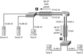
Figure 7.3: MLSP discovery
Part of the information that is stored in the CAM table after an MLSP hello packet is received is an ID called an XTAG. The following is a description of the significance and purpose of the XTAG.
XTAGs
An XTAG is a unique identifier that MLS switches use to keep track of the MLS routers in the network. All the MAC addresses and VLANs in use on the MLS-RP are associated with the XTAG value in the CAM table.
The following output is from a Catalyst 6509 with an MSFC and PFC. The show mls command was issued to provide the output:
Terry_6509> (enable) show mls Total packets switched = 4294967295 Total Active MLS entries = 85 IP Multilayer switching aging time = 256 seconds IP Multilayer switching fast aging time = 0 seconds, packet threshold = 0 IP Current flow mask is Destination flow Active IP MLS entries = 85 Netflow Data Export version: 7 Netflow Data Export disabled Netflow Data Export port/host is not configured. Total packets exported = 0 IP MSFC ID Module XTAG MAC Vlans --------------- ------ ---- ----------------- ---------- 172.16.100.5 15 1 00-d0-bc-e3-70-b1 2,3 IPX Multilayer switching aging time = 256 seconds IPX flow mask is Destination flow IPX max hop is 0 Active IPX MLS entries = 0 IPX MSFC ID Module XTAG MAC Vlans --------------- ------ ---- ----------------- ---------- 172.16.100.5 15 1 - - Terry_6509> (enable)
You can clearly see that the MSFC has been assigned the XTAG value of 1. The MSFC is a daughter card residing on the Supervisor card, which is why it uses module 15. The MSFC receives the assignment because the MSFC was configured as the MLS-RP. In this example, only one MAC address is associated with XTAG 1. However, two VLANs are associated with it.
MLS Cache
After MLS-SEs have established CAM entries for MLS-RPs, the switch is ready to start scanning packets and creating cache entries. This was described previously as the identification of candidate and enable packets.
The cache entries are made in order to maintain flow data. Flow data enables the MLS-SE to rewrite the packets with the new source and destination MAC address and then forward the packets. All of this is done without sending the packets to the router for a route lookup and to be rewritten.
Cache entries happen in two steps:
-
Candidate packet entries
-
Enable packet entries
After these entries have been made in the MLS-SE, subsequent packets are matched against existing flow entries and dealt with accordingly.
Identifying Candidate Packets
The process of identifying candidate packets is quite simple. As has already been established, the MLS-SE has MAC address entries for any and all interfaces that come from the MLS-RP. Using this information, the MLS-SE starts watching for incoming frames destined for any MLS-RP- related MAC addresses.
An incoming frame will match one of the following three criteria:
-
Not destined for an MLS-RP MAC address
-
Destined for an MLS-RP MAC address, and a cache entry already exists for this flow
-
Destined for an MLS-RP MAC address, but no cache entry exists for this flow
Different actions will be taken by the MLS-SE, depending on which criteria match.
Destination Other Than the MLS-RP
If the incoming frame is not destined for a MAC address associated with the MLS-RP, no cache entry is made. No cache entry is made because MLS is used to avoid additional route lookups. If the frame is destined for another MAC address in the CAM table, the frame is layer 2 switched.
Figure 7.4 depicts the occurrence of a candidate packet.
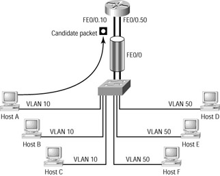
Figure 7.4: Candidate packet
Cache Entry Exists
When frames destined for an MLS-RP MAC address enter the switch, the switch checks whether a cache entry has been made that matches the attributes of the current packet.
As was previously mentioned briefly, each frame has distinguishing characteristics or attributes that enable the MLS-SE to categorize a packet into a flow. For instance, all packets from a particular IP address and destined for a different IP address can be placed by a switch into a flow. A flow entry can use IP addresses as well as, optionally, layer 4 information. The MLS-SE uses these cache attributes to match header information in future incoming packets. If an incoming packet has the same attributes as an established flow cache entry, the packet is layer 3– or shortcut-switched.
No Cache Entry
When an incoming frame destined for the MLS-RP is compared against the cache and no existing flow entry is found, a new cache entry is made. At this point, the packet is tagged as a candidate packet.
After the cache entry is made, the packet is forwarded to the router (MLS-RP) for normal processing. Here the router performs the route lookup, rewrites the layer 2 header, and sends the packet out the next-hop interface, whichever it might be.
The state of the MLS cache is only partial at this stage. A complete flow cache has not been established because the MLS-SE has only seen a packet come in and be forwarded to the router. It still needs to see the packet come back from the router before the flow is complete.
Identifying Enable Packets
Enable packets are the missing piece of the flow cache puzzle. Just as the MLS switch watches all incoming frames destined for the MLS router’s MAC addresses, it also watches all the packets coming from the MLS router.
It watches these packets, hoping for a match with the candidate packet cache entry. If it can make the match, the packet is tagged as an enable packet and the remaining elements of the flow cache are completed in the CAM table. Figure 7.5 depicts the occurrence of an enable packet.
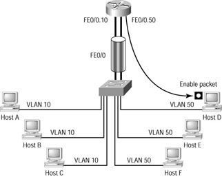
Figure 7.5: Enable packet
The match is made by using the following criteria:
-
The source MAC address is from an MLS-RP.
-
The destination IP matches the destination IP of a candidate packet.
-
The source MAC address is associated with the same XTAG value as the candidate packet’s destination MAC address.
If all three of these criteria are met, the MLS-SE completes the shortcut cache entry.
Frame Modification
It is important to understand that this shortcut switching occurs at layer 3. The layer 2 frames that are a part of the conversation but come after the first frame are rewritten by the switch. Normally, a router (layer 3 device) would rewrite the frame with the necessary information. A rewrite consists of changing the VLAN assignment, the source and destination MAC addresses, and the checksums. The MLS-SE can also modify the TTL, TOS, and encapsulation.
Because these packets are no longer sent to the router, the MLS-SE must perform the rewrite function. When the switch changes the source and destination MAC addresses, the MLS-SE uses the MAC address of the MLS-RP for the source, and it changes the destination MAC to the MAC of the directly connected host. Through this procedure, the frame appears to the destination host as if it had come through the router. Figure 7.6 depicts the differences between the incoming frame and the exiting frame.
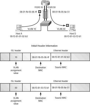
Figure 7.6: Frame modification
Subsequent Packets
After the candidate and enable packets have been identified and a shortcut, or flow cache, has been established, subsequent packets are forwarded by the switch to the destination without the use of the router. Because the MLS-SE has the capability to rewrite the frames, it can make the necessary modifications and forward the frame directly to the destination host.
The MLS-SE caches the necessary information, such as the source and destination IP addresses, the source and destination MAC addresses, and the MLS-RP-related MAC addresses. Using this information, the MLS-SE is then capable of identifying packets belonging to a specific flow, rewriting the frame, and forwarding the packets to the proper destination.
Disabling MLS
There is a right way and a wrong way to disable MLS on a router or switch. Both methods are discussed here.
The Right Way
The correct way to disable MLS depends on the equipment that you are using. Disabling MLS on a router can be paralleled with disabling MLS on an MSFC for a 6500 series switch. The command is even the same: no mls rp ip issued from the interface on either the router or the MSFC. To disable it completely, you can issue the same command from global configuration mode. The consequences of this action vary depending on the system on which it is issued. When the command is issued on the router, the router alone disables MLS. When it’s issued on an MSFC, MLS is disabled on the MSFC and the switch itself.
MLS is enabled by default for IP traffic and disabled for IPX. To disable MLS on a 6000 series, MLS should be disabled by issuing the no ip mls command on the MSFC.
The Wrong Way
There are several ways to inadvertently disable MLS on switches. Some are temporary, and others are permanent. Here is a list of MSFC/router commands that can disable MLS:
-
no ip routing
-
ip security
-
ip tcp compression-connections
-
ip tcp header-compression
-
clear ip route
By disabling IP routing on the MSFC or router, you automatically disable MLS. The ip security command disables MLS on the interface to which the command is applied. The same results occur with the ip tcp compression commands. Finally, the clear ip route command simply clears the MLS cache entries, and the flow caches must be reestablished.
EAN: 2147483647
Pages: 174