1.7 An Introduction to the Intel 80x86 CPU Family
|
1.7 An Introduction to the Intel 80x86 CPU Family
Thus far, you've seen a couple of HLA programs that will actually compile and run. However, all the statements appearing in programs to this point have been either data declarations or calls to HLA Standard Library routines. There hasn't been any real assembly language. Before we can progress any further and learn some real assembly language, a detour is necessary; for unless you understand the basic structure of the Intel 80x86 CPU family, the machine instructions will make little sense.
The Intel CPU family is generally classified as a Von Neumann Architecture Machine. Von Neumann computer systems contain three main building blocks: the central processing unit (CPU), memory, and input/output devices (I/O). These three components are connected together using the system bus (consisting of the address, data, and control busses). The block diagram in Figure 1-4 shows this relationship.
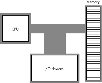
Figure 1-4: Von Neumann Computer System Block Diagram.
The CPU communicates with memory and I/O devices by placing a numeric value on the address bus to select one of the memory locations or I/O device port locations, each of which has a unique binary numeric address. Then the CPU, I/O, and memory device pass data between themselves by placing the data on the data bus. The control bus contains signals that determine the direction of the data transfer (to/from memory, and to/from an I/O device).
Within the CPU the registers is the most prominent feature. The 80x86 CPU registers can be broken down into four categories: general purpose registers, special-purpose application accessible registers, segment registers, and specialpurpose kernel mode registers. This text will not consider the last two sets of registers. The segment registers are not used much in modern 32-bit operating systems (e.g., Windows, BeOS, and Linux); because this text is geared around programs written for 32-bit operating systems, there is little need to discuss the segment registers. The special-purpose kernel mode registers are intended for writing operating systems, debuggers, and other system level tools. Such software construction is well beyond the scope of this text, so once again there is little need to discuss the special purpose kernel mode registers.
The 80x86 (Intel family) CPUs provide several general purpose registers for application use. These include eight 32-bit registers that have the following:
EAX, EBX, ECX, EDX, ESI, EDI, EBP, and ESP
The "E" prefix on each name stands for extended. This prefix differentiates the 32-bit registers from the eight 16-bit registers that have the following names:
AX, BX, CX, DX, SI, DI, BP, and SP
Finally, the 80x86 CPUs provide eight 8-bit registers that have the following names:
AL, AH, BL, BH, CL, CH, DL, and DH
Unfortunately, these are not all separate registers. That is, the 80x86 does not provide 24 independent registers. Instead, the 80x86 overlays the 32-bit registers with the 16-bit registers, and it overlays the 16-bit registers with the 8-bit registers. Figure 1-5 on the next page shows this relationship.
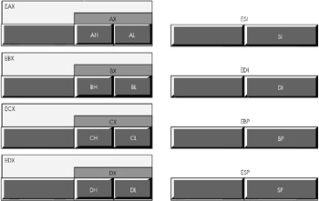
Figure 1-5: 80x86 (Intel CPU) General Purpose Registers.
The most important thing to note about the general purpose registers is that they are not independent. Modifying one register may modify as many as three other registers. For example, modification of the EAX register may very well modify the AL, AH, and AX registers. This fact cannot be overemphasized here. A very common mistake in programs written by beginning assembly language programmers is register value corruption because the programmer did not fully understand the ramifications of Figure 1-5.
The EFLAGS register is a 32-bit register that encapsulates several single-bit boolean (true/false) values. Most of the bits in the EFLAGS register are either reserved for kernel mode (operating system) functions or are of little interest to the application programmer. Eight of these bits (or flags) are of interest to application programmers writing assembly language programs. These are the overflow, direction, interrupt disable[4], sign, zero, auxiliary carry, parity, and carry flags. Figure 1-6 shows the layout of the flags within the lower 16 bits of the EFLAGS register.
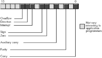
Figure 1-6: Layout of the Flags Register (Lower 16 Bits of EFLAGS).
Of the eight flags that are usable by application programmers, four flags in particular are extremely valuable: the overflow, carry, sign, and zero flags. Collectively, we will call these four flags the condition codes.[5] The state of these flags lets you test the result of previous computations. For example, after comparing two values, the condition code flags will tell you if one value is less than, equal to, or greater than a second value.
One important fact that comes as a surprise to those just learning assembly language is that almost all calculations on the 80x86 CPU involve a register. For example, to add two variables together, storing the sum into a third variable, you must load one of the variables into a register, add the second operand to the value in the register, and then store the register away in the destination variable. Registers are a middleman in nearly every calculation. Therefore, registers are very important in 80x86 assembly language programs.
Another thing you should be aware of is that although some registers are referred to as "general purpose" you should not infer that you can use any register for any purpose. The SP/ESP register pair for example, has a very special purpose that effectively prevents you from using it for any other purpose (it's the stack pointer). Likewise, the BP/EBP register has a special purpose that limits its usefulness as a general purpose register. All the 80x86 registers have their own special purposes that limit their use in certain contexts. For the time being, you should simply avoid the use of the ESP and EBP registers for generic calculations; also keep in mind that the remaining registers are not completely interchangeable in your programs.
1.7.1 The Memory Subsystem
A typical 80x86 processor running a modern 32-bit OS can access a maximum of 232 different memory locations, or just over four billion bytes. A few years ago, four gigabytes of memory would have seemed like infinity; modern machines, however, are pushing this limit. Nevertheless, because the 80x86 architecture supports a maximum four-gigabyte address space when using a 32-bit operating system like Windows or Linux, the following discussion will assume the fourgigabyte limit.
Of course, the first question you should ask is, "What exactly is a memory location?" The 80x86 supports byte addressable memory. Therefore, the basic memory unit is a byte, which is sufficient to hold a single character or a (very) small integer value (we'll talk more about that in the next chapter).
Think of memory as a linear array of bytes. The address of the first byte is zero, and the address of the last byte is 232-1. For a Pentium processor, the following pseudo-Pascal array declaration is a good approximation of memory:
Memory: array [0..4294967295] of byte;
C/C++ and Java users might prefer the following syntax:
byte Memory[4294967296];
To execute the equivalent of the Pascal statement "Memory [125] := 0;" the CPU places the value zero on the data bus, the address 125 on the address bus, and asserts the write line (this generally involves setting that line to zero), as shown in Figure 1-7.
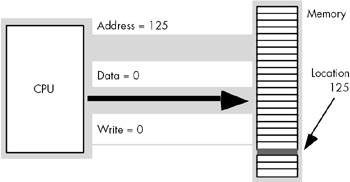
Figure 1-7: Memory Write Operation.
To execute the equivalent of "CPU := Memory [125];" the CPU places the address 125 on the address bus, asserts the read line (because the CPU is reading data from memory), and then reads the resulting data from the data bus (see Figure 1-8).
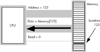
Figure 1-8: Memory Read Operation.
This discussion applies only when accessing a single byte in memory. So what happens when the processor accesses a word or a double word? Because memory consists of an array of bytes, how can we possibly deal with values larger than a single byte? Easy, to store larger values the 80x86 uses a sequence of consecutive memory locations. Figure 1-9 shows how the 80x86 stores bytes, words (two bytes), and double words (four bytes) in memory. The memory address of each of these objects is the address of the first byte of each object (i.e., the lowest address).
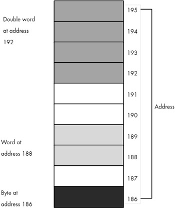
Figure 1-9: Byte, Word, and Double Word Storage in Memory.
Modern 80x86 processors don't actually connect directly to memory. Instead, there is a special memory buffer on the CPU known as the cache (pronounced "cash") that acts as a high-speed intermediary between the CPU and main memory. Although the cache handles the details automatically for you, one fact you should know is that accessing data objects in memory is sometimes more efficient if the address of the object is an even multiple of the object's size. Therefore, it's a good idea to align four-byte objects (double words) on addresses that are an even multiple of four. Likewise, it's most efficient to align two-byte objects on even addresses. You can efficiently access single-byte objects at any address. You'll see how to set the alignment of memory objects in a later chapter.
Before leaving this discussion of memory objects, it's important to understand the correspondence between memory and HLA variables. One of the nice things about using an assembler/compiler like HLA is that you don't have to worry about numeric memory addresses. All you need to do is declare a variable in HLA and HLA takes care of associating that variable with some unique set of memory addresses. For example, if you have the following declaration section:
static i8 :int8; i16 :int16; i32 :int32;
HLA will find some unused eight-bit byte in memory and associate it with the i8 variable; it will find a pair of consecutive unused bytes and associate i16 with them; finally, HLA will find four consecutive unused bytes and associate the value of i32 with those four bytes (32 bits). You'll always refer to these variables by their names, you generally don't have to concern yourself with their numeric address. Still, you should be aware that HLA is doing this for you behind your back.
[4]Applications programs cannot modify the interrupt flag, but we'll look at this flag later in this text, hence the discussion of this flag here.
[5]Technically the parity flag is also a condition code, but we will not use that flag in this text.
|
EAN: 2147483647
Pages: 246