| Many of the tools used in FreeHand are similar to tools found in other Studio MX programs. For instance, there is little variation in how the selection and drawing tools work between the programs. There are, however, a few "administrative" tools specific to FreeHand, as well as some fun creative tools discussed in the following sections. Page Tool The Page tool is used to visually change the size of a page to create custom dimensions. Select the Page tool and click on the page you want to change. A set of handles appears around the page edges (Figure 29.15). Simply drag one of the arrows to change the page size. Note that although the page size changes, the size of your artwork does not. Figure 29.15. Use the Page tool to visually change the size of a document page. 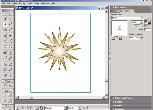
If you work with a lot of custom page sizes, you can save those dimensions on your list of standard page sizes. To add a custom page size to your list, follow these steps: - Select Edit from the bottom of the preset page size list in the Document panel.
- The Edit Page Sizes dialog box appears. Click the New button to create a new page size.
- Enter a name for your new page size.
- Enter the new page dimensions. The horizontal size goes in the x field; the vertical size goes in the y field.
- Click the Close button to close the dialog box.
- Your new custom size now appears with the list of preset page sizes.
You can also use the Page tool to swap the horizontal and vertical orientation of your pages. Simply select the Page tool and click on the page you want to change. A set of handles appears on the edges of the page. Place your cursor on the outside of a handle so that a curved arrow will appear. Click and drag the handle to rotate the page. Note that the page can only be rotated in 90% increments : from portrait to landscape or from landscape to portrait. The Page tool also allows you to duplicate pages. Select the Page tool and hold the Alt/Opt key as you drag the tool to duplicate a page (Figure 29.16). Release the mouse button when the new page appears. Figure 29.16. The Page tool can also be used to duplicate pages. 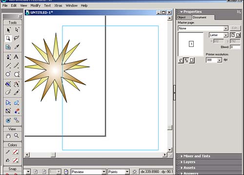
The Page tool is also used to move and organize your pages when you are working with multiple pages. Using the Page tool, select a page and drag it to its new location. You can use this feature to change the order of your pages or their location in relation to each other. Output Area Tool The Output Area tool is used to define a single area of your document for export. To use this tool, simply select it from the toolbar and click and drag to define the area for export (see Figure 29.17). After you've defined the export area, you can resize or delete it. A nice feature in FreeHand is that the export area is saved as part of the document attributes when you save the document. Figure 29.17. The Output Area tool is used to define an area for export. 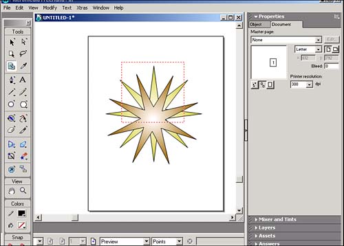
Variable Stroke Pen Tool Located in the Pencil tool group , the Variable Stroke Pen tool allows you to draw lines that are both straight and curvy. This tool is designed to replicate a natural brush stroke (Figure 29.18). If you are using a pressure-sensitive tablet, any changes in the pressure you apply changes the thickness of the stroke. The more pressure you apply, the thicker the stroke. The less pressure you apply, the thinner the stroke. If you do not have a pressure-sensitive tablet, you can simulate pressure by using the left (decrease pressure) and right (increase pressure) arrow keys. Figure 29.18. The Variable Stroke Pen tool replicates a natural brush stroke with the aid of a pressure-sensitive tablet or the left and right arrow keys. 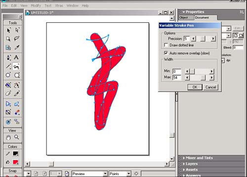
To set properties for your brush strokes, double-click the Variable Stroke Pen tool icon in the toolbar to open the Variable Stroke Pen dialog box. The Precision setting allows you to control how closely the tool follows the path you draw. Setting a low value smoothes out any minor variables as you draw. Setting a high value has your stroke follow any minor variables as you draw. If you check the box for the Draw Dotted Line option, a dotted line appears if you draw too quickly. The dotted line is replaced by your variable stroke line after you have finished drawing the line. If your computer is having a hard time keeping up with you as you whip through lines, you should consider using this option. The Auto Remove Overlap option eliminates any parts of the path that overlap (Figure 29.19). Figure 29.19. The figure on the right was drawn with the Auto Remove Overlap option selected. 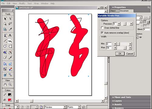
You can also define the minimum and maximum width for your stroke from 1 to 72 points. Calligraphic Pen Tool Located in the Pencil tool group, the Calligraphic Pen tool is used to create lines that resemble calligraphic strokes (Figure 29.20). This tool is also pressure sensitive. Using a pressure-sensitive tablet, or the left and right arrow keys, you can alter the thickness of the stroke. Increasing the pressure (or using the right arrow key) increases the stroke's thickness. Decreasing the pressure (or using the left arrow key) decreases the stroke's thickness. Figure 29.20. Use the Calligraphic Pen tool to create calligraphic strokes. 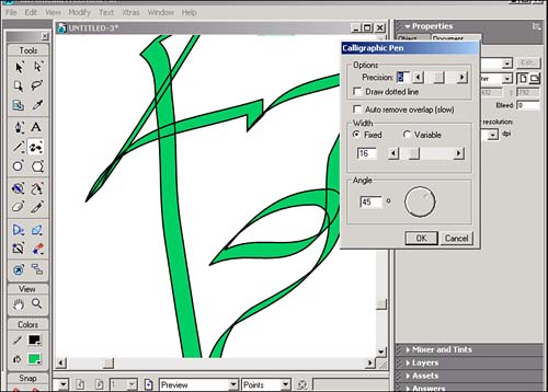
Double-click the Calligraphic Pen tool to open the Calligraphic dialog box. The Precision setting enables you to control how closely the tool will follow the path you draw. Setting a low value smoothes out any minor variables as you draw. Setting a high value has your stroke follow any minor variables as you draw. If you check the box for the Draw Dotted Line option, a dotted line appears if you draw too quickly. The dotted line is replaced by your variable stroke line after you have finished drawing the line. The Auto remove overlap option eliminates any parts of the path that overlap. You can also define the minimum and maximum width for your stroke from 1 to 72 points. Enter a value in the Angle field, or use the wheel, to set the angle for your stroke. Spiral As someone who has always been a Bezier-impaired individual, I feel that FreeHand's Spiral tool is the best invention since peanut butter and sliced bread. Located in the Line tool group, the Spiral tool gives you several options for creating spirals . Double-click the Spiral tool to open the Spiral dialog box (Figure 29.21). You can select between a non-expanding spiral and an expanding type. The non-expanding spiral has lines that are evenly spaced . The expanding type increases the distance between lines as the spiral moves out from its center. If you select an expanding spiral, use the slider or enter a number in the Expansion field to change your spiral's properties. The higher the number, the greater the expansion rate. Figure 29.21. Use the Spiral dialog box to control the attributes for your spiral. 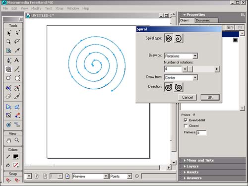
The Draw By List option lets you draw your spiral by specifying the number of rotations or the number of increments (the amount of space between lines in the non-expanding spiral or the starting radius in expanding spirals). The Draw From List option enables you to draw your spiral starting from the Center, Edge, or Corner. You can also change the direction of your spiral by selecting the Clockwise or Counterclockwise buttons . Arc Another drawing tool that prevents hair pulling is the Arc tool. As the name suggests, the Arc tool enables you to create a variety of arcs. Located in the Line tool group, double-click the Arc tool to open the Arc dialog box (see Figure 29.22). Here you will find three settings for your arcs: -
Create Open Arc lets you create a simple arc. -
Create Flipped Arc enables you to reflect the arc from one direction to another. -
Create Concave Arc lets you create a you guessed it a concave arc. Figure 29.22. The Arc dialog box lets you select three types of arcs to create. 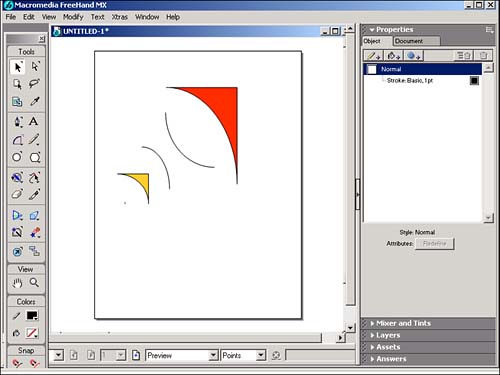
After you start drawing your arc, you can use the Cmd/Ctrl key to close or open the arc. Hold the Shift key to constrain your arc to quarter circles. Use the Opt/Alt key when you're drawing to flip the arc vertically or horizontally. Scale The Scale tool allows you to resize an object. Select an object (or group of objects) and click anywhere on the current document to determine a scale center point, then drag to scale the selected object (Figure 29.23). Figure 29.23. Use the Scale tool to visually resize a selected object. 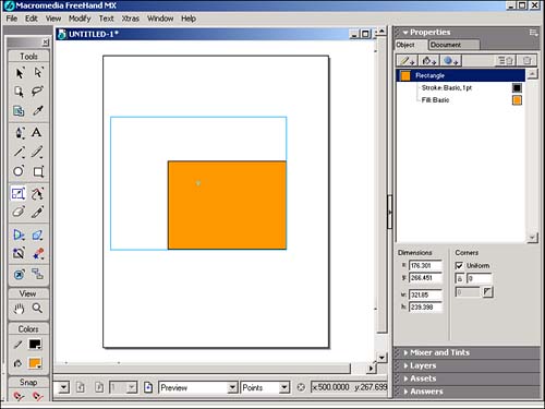
Hold the Shift key as you drag to scale an object proportionally. To copy the object as you scale it, hold the Opt/Alt key. The trick here is to release the mouse button first, then the Opt/Alt key, to create the copy. You can also scale an object by using the Transform Panel (Figure 29.24). Double-click the Scale tool to view the Transform Panel. In the Transform Panel, you can -
Enter a percentage value that you want to change your object. -
Uncheck Uniform to adjust X and Y scaling independently. -
Adjust the horizontal scale by changing the X value. -
Adjust the vertical scale by changing the Y value. -
Change the point of transformation from the center of the object by entering coordinates in the x and y fields. -
Check Contents to include any items pasted inside the object. -
Check Fills to scale any fills. -
Check Strokes to scale the size of the stroke as the object is scaled. -
Enter the number of copies created of the scaled object. Figure 29.24. Another way to numerically resize a selected object is to use the Transform Panel. 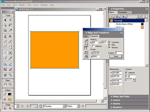
Rotate The Rotate tool enables you to change the orientation of an object. Select an object (or group of objects) and click anywhere on the current document to determine a rotation center point, then drag to rotate the object (Figure 29.25). Hold the Shift key to constrain the rotation to 45 ° increments. Figure 29.25. Use the Rotation tool to visually rotate an object. 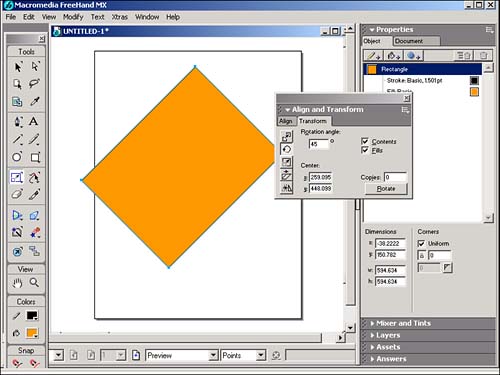
The farther you drag your cursor away from the rotation point, the easier it will be to finesse the rotation. You can also double-click the Rotate tool to view the Transformation palette (Figure 29.26), where you can -
Set the number of degrees for the rotation. -
Change the point of transformation from the center of the object by entering coordinates in the x and y fields. -
Check Contents to rotate any items pasted inside the object. -
Check Fills to rotate any fills inside the object. Figure 29.26. Use the Transformation palette to numerically set the degrees of rotation. 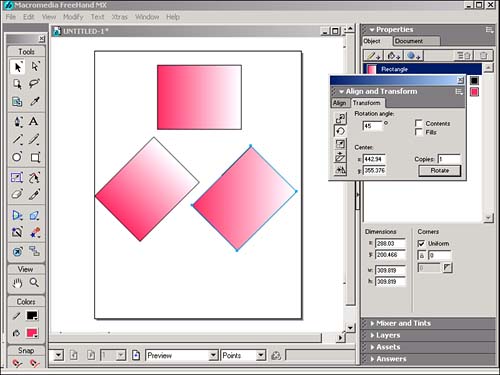
Reflect The Reflect tool enables you to create a mirror image of an object. Select an object (or group of objects) and click anywhere on the current document to determine a reflection center point, then drag to reflect the object (Figure 29.27). Hold the Shift key to constrain the rotation to 45 ° increments. Hold the Opt/Alt key to create a copy. Figure 29.27. The Reflect tool is used to simplify the process of creating a mirror image of an object. 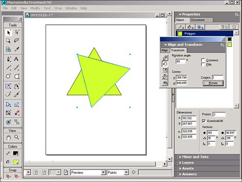
You can also double-click the Reflect tool to view the Transformation palette, where you can -
Enter the angle amount that you want to reflect around by using the Reflect Axis field. -
Change the point of transformation from the center of the object by entering coordinates in the x and y fields. -
Check Contents to reflect any items pasted inside the object. -
Check Fills to reflect any fills inside the object. -
Enter the number of copies created of the reflected object. Skew The Skew tool enables you to distort an object along an axis. Select an object (or group of objects) and click anywhere on the current document to determine a skew center point, then drag to skew the object (Figure 29.28). Hold the Shift key to constrain the skew to either the horizontal or vertical axis, depending on which way you drag your cursor. Hold the Opt/Alt key to create a copy. Figure 29.28. Use the Skew tool to distort an object to create the illusion of a third dimension. 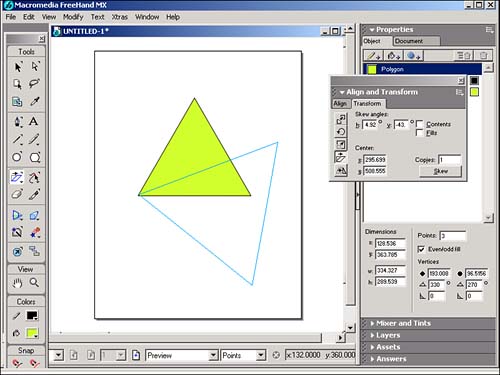
You can also double-click the Skew tool to view the Transformation palette, where you can -
Enter the horizontal and vertical angle amount that you want to skew. -
Change the point of transformation from the center of the object by entering coordinates in the x and y fields. -
Check Contents to skew any items pasted inside the object. -
Check Skew to reflect any fills inside the object. -
Enter the number of copies created of the skewed object. Freeform The Freeform tool is another gift for us Bezier-impaired individuals. Rather than adjusting points or handles, you can use the Freeform tool to basically knead your object like a piece of dough (Figure 29.29). Figure 29.29. The object on the right used to look like the object on the left until the Freeform tool was put into play. 
Double-click the Freeform tool to open the Freeform Tool dialog box (Figure 29.30). There are two modes you can use: Push/Pull and Reshape Area. Figure 29.30. Control how the Freeform tool manipulates an object with the Freeform Tool dialog box. 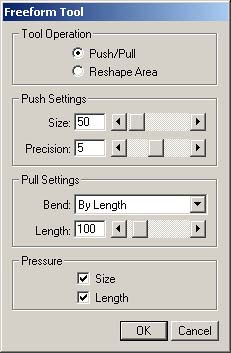
Select Push/Pull to change the shape of the object, but only the portion that you select. The Freeform Tool dialog box presents you with the following options: -
Set the Size field (use the slider or enter a value between 1 “1,000) to control the size of the area you are pushing. -
Set the Precision field (1 “10) to control the sensitivity of the tool; the greater the value, the higher the sensitivity. -
Select one of two Pull settings: Bend By Length pulls will pull anywhere along a path; Bend Between Points will pull only between anchor points. -
Set the Length field to control how much the path will be altered . -
If you have a pressure-sensitive tablet, you can check the Size or Length boxes to control how pressure on the tablet affects the tool (Figure 29.31). You can also use the left arrow key to simulate a decrease in pressure and the right arrow key to simulate an increase in pressure. Figure 29.31. The object on the right was "cut" while holding down the left arrow key to simulate a decrease in pressure. 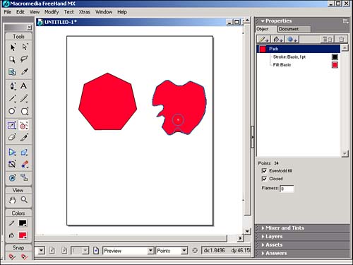
Select Reshape Area to change the shape of the object. This produces a result similar to that of the Push/Pull tool, except that the effect weakens as you drag the pointer. The Freeform Tool dialog box presents you with the following options: -
Set the Size field (use the slider or enter a value between 1 “1,000) to control the size of the Reshape Area. -
Set the Strength field (1 “50)to control how long the tool will work while you drag it. -
Set the Precision field (1 “10) to control the sensitivity of the tool; the greater the value, the higher the sensitivity. -
If you have a pressure-sensitive tablet, you can check the Size or Length boxes to control how pressure on the tablet affects the tool. You can also use the left arrow key to simulate a decrease in pressure and the right arrow key to simulate an increase in pressure. Roughen In spite of the name, the Roughen tool does not allow you to intimidate objects on your document. The Roughen tool lets you make smooth paths jagged and irregular (Figure 29.32). Figure 29.32. The original object on the top and same object on the bottom after it has gone a few rounds with the Roughen tool. 
Double-click the Roughen tool to view the Roughen dialog box. Adjust the Amount field to control the number of segments per inch (1 “100) that are added when you use the tool. Select a Rough edge to add corner points. Select Smooth edge to add curved points. The farther you drag the tool, the greater the distortion. Bend The Bend tool enables you to warp, in or out, an object's path segments (Figure 29.33). The point where you start to drag becomes the center of the bend and the longer you drag, the more bend you create. Figure 29.33. Use the Bend tool to distort an object as if you were pulling it like taffy. 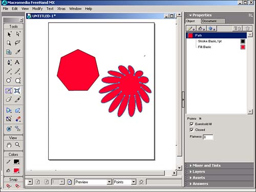 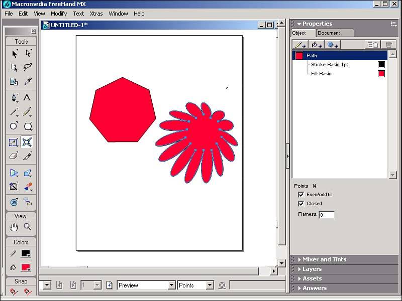
Double-click the Bend tool to open the Bend dialog box. Enter a value or adjust the slider (1 “10) to select the number of points per inch that are added. Eraser Because FreeHand operates in a vector world, the Eraser tool cannot be used to remove pixels like in Fireworks. The Eraser tool operates by reshaping paths, rather than removing them (Figure 29.34). Figure 29.34. Note that the Eraser tool only reshapes paths as seen in the points created by the "erased" section on the left side of the object. 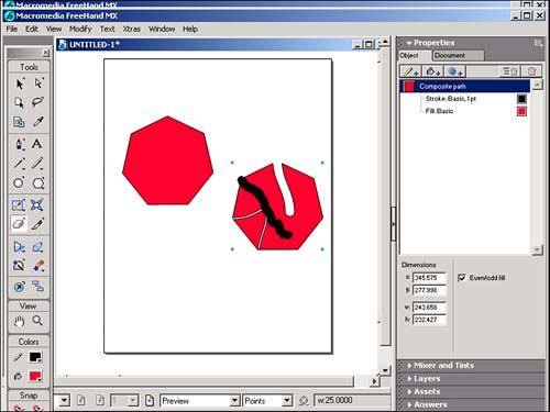
Double-click the Eraser tool to view the Eraser Tool dialog box. Use the Min. and Max. fields to set the width of your eraser (1 “72 points) if you are using a pressure-sensitive tablet. If you are not using a pressure-sensitive tablet, use the Min. value to change the size of your eraser. Hold the Opt/Alt key as you drag to erase in a straight line. Hold the Opt/Alt + Shift keys to constrain the eraser in 0 °, 45 °, and 90 ° increments. Knife Tool Use this tool to cut single objects into two or more objects. Select an object (or group of objects) and select the Knife Tool. Click and drag across the object to slice through it. After an object is sliced, deselect it to move portions separately. Double-click the Knife tool to view the Knife Tool dialog box. Select the Freehand option to create curved or more natural cuts or the Straight option to create only straight-line cuts (Figure 29.35). Figure 29.35. Using the knife tool to make (clockwise, starting with the top left object) freehand cuts, straight-line cuts, and freehand cuts with varying widths. 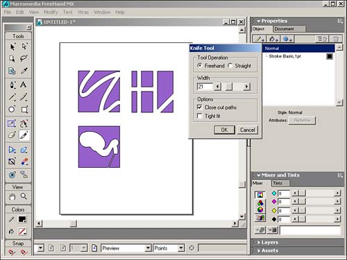
Set the Width (0 “72 points) to control the space between cuts. Select Close Cut Paths so that objects cut by the Knife tool are closed when you're finished cutting. Think of it as a self-healing wound. Select Tight Fit if you want the Knife tool to precisely follow your mouse movement. Use the Opt/Alt key as you drag to temporarily make straight line cuts. Use the Shift key to constrain your cuts to 45 ° angles. Perspective Tool The Perspective tool is used to adjust the Perspective Grid (View, Perspective Grid, Show as seen in Figure 29.36)and to attach objects to the Perspective Grid. If you're not careful, you could be up to the wee hours of the morning just playing with the Perspective tool. It's addicting. Figure 29.36. Use the Show command in the View menu to see the Perspective Grid. 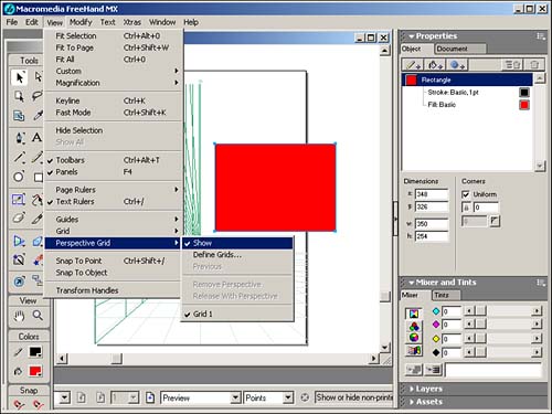
To attach an object to the Perspective Grid, use the Perspective tool to drag the object to a section of the grid. Before letting go of the mouse button, use one of the arrow keys to determine where the object is to be attached: -
Left arrow attaches the object to left grid. -
Right arrow attaches the object to the right grid. -
Down arrow attaches the object to the bottom grid, but lined up with the right vanishing point. -
Up arrow attaches the object to the bottom grid, but lined up with the left vanishing point. The Perspective tool is also used to move objects along the Perspective grid (Figure 29.37). Hold the Opt/Alt key to copy an object while dragging it on the grid. Hold the Shift key to keep the object's movement within the grid axis. Figure 29.37. Use the Perspective tool to move objects attached to the Perspective Grid. 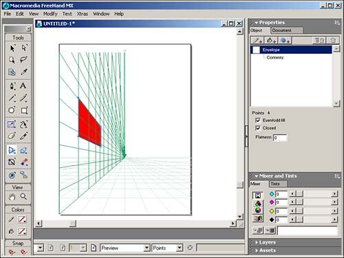
3D Rotation Tool The 3D Rotation tool enables you to apply a three-dimensional rotation to a two- dimensional object. To use the 3D Rotation tool, select the object you want to modify. Choose the 3D Rotation tool, then click and drag the cursor away from the object (Figure 29.38). The farther you drag the line away from the object, the greater the rotation. Figure 29.38. Use the 3D Rotation tool make a 2D object rotate in the third dimension. 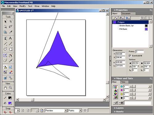
Double-click the 3D Rotation tool to view the 3D Rotation dialog box (Figure 29.39). Selecting Easy enables you to change the rotation and distance. The Rotate From Menu option enables you to choose where the rotation point will occur: -
A mouse click sets the pivot point to the position where you click. -
Center of Selection sets the pivot point to the center of the object. -
Center of Gravity sets the pivot point to the center of an uneven -shaped object. -
Origin sets the pivot point to the bottom-left corner of the object's bounding box. Figure 29.39. Change rotation settings in the 3D Rotation dialog box. 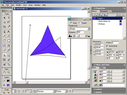
Selecting the Expert button displays more controls (see Figure 29.40). The Project From Menu option enables you to set the projection point, or vanishing point: -
A mouse click sets the projection point to the position where you click. -
Center of Selection sets the projection point to the center of the object. -
Center of gravity sets the projection point to the center of an uneven-shaped object. -
Origin sets the pivot point to the bottom-left corner of the object's bounding box. -
X/Y coordinates set the projection points from the coordinates you input. Figure 29.40. Check the Expert button in the dialog box to view more controls for the 3D Rotation tool. 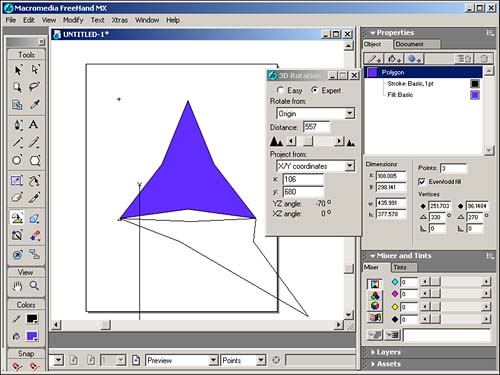
Fisheye Lens Tool The Fisheye Lens tool enables you to create a concave or convex lens effect for your object (Figure 29.41). Select the object you want to modify. If you want to modify text, make sure you have converted the text to paths (Text, Convert to Paths) first. Select the Fisheye Lens tool and drag the cursor to create an oval over the area you want to distort. Use the Opt/Alt key to create a distortion from the center outward. Use the Shift key to constrain the distortion to a circular shape. Release the mouse button to apply the effect. Figure 29.41. Use the Fisheye Lens tool to distort objects as if they were viewed through a camera's fisheye lens. 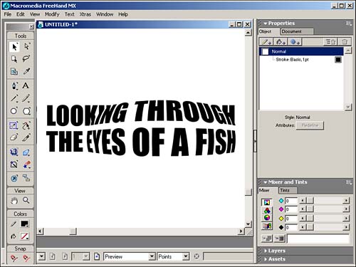
Double-click the Fisheye Lens tool to open the Fisheye Lens dialog box (Figure 29.42). Enter a value in the Perspective field or use the slider to alter the perspective from Convex (positive numbers) to Concave (negative numbers ). Figure 29.42. The Fisheye Lens dialog contains the settings to control the distortion effect. 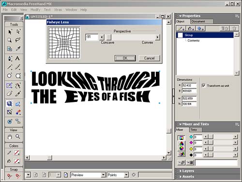
Extrude Tool Another extremely addictive tool is the Extrude tool. This sophisticated tool lets you take a 2-D object and project it into a 3-D object. There are several actions you can do with this tool to extrude an object. To extrude an object, use the Extrude tool to drag in the direction of the extrusion (Figure 29.43). As long as you keep the mouse button depressed, you can increase the depth and angle of the extrusion . Figure 29.43. Use the Extrude tool to project objects into the realm of 3D. 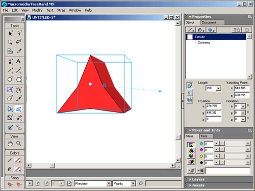
To change the extruded object's orientation, double-click the object with the Extrude tool to enable the orientation controls (Figure 29.44). Drag inside the orientation circle to change the horizontal or vertical orientation; drag outside the orientation circle to change the depth. Figure 29.44. Using the orientation controls, you can rotate the extruded object along three axes (x, y, and z). 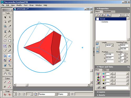
Use the Object panel to control the extrusion numerically. Select the Extrude icon to display the numerical equivalents of the modification fields that you can set by eye with the Extrude tool (Figure 29.45). Figure 29.45. You can also rotate an extruded object by entering values in the Object panel. 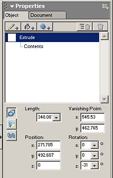
The Object panel also lets you control the following Surface options by selecting the Surface button: -
Select Flat to apply the surface color with no lighting effects. -
Select Shaded to apply a shaded lighting effect. -
Select Wireframe to display a transparent wireframe of the object. -
Select Mesh to display polygons as the transparent structure of the object. -
Select Hidden Mesh to show the exterior polygons as well as the fill for the object. Set the number of Steps to increase (higher value) or decrease (lower value) the smoothness of the shading. Use the Ambient control to increase or decrease the amount of light on the extruded object. Use the Light 1 and Light 2 settings to control the direction and intensity of lighting sources for your object. With all these controls, you can see how addictive it can be to create extrusions. FreeHand has given us a very powerful tool where apparently the only limits are your imagination . Smudge Tool The Smudge tool enables you to add a soft edge to an object. Select the object that you want to modify and then select the Smudge tool. Your cursor changes into the Smudge fingers. Drag the fingers in the direction you want the smudge to go. Release the mouse button to create the smudge. Hold the Opt/Alt key to create a smudge from the center outward. Double-click the Smudge tool to open the Smudge dialog box (Figure 29.46). Drag colors from the Swatches panel or the Color Mixer into the Fill and Stroke boxes to change the smudge colors. Figure 29.46. Use the Smudge tool to smudge the edges of an object to create the appearance of a drop shadow. 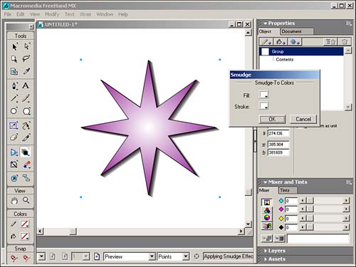
The number of steps in your smudge is determined by the printer resolution in the Document Inspector. To create a smoother smudge effect, increase the printer resolution. Shadow Tool Very similar to the Smudge tool, the Shadow tool lets you create sophisticated shadows. Select the object you want to modify. Double-click the Shadow tool to open the Shadow dialog box (Figure 29.47). From the Type menu: -
Select Hard Edge to apply a single object as a shadow. -
Select Soft Edge to apply a blend shadow. -
Select Zoom to apply a blend that is placed to create a 3D effect. Figure 29.47. The Shadow tool dialog box enables you to control how the shadow is applied to the object. 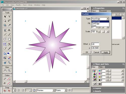
From the Fill menu (Figure 29.48), -
Select Color to choose a specific color for the shadow. -
Select Shade to create a shadow color that is darker than the original object. -
Select Tint to create a shadow color that is lighter than the original object. -
Use the slider to adjust the lightness or darkness of the shadow. Figure 29.48. The Fill menu lets you control the attributes of the shadow's fill color. 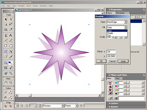
Set the x and y Offset amounts to determine the shadow's position. Trace Tool If you've ever had to re-create someone's logo from a business card or a facsimile copy of letterhead, then you're going to love FreeHand's Trace tool. After you've scanned the artwork and imported (File, Import) it into your document, you can use the Trace tool to recognize the shapes in the artwork and convert them into vector paths. Before you start tracing, you need to double-click the Trace tool to open the Trace tool dialog box so you can get your settings squared away (Figure 29.49). The dialog box lets you set the following properties: -
Color Mode ” Select the number of colors or shades of grays (2-256) and between Colors or Gray for the final tracing. If you selected colors, you then have the option of selecting RGB or CMYK color models. -
Resolution ” Select High resolution to capture the most details, Normal to capture fewer details, and Low to capture the fewest details. -
Trace layers ” Select All to use all the document layers, Foreground to use only the foreground layers, and Background to use only the background layers. -
Path conversion ” Select Outline to trace the outside border of the artwork, Centerline to trace the center of the artwork, Centerline/Outline to use both options, and Outer Edge to trace only the outside edge of the artwork. -
Path overlap ” Select None to trace line art and text, Loose to trace continuous-tone images, or Tight for more precise color tracing. -
Trace Conformity ” Set a value to determine how closely the traced path will follow the original artwork. Values can range from 0 (less conformity with fewer points) to 10 (greater conformity with more points). -
Noise Tolerance ” Set a value to eliminate noise, or stray pixels, in a low-quality original (like the facsimile letterhead logo!). Values can range from 0 (more noise retained) to 20 (more noise eliminated). -
Wand Color Tolerance ” Adjust the slider to control the sensitivity when selecting areas of contiguous colors. Values can range from 0 (narrower range of colors selected) to 255 (wider range of colors selected). Figure 29.49. The Trace tool dialog box offers several ways to control the accuracy of your tracing. 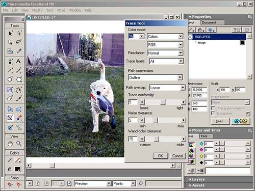
After you've selected your settings, use the Trace tool to drag a selection marquee around the portion of the image to be traced. FreeHand traces it automatically. Blend Tool The Blend tool lets you create a transition between two or more paths (Figure 29.50). You can create a blend between two or more identical shapes where only the color changes or two or more different shapes to make one object change its shape and/or color to another object; you can also create a blend to distribute objects by blending one object to a copy of itself. Figure 29.50. The Blend tool is used to "morph" one object into another. 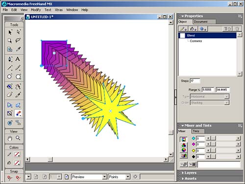
Select two or more objects that you want to blend. Choose the Blend tool and drag from one object to another. The intermediate steps between the two objects will be displayed. Release the mouse button to complete the blend. To add another object to the blend, use the Blend tool to drag from the blended objects to the new object, or vice versa. To change the number of steps in a blend, use the blend controls that appear in the Objects panel (Figure 29.51). Figure 29.51. The Object panel displays blend controls when the blended objects are selected. 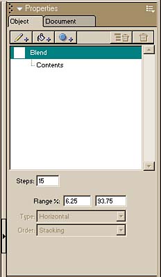
Note that you can also select and move any of the transitional shapes by using the Modify, Ungroup command to ungroup the shapes. Use the Subselect tool to select the transitional shape you want to move. Mirror Tool The Mirror tool lets you create multiple reflected and rotated objects (Figure 29.52). Double-click the Mirror tool to view the Mirror dialog box, where you can choose the axis upon which the reflection takes place: -
Vertical reflects the object from left to right. -
Horizontal reflects the object from top to bottom. -
Horizontal & Vertical reflects the object along both vertical and horizontal axes. -
Multiple reflects the object around multiple axes. By selecting Multiple, you can use the slider to control the number of axes around which the object will reflect, as well as select Rotate or Reflect. Figure 29.52. The Mirror tool is used to create a mirror image of a selected object. 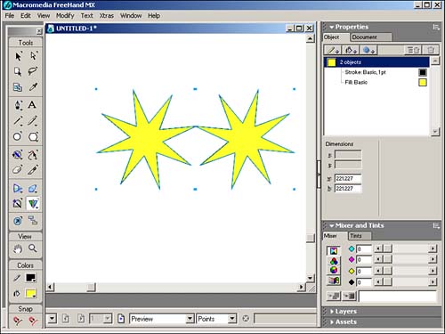
The preview area shows you how each setting will affect your object. Graphic Hose Tool Although oddly named in my opinion, the Graphic Hose tool is an interesting tool that lets you paint with stored objects. Stored objects are located in the Graphic Hose panel (Figure 29.53). Figure 29.53. The Graphic Hose tool enables you to paint nifty effects using stored objects. 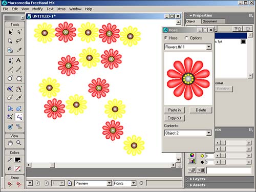
Before you start "hosing" the document, you'd better modify some settings so you know what graphics you'll be using. Double-click the Graphic Hose tool to open the Graphic Hose panel (Figure 29.54). Select the Options radio button to display the Options controls. Figure 29.54. Use the Graphic Hose panel to determine how stored objects are displayed on the page when you're painting with the Graphic Hose tool. 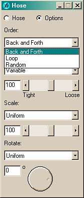
Control the order in which the objects are placed on the page with the Order menu: -
Loop applies the objects in numerical order. -
Back and Forth applies the objects in forward, then reverse order. -
Random applies the objects in no particular order. Control the distance between objects with the Spacing menu (Figure 29.55): -
Grid spaces the objects onto a grid as determined by the Grid field. -
Variable spaces the objects in either a Tight or Loose setting. -
Random spaces the objects as the Computer Gods dictate . Figure 29.55. The Spacing menu enables you to control the amount of space between objects used in the Graphic Hose tool. 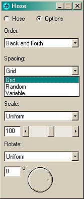
Control the size of the objects with the Scale menu (Figure 29.56): Figure 29.56. Choose between Uniform or Random size of the Graphic Hose objects. 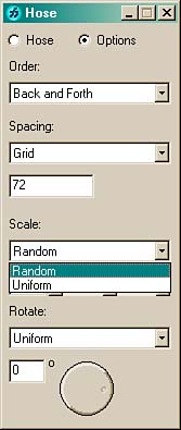
Control the rotation of the objects with the Rotate menu and angle wheel (see Figure 29.57): -
Uniform sets one angle for all objects. -
Incremental applies rotations in specific increments from one object to the next . -
Random rotates the objects with complete disregard for authority. Chaos could ensue so please use this setting with caution. Figure 29.57. Select one of three rotation controls to apply to the Graphic Hose objects. 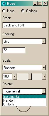
Although you can have some fun with the FreeHand-supplied Clovers, Flowers, Leaves, and Shapes, the real fun starts when you create your own Graphic Hose objects. Objects used in the Graphic Hose are stored in sets. For example, one set could include one blue circle, one red square, and yellow star. A set could also include just one object. Draw the objects you want to put in the set and then double-click the Graphic Hose tool to open the Graphic Hose panel. Click Hose to display the Hose sets. Choose New from the Sets menu to add a new set. A dialog box appears, giving you the opportunity to name your set (Figure 29.58). Figure 29.58. You can create custom Graphic Hose objects by copying and pasting objects into the Graphic Hose panel. 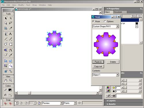
Copy the first object and click the Paste In button on the Graphic Hose panel. Continue to Copy and Paste In as necessary to complete your set. You are limited to 10 objects for each set. Chart Tool As the name implies, the Chart tool lets you create charts . To create a chart, select the Chart tool, click a starting point on the document and drag to set the initial size of the chart. The Chart dialog box automatically appears (Figure 29.59) and lets you start entering data in the cells . You can also Import data from other tab-delimited data sources. Figure 29.59. Use the Chart dialog box to enter data for your chart. 
Select the Chart Type button to select one of the following chart types (Figure 29.60): -
Grouped Column to compare data using bars. Each bar represents one cell of data. -
Stacked Column to compare the contribution of each value to a total across categories. Each bar represents a row of data. -
Line to show a trend over a period of time. Each line represents a column of data. -
Pie to display data in a circular graph with slices. Each cell of data represents a single slice. Each row of data produces a pie chart. -
Area to display filled areas representing the progress of data over time. This is a cousin to the Stacked Column. Each area represents a column of data in the worksheet. Each column's value is added to the previous column's total. -
Scatter to plot data as paired sets of coordinates to identify trends in data. Each coordinate represents a row of data containing two cells. Figure 29.60. The Chart Type window in the Chart dialog box lets you select from six types of charts. 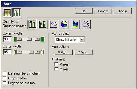
In FreeHand, each chart is treated as a series of grouped objects. Ungroup the chart (Modify, Ungroup) to edit individual chart elements such as stroke, fill, scale, and so on. Note that after you ungroup the chart, you can no longer go back and edit the data. You can apply Pictographs to replace the standard chart bars or lines with an image. Select and copy the FreeHand graphic you'd like to use, then use the Subselect tool to select a column in the chart. Select Xtras, Chart, Pictograph to view the Pictograph dialog box. Click Paste In to place your graphic in the preview window (Figure 29.61). Figure 29.61. Pictographs are used to replace standard chart elements with custom graphics. 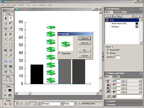
Check the Repeated check box to fill the columns with repeating copies of your graphic. Uncheck the Repeating check box to fill the column with one scaled object. Action Tool The Action tool enables you to apply actions to objects, such as creating links to other pages in the FreeHand document, printing a target page, and loading a target page as a movie (Figure 29.62). Figure 29.62. You can use the Action tool to create a page link. 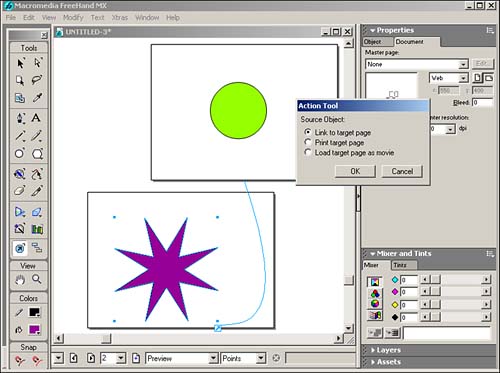
 For more on using the Action Tool, see Chapter 30, "Using FreeHand in Web Site Planning and Creation," page 852 . For more on using the Action Tool, see Chapter 30, "Using FreeHand in Web Site Planning and Creation," page 852 .
Connector Tool FreeHand's Connector tool is a fantastic aid for those burdened with creating graphical site maps or organizational charts (Figure 29.63). The Connector tool creates lines that stay connected to objects, no matter where you move them. You can also reshape and move your connector lines after they're drawn. Figure 29.63. The Connector tool creates dynamic lines that stay glued to objects no matter where you move them. 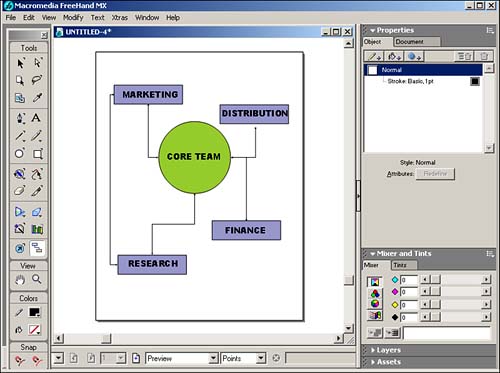
To use the Connector tool, you need to have at least two objects on your document. Select the Connector tool and position the cursor near the side, top, or bottom of the object where you want the connection to begin. Click and drag toward the side, top, or bottom of your second object that you want to connect. FreeHand automatically places arrowheads on the beginning and end of the connector line. You can modify these lines by using the Stroke Controls in the Objects Panel. After you have connected your objects, you can rearrange those objects and the connector lines will still stay attached. You can reshape the connector line by placing the cursor over the line. A plus sign and a double-headed arrow appear. Simply drag the cursor to reshape the connector line (see Figure 29.64). Figure 29.64. Connector lines can be reshaped even though they've been attached to an object. 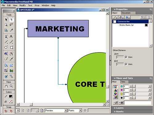
For more on using the Connector Tool, see Chapter 30, page 837 .
|