The Application Designer
The Application Designer
The application architect's primary task is to define the application's architecture, including its applications, services, and communication pathways. Using Visual Studio, the architect will define the metadata and configuration settings by using the Application Designer. Specifically, this means defining the following characteristics:
Types of applications (applications, services, or databases)
Communication pathways between applications (connections and endpoints)
Constraints and settings
The focus of the Application Designer is to assist in the development of SOA applications. This means that you are primarily modeling ASP.NET Web services and the applications that consume them.
NOTE
Many of the actual steps to create an application diagram are the same as those to create a logical datacenter diagram.
Creating Application Diagrams
Application diagrams can be created before any coding has started. This allows application architects, who may not be involved with the detailed implementation of a system, to use Visual Studio 2005 Team System to work on the design ahead of time. Designing these diagrams before application development gets underway allows the application architecture to be vetted against one or more logical datacenter diagrams, ensuring that it will successfully deploy. Issues caught early with the architecture are easier and less costly to fix than if coding has commenced. After a design has been validated the Application Designer will generate a skeleton implementation with projects, code, and configuration files that precisely match the design.
At a high level, here are the steps to create an application diagram:
Create a new Distributed System Solution project.
Select the Distributed System as a template.
Design your application by adding and configuring the appropriate application types, adding and configuring the appropriate endpoints, and connecting those endpoints.
TIP
One of the coolest features of Team System is the ability you have to simply add an application diagram to an existing solution and have it reverse engineer your code. This will generate the respective applications, endpoints, and connections on the diagram. Try it!
A solution can contain only one application diagram. It can, however, contain multiple logical datacenter diagrams, system diagrams, and deployment diagrams. This is because an application diagram is solution-scoped, as it can contain many applications that would be other projects under the solution. For example, you might want separate logical datacenter diagrams to represent separate eCommerce, B2B, and intranet hosting portions of a datacenter.
Here are the various types of application prototypes that you can add to your diagram:
- Applications
Windows, Microsoft Office, ASP.NET Web applications, or generic applications
- Services
An ASP.NET Web service, BizTalk Web service, or external Web service
- Database
An external database
In addition, you have other elements in the toolbox that you can add to your diagram:
- Endpoints
A Web application, Web service, or generic endpoint
Applications, Services, and Databases
The Application Designer toolbox (shown in Figure 5-6) contains application prototypes that you use to design applications. Each of these prototypes describes a preconfigured version of a base application type. Dragging a prototype onto the design surface creates an application definition of the base type that is configured as described by the prototype. Application Designer comes with a standard set of prototypes (listed above). You can create your own custom prototypes from applications that you have added and configured on the design surface. See the section in this chapter titled “Reusing Custom Application Prototypes” for more information.
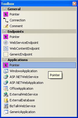
Figure 5-6 The Application Designer toolbox
You work with the Application Designer by dragging application prototypes onto the design surface and connecting the resulting application to define the connected system. You can right-click the design surface, select the Add New option and choose from the list of available prototypes. Then you position the newly added application manually.
Some of these base application types, such as ASP.NET applications and Windows applications, support round-trip developing with code. This means that the application design can be implemented, which is to say that code can be generated. Once implemented, changes made to the code are reflected back in the designer, whereas changes made in the designer are also reflected in code. This is a great development feature, especially when the architect and developer are two separate people sitting at two separate keyboards. This is known as code round-tripping.
Config round-tripping is also supported and is similar to code round-tripping, but it applies to changes made to the web.config. Initially, you might not have a web.config file in your project—one is generated only if you make some configuration settings in the Application Designer, such as a security setting. You could also add one manually to your Web project. After that, any changes to the web.config file will be reflected in the SDM properties and therefore in the Application Designer, and vice versa.
TIP
You can also create your own custom prototypes by using the SDK.
Endpoints
Applications communicate through endpoints. For two applications to be connected there must be a provider endpoint at one end of the connection and a consumer endpoint at the other end. You can add additional provider endpoints directly to applications that support them either by dragging them from the toolbox or by right-clicking an application and selecting Add New. Be sure to pick the right endpoint type. To create consumer endpoints you connect an application to a provider endpoint. This creates an endpoint of the right type and configures it with the URL of the target in one go. (This is described in the following section.)
There are four application endpoint types, each of which has provider and consumer forms:
- WebServiceEndpoint
A SOAP-based Web service endpoint. These endpoints also show up on External Web Services and can be used on any other custom application type that supports Web services connectivity, such as a SQL Server 2005 Database.
- WebContentEndpoint
An HTTP-based Web content endpoint for accessing files other than Web services.
- DatabaseEndpoint
Defines a connection to a database.
- GenericEndpoint
An endpoint of unspecified protocol.
TIP
To keep your diagram clean, delete any endpoints that you won't be using. You can hide the labels by right-clicking the endpoint and choosing Hide Label, or by just deleting the label.
Connecting Endpoints
After you've added applications to the diagram, connect them to indicate which communication pathways exist. There are several methods for doing this:
Hold down the Alt key while dragging from one application to another.
Right-click the application and use the Connect option.
Use the connection tool from the toolbox.
TIP
To tidy up the connections, try right-clicking each connection and then selecting Redraw Connection. You can also manually reroute a connection by selecting the connection and then dragging individual line segments into place.
Figure 5-7 shows three ASP.NET Web applications and the properly configured and connected endpoints.
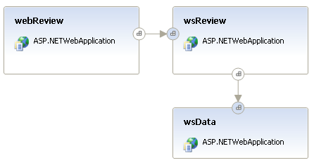
Figure 5-7 An example of an application diagram
Reusing Custom Application Prototypes
As you create and configure applications, you might find that you want to reuse the same—or similar—application definitions in other solutions. Perhaps you have a standard configuration for an ASP.NET application, or maybe a standard set of operations that all Web services should offer. If this is the case, you can create your own custom prototypes and save them to the toolbox. Right-click the item or group of items and use the Add to Toolbox feature. Specify a friendly name and a graphical bitmap image to represent the toolbox item in the toolbox. Visual Studio will save the application as an Application Designer prototypefile (.adprototype). You will be prompted for the file name and path.
TIP
These prototypes are saved in a proprietary format rather than XML, so they are not easily edited. Any changes would have to be done by using the designer and then saving a new prototype.
You are allowed to save the following as prototypes to the toolbox:
Application
Group of applications
Endpoint
Group of endpoints
Later, when you're editing a diagram, you can locate your new application under the Applications or Endpoints sections in the toolbox and drag it onto your design surface. It will have all the same settings and constraints that you gave it initially, and you can change any of them to suit the new application if need be.
NOTE
This form of reuse is based on propagating a copy of the application or endpoint specifications and is very different from reusing an application implementation complete with code. An implemented application can be reused by including it in multiple systems. Systems are not intended to be used in other application diagrams; they serve as an efficient way to deploy many related applications together. You'll learn more about systems and the System Designer later in this chapter.
You can save these prototypes to custom locations on your hard drive and then edit the registry to enable Visual Studio to find them. Refer to the “Reusing Custom Server Prototypes” section previously in this chapter.
Implementing the Classes
When I hear the word implement, I usually envision the process of adding all the code to the class so that it's complete, can be compiled, and can be used by the application. In other words, implementing a class means to construct it. Therefore, it would be safe to say that although the application architect architects a Web service, it's the developer who implements it. This is how the workflow in Team System is set up . . . almost.
In practice it's the architect who gets to use the Implement feature in Team System because that feature is available only in the Team Edition for Software Architects. The architect can right-click a Windows application, Web application, Web service, or Office application and Team System will generate the stub code. What's even better is that Team System supports an Implement All Applications feature, which will generate all the projects and template code for every respective application and service in the diagram. (See Figure 5-8.) This code can then be checked-in to source control, and one or more task work items can be created. This lets the developers know that there's some starter code out there, ready to implement.
TIP
This is a perfect situation in which you may want to install the Team Developer and Team Architect editions together, or Team Suite, on the developer's desktop. For the architect who develops, or the developer who architects, having both editions would be very productive.
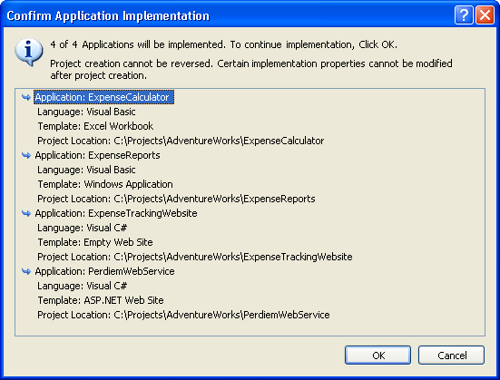
Figure 5-8 Implementing all applications and services at once
Let's not get too far ahead of ourselves here. Before using the productive implement function the application architect might need to specify a few things for the application or service. After you implement the projects there's no going back. Some properties are immutable and cannot be changed. You would have to delete everything and start over. So slow down and plan first. The following properties can and should be set first. (See Figure 5-9.)
Default Class namespace
Language
Name
Project (location)
Template
By default, the implementation is very basic. It's just a skeletal structure, or stub code that gets generated. This is just enough for the architect to take a cursory look, change a few namespaces, reference a few assemblies, add some comments, check it into version control, and then send it on its way to the developers. Figure 5-10 shows the new project that is created.
TIP
Team System allows you to customize these templates. Notice in Figure 5-9 that the Template drop-down control includes an option for Custom. You can define your own custom template, which could be a starter application or an application template that defaults to your company's best practices.
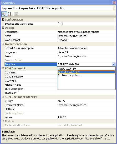
Figure 5-9 Setting implementation properties in the Application Designer
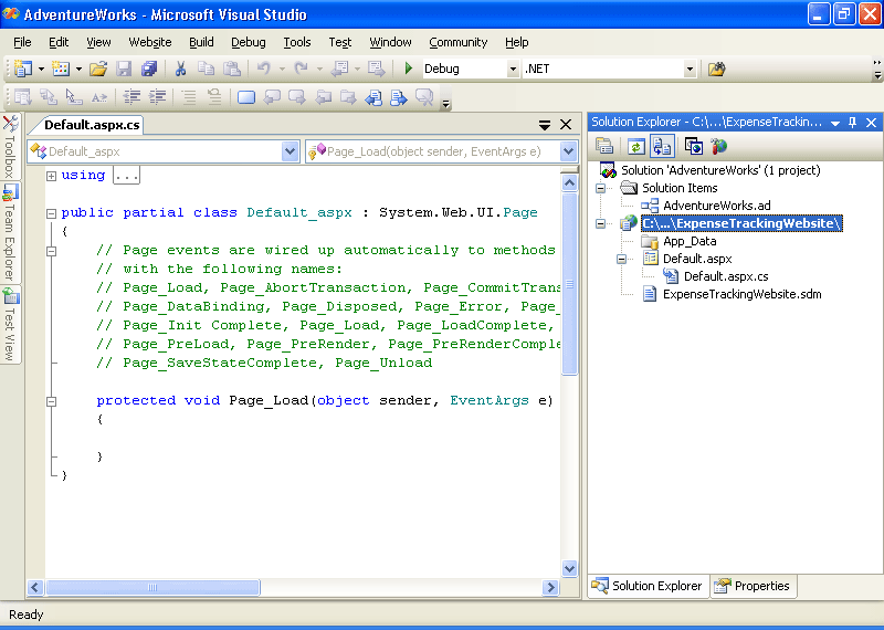
Figure 5-10 The newly implemented ASP.NET project
Team System will also create a System Definition Model (SDM) document, and associate it with the newly created project. This document describes the ASP.NET Web application (or whatever application you implemented). This file is created from the detail that was previously stored in the application diagram. This SDM document will be saved and associated with the Visual Studio project. If you double-click the SDM document it will simply take you back to the application diagram (assuming you have it available in your solution). If, instead, you right-click the document and open it with the XML editor, it will look like the document shown in Figure 5-11. Seeing descriptive XML like this makes you appreciate what SDM and DSI are accomplishing. It also makes you value the designers and their ability to distract you from all of that detail.
TIP
If you are interested in learning about the inner workings of these documents, the schema is documented in the SDK. The SDK also provides examples on how to populate model data.
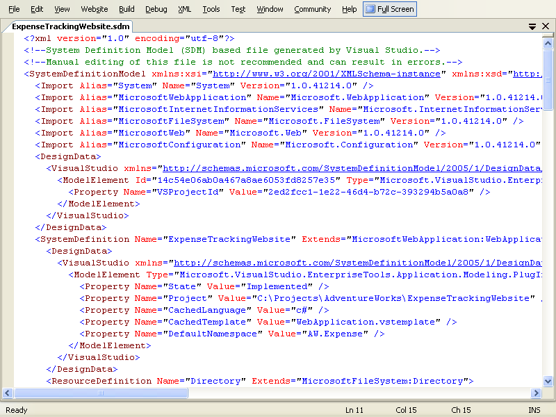
Figure 5-11 The SDM document that is created when you implement an ASP.NET Web application
More Info
For more information about SDM and its association with the Microsoft Dynamic Systems Initiative (DSI), refer to Chapter 3.
EAN: 2147483647
Pages: 97