Installing and Configuring Routing Protocols
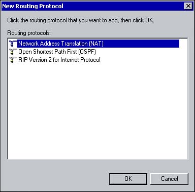
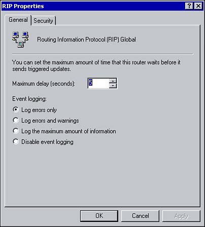
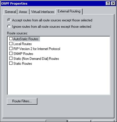
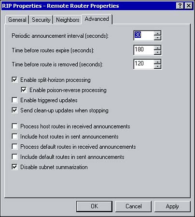
| Once the demand-dial and/or LAN interfaces have been created, the last detail you need to address is to configure the RRAS server as a network router is to configure the appropriate routing protocol interfaces. The following sections explore installing the protocols, and then take a more detailed look at each of the protocol interfaces. You must first add the routing protocol; you right-click the General node and choose New Routing Protocol. The window that appears lists protocols to choose from (see Figure 7.11). Select RIPv2 or OSPF and click OK. Figure 7.11. Adding a new routing protocol to the General node. Configuring Routing ProtocolsOnce RIP or OSPF has been installed, you can configure a general set of properties for each of the protocol types. Because RIP requires little configuration, the Properties window for the protocol has only two tabs, as shown in Figure 7.12. Figure 7.12. Configuring RIP properties. From the General tab, you can configure the Maximum Delay value, which determines how long a router waits to send an update notification message to other routers on the network. The remaining options allow you to set up event logging for the protocol. The Security tab allows you to configure from which routers the local router can accept announcements. Because OSPF is slightly more complex than RIP, it requires more detailed configuration and, as a result, has more options in its Properties window (see Figure 7.13). Figure 7.13. Configuring OSPF properties. From the General tab, the router can be assigned an IP address it can use to identify itself. You can also enable an autonomous system boundary router, which means the router will advertise external routes that it learns from other sources. Using the remaining options, you can enable OSPF event logging. The Areas tab lists all the areas for the router. With OSPF, areas can be used to subdivide a network in order to reduce the size of the database. Routers within an area maintain database information only for the area in which they belong. Using this tab, areas can be added, deleted, and edited. The Virtual Interface tab lists all the configured virtual interfaces. A virtual interface is a virtual connection between an area border router and a backbone area border router. This logical connection allows the two routers to share information. If the Enable Autonomous System Boundary Router option is selected, you can use the External Routing tab to control which sources from which routes are accepted or ignored (see Figure 7.14). The Ignore Filters button defines the specific routes that should be accepted or ignored. Figure 7.14. Configuring external routing settings to configure accepted and ignored routes. Configuring RIP Interface PropertiesEvery RIP interface has it own properties window from which you can configure a number of options. Within the RRAS console, expand IP Routing, RIP, and then right-click one of the available interfaces and click Properties. The General tab allows you to configure the operation mode. You can select auto-static update mode or periodic update mode. With auto-static update, RIP announcements are sent when updates are requested by other routers. Any routes learned while in auto-static update mode are marked as static and remain in the routing table until the administrator manually deletes them. In periodic update mode, announcements are sent out periodically (the Periodic Announcement Interval determines how often). These routes are automatically deleted when the router is stopped and restarted. The outgoing and incoming packet protocol allows you to configure the type of packets, such as RIPv1 or RIPv2, that the router sends out and accepts. The Activate Authentication and Password options allow you to maintain an added level of security. If authentication is enabled, all outgoing and incoming packets must contain the password specified in the password field. When using authentication, make sure that all neighboring routers are configured with an identical password. From the Security tab, an administrator can configure RIP route filters. The router can be configured to send and accept all routes, send and accept routes only from the ranges specified, or to accept and send all routes except for those specified. The Neighbors tab is used to configure how the router interacts with other RIP routers. The Advanced tab (see Figure 7.15) has several configurable options, which are summarized in Table 7.1. Figure 7.15. Configuring Advanced options for a RIP interface. Table 7.1. RIP Advanced Options
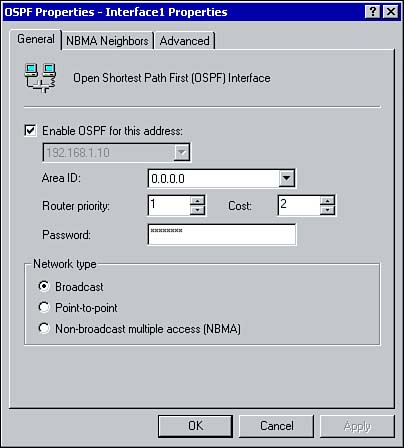
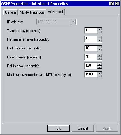
Configuring OSPF Interface PropertiesIf OSPF has been installed, each of the OSPF interfaces can be configured using its Properties window, just as RIP interfaces can be configured. An OSPF interface can be added on the same way as a RIP interface. Simply right-click OSPF under the General node and click New Interface. Select the interface that the protocol will run on and click OK. Figure 7.16 Shows the OSPF properties window that will appear. Figure 7.16. Configuring an OSPF interface via the Properties window. From the General tab, OSPF can be enabled and the area ID, router priority, cost, and password can be configured. The Network Type options allow you to configure whether the OSPF is a broadcast interface, point-to-point interface, or a non-broadcast multiple access interface. The NBMA Neighbors tab allows you to specify the IP address of neighboring routers and associate a priority with the neighbor. Figure 7.17 shows the options available on the Advanced tab, which are summarized in Table 7.2. Figure 7.17. Configuring advanced OSPF options via the Advanced tab.
Table 7.2. OSPF Advanced Options
|

EAN: 2147483647
Pages: 167