Installing, Configuring, and Troubleshooting IP Routing
Installing, Configuring, and Troubleshooting IP RoutingWith Routing and Remote Access (RRAS) , a system running Windows 2000 can function as a network router, which routes packets between networks. This setup allows LANs and WANs to be interconnected . The benefit is that the routing technology is built into the operating system, thus providing small and large businesses with a cost effective and secure way of interconnecting their networks. Some of the features included with RRAS in Windows 2000 include:
The following section looks at the fundamental concepts behind IP routing and discusses how to implement, configure, and troubleshoot IP routing using Windows 2000 Server.
IP RoutingBecause all IP packets have a source and destination IP address, routing is the process of sending a packet from the source address to the destination address. Of course, how the routing of IP packets actually occurs is much more complex. Because each IP packet has addressing information within the header, routers can use this information to determine where a packet should be sent to reach the destination host. Routers maintain information about the physical network, such as the path to a destination network and the metric associated with the route. (The metric is the number of hops, or the number of routers to cross, between the source and destination network.) For routers to know the location to which packets must be forwarded, they must also know about their neighboring routers. This information is stored within the routing table . When a router receives a packet, it checks the routing table to determine where the packet must be sent to reach the destination host. The information within a routing table can be generated statically or dynamically, as you discover in the next sections. Static RoutingWith static routing , an administrator must manually configure the routing table by adding entries that tell the router how to reach other networks. Using the route command, an administrator updates the routing table by specifying the network addresses, the subnet masks, and the metrics associated with each route. When deciding whether to use static routing, keep in mind that it works best for networks that do not change on a regular basis. If the network configuration is constantly changing, the administrative overhead associated with constantly having to update the routing tables greatly increases because the changes must be made on each router. In such cases, it may be more beneficial to implement dynamic routing. Dynamic RoutingDynamic routing eliminates the overhead associated with manually updating routing tables. Routers can dynamically build their own routing tables by communicating with other routers on the network. With dynamic routing, the routing tables are built automatically through router communication. Using a routing communication protocol, routers periodically exchange messages containing location information about routes through the network. This information is used to build and update routing tables. The major advantage of dynamic routing is that it reduces the administrative overhead associated with manually updating routing tables. For example, if a router goes down, the change is automatically propagated to all routers on the network so they are all aware of the change in the network topology. One of the major disadvantages is the amount of traffic that it generates. Routing ProtocolsFor routers to share information and dynamically update their routing tables, a routing protocol must be used. As already mentioned, the two routing protocols supported by Windows 2000 are Routing Information Protocol (RIP) and Open Shortest Path First (OSPF) . Although both routing protocols are used for dynamic routing, there are some distinct differences between the two. Routing Information Protocol (RIP)The Routing Information Protocol (RIP) is designed for small- to medium- sized networks. There are two versions of RIP: RIPv1 and RIPv2. RIPv1 was originally a classful, broadcast-based routing protocol and had no protection; RIPv2 added subnet masking with each route entry, uses multicasts, and provides for a simple authentication scheme. One of the main benefits for choosing RIP is that it's very simple to configure and deploy. One of the major drawbacks associated with this protocol is that it's limited to a maximum hop count of 15. This means any networks more than 15 hop counts away are considered unreachable. Also, as a network increases in size, there can be excessive traffic generated from RIP announcements.
When a router is first configured as a RIP router, the only entries in the routing table are for those networks to which it is physically connected. It then begins to send announcements of its availability to notify other routers of the networks it services. RIPv1 sends the announcements as broadcasts whereas RIPv2 can broadcast multicast packets for the announcements. When changes occur to the network topology, RIPv2 uses triggered updates to communicate the changes to other routers. With triggered updates, the change to the network topology can be propagated immediately.
The Windows 2000 implementation of RIP supports the following features:
Open Shortest Path First (OSPF)OSPF is designed for large internetworks ( especially those spanning more than 15 router hops). The disadvantage of OSPF is that it's generally more complex to set up and requires a certain amount of planning.
OSPF uses the Shortest Path First (SPF) algorithm to calculate routes. The shortest path (the route with the lowest cost) is always used first. Unlike RIP, which only uses announcements to update and share routing information, OSPF maintains a map of the network, known as the link state database . This map is synchronized between adjacent routers, or those neighboring OSPF routers. When a change is made to the network topology, the first router to receive the change sends out a change notification. Each router then updates its copy of the link state database and the routing table is recalculated. One of the main differences between OSPF and RIP is that OSPF divides the network into different areas. Each of the routers maintains information only in the link state database about those areas to which it is connected. Another difference is that OSPF replicates only the changes to the routing table, not the entire table.
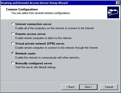
Configuring RRASRouting and Remote Access (RRAS) is installed by default with Windows 2000. Before you can use a Windows 2000 Server as a network router, RRAS must be enabled. To enable RRAS, perform the following steps:
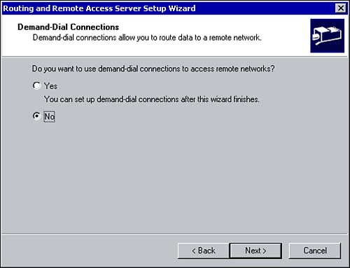
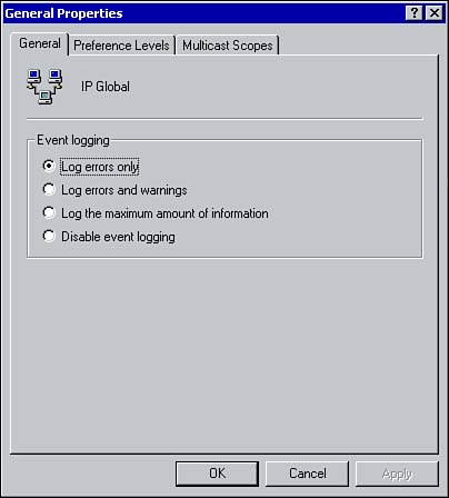
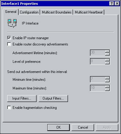
For a server running RRAS to be configured as a network router, you must configure a demand-dial interface (if demand-dialing is required). After demand-dialing is configured, you will assign an IP address to each network interface that will route IP packets, and install and configure one or both of the routing protocols just mentioned. Configuring IP RoutingOnce RRAS has been enabled, some general IP Routing properties can be configured. When you select the General node found under the IP Routing option within the RRAS console, all the known interfaces on the system are displayed. Right-clicking the General node brings up the General Properties window shown in Figure 7.3. Figure 7.3. Configuring IP routing properties via the General Properties window. The configuration options are not overly complex. You can enable or disable logging and specify the type of information to log on the General tab. The Preference Levels tab is used to configure the preference level of different routing sources. For example, routes that are statically configured are given preference over dynamic routes. You can change the preference level of a routing source by selecting the source and using the Move Up or Move Down buttons . Configuring InterfacesThe General node lists all the interfaces available on the system that can be used for IP routing. This includes any LAN interfaces, as well as any demand-dial interfaces. You'll also notice two other ones listed by default: internal and loopback . Summary information is listed about each interface, including the type of interface (such as dedicated or demand-dial), the IP address, and the status of the interface. To view this summary information, expand the RRAS server, IP Routing, and click the General Node. As you will see, each interface has its own set of configurable options (see Figure 7.4). Figure 7.4. Configuring interface properties from an interface's General tab. Use the General tab to configure any of the following options:
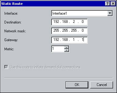
The Configuration tab is used to configure the IP address for the interface. An IP address can be obtained from a DHCP server or a static IP address can be configured. The remaining two tabs are used to configure multicasting. Updating a Windows 2000 Routing Table Using Static RoutesThere might be instances when you need to add a static route to your Windows 2000 router. This, of course, has its advantages and disadvantages. Creating a static route is simple enough to do; however, the routes you configure are not shared between routers. Static routes specify the network address and subnet mask telling the router how to get to a certain destination. The router uses the information to determine which gateway to forward the packet to so it can get to the destination host. Static routes can be configured in one of two ways: using the Route command or through the RRAS management console. Using the Route Add command, static entries can be added to the local routing table on a router (you can also specify whether they should be persistent routesmeaning they will remain in the routing table when the system rebootsby using the p parameter). The syntax for the Route Add command is as follows : route add <destination> mask < netmask > <gateway> metric <interface> The second option is to configure a static route within the RRAS management console. To configure a static route using this method, perform the following steps:
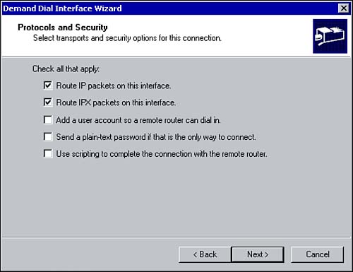
Implementing Demand-Dial RoutingThere are two types of demand-dial connections: on-demand connections and persistent connections . With demand-dial connections, a connection with the remote router is established only when necessary. A connection is established to route information and terminated when the link is not in use. The benefit of this is obviously the cost associated with using a link. With persistent connections, the link does not need to be terminated , even when it is not in use. No additional charges are incurred. Connections between network routers can be one-way initiated or two-way initiated, meaning a connection can be initiated by only one router or by both the routers. With one-way initiated connections, one router is designated as the answering router and the other is designated as the calling router, which is responsible for initiating any connections. Creating a One-Way Demand-Dial InterfaceDemand-dial connections can be created within the Routing and Remote Access snap-in. How you configure the connection depends on whether you are configuring a one-way or two-way initiated connection. To create a demand-dial interface on the calling router, perform the following steps:
The answering router also needs to be configured for one-way demand-dial connections. A user account must be created on the answering router with dial-in permissions and the appropriate policy permissions. The user account is used to authenticate connections from the calling routers. A static route can then be configured on the user account. Also make sure when creating a user account that the Password Never Expires option is selected and the User Must Change Password at Next Logon option is not selected.
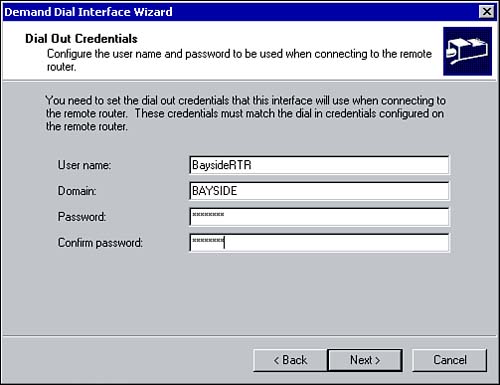
Creating a Two-Way Demand-Dial ConnectionCreating a two-way demand-dial connection is similar to configuring a one-way connection with a few distinct differences. A demand-dial interface is created on each RRAS server using the process outlined previously. You must assign the interface a name, as well as specify the phone number to dial, the device to be used, the protocol and security settings, and the dial-out credentials. A user account must also be configured on each RRAS server with the appropriate remote access permissions. The important thing to keep in mind is that the user account name must be identical to the name assigned to the demand-dial interface of the calling router. Finally, a static route must be configured using the demand-dial interface.
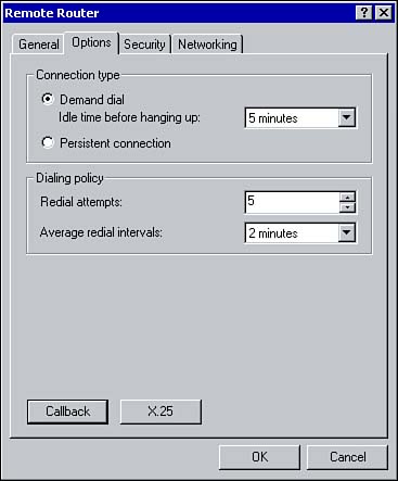
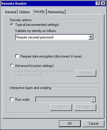
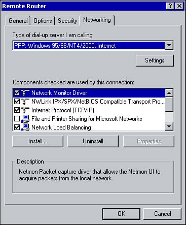
Configuring a Demand-Dial ConnectionOnce a demand-dial connection has been created, you can configure it further using the Properties window for the connection. From the General tab, you can configure the connection device and specify alternative phone numbers to dial. As shown in Figure 7.8, the Options tab is where you configure the connection type: demand-dial or persistent. The dialing policy can also be set by specifying the number of times the calling router will redial if there is no answer and specifying the interval between redial attempts. Figure 7.8. Using the Options tab to configure a connection type. The Security tab enables you to configure the security options for the dial-out connection (see Figure 7.9). This includes whether unsecured passwords are permitted, whether the connection requires data encryption, and whether a script will be run after dialing. Figure 7.9. Configuring security options via the Security tab. As shown in Figure 7.10, the Networking tab is used to configure the type of dial-up server that is dialed in to and the different network components that the connection uses. Figure 7.10. Configuring network settings for a demand-dial connection. There are several other configurations that you can make to a demand-dial interface. Demand-dial filtering allows you to control the type of IP traffic that can initiate a connection. You can allow or deny a connection based on the type of IP traffic. For example, you may only want Web and FTP traffic to initiate the demand-dial connection. Dial-out hours determine the times of day that a connection can be initiated. This allows an administrator to control when the demand-dial connection is used. |
EAN: 2147483647
Pages: 167