Foundation Topics
Layer 2 Switch OperationRecall that with shared Ethernet networks using hubs, many hosts are connected to a single broadcast and collision domain. In other words, shared Ethernet media operate at OSI Layer 1. Each host must share the available bandwidth with every other connected host. When more than one host tries to talk at one time, a collision occurs, and everyone must back off and wait to talk again. This forces every host to operate in half-duplex mode, by either talking or listening at any given time. In addition, when one host sends a frame, all connected hosts hear it. When one host generates a frame with errors, everyone hears that, too. At its most basic level, an Ethernet switch provides isolation from other connected hosts in several ways:
Transparent BridgingA Layer 2 switch is basically a multiport transparent bridge, where each switch port is its own Ethernet LAN segment, isolated from the others. Frame forwarding is based completely on the MAC addresses contained in each frame, such that the switch will not forward a frame unless it knows the destination's location. (When the switch does not know where the destination is, it makes some safe assumptions.) Figure 3-1 shows the progression from a two-port to a multiport transparent bridge, and then to a switch. Figure 3-1. A Comparison of Transparent Bridges and Switches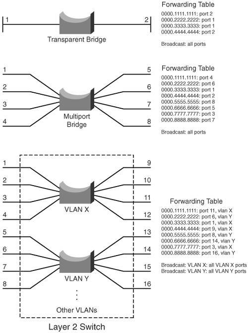 The entire process of forwarding Ethernet frames then becomes figuring out what MAC addresses connect to which switch ports. A switch either must be told explicitly where hosts are located or must learn this information for itself. You can configure MAC address locations through a switch's command-line interface, but this quickly gets out of control when there are many stations on the network or when stations move around. To dynamically learn about station locations, a switch listens to incoming frames and keeps a table of address information. As a frame is received on a switch port, the switch inspects the source MAC address. If that address is not in the address table already, the MAC address, switch port, and virtual LAN (VLAN) on which it arrived are recorded in the table. Learning the address locations of the incoming packets is easy and straightforward. Incoming frames also include the destination MAC address. Again, the switch looks up this address in the address table, hoping to find the switch port and VLAN where the address is attached. If it is found, the frame can be forwarded out that switch port. If the address is not found in the table, the switch must take more drastic actionthe frame is forwarded in a "best effort" fashion by flooding it out all switch ports assigned to the source VLAN. This is known as unknown unicast flooding, with the unicast destination location unknown. Figure 3-2 illustrates this process, using only a single VLAN for simplification. Figure 3-2. Unknown Unicast Flooding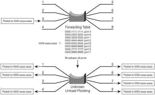 A switch constantly listens to incoming frames on each of its ports, learning source MAC addresses. However, be aware that the learning process is allowed only when the Spanning Tree Protocol (STP) algorithm has decided that a port is stable for normal use. STP is concerned only with maintaining a loop-free network, where frames will not be forwarded recursively. If a loop formed, a flooded frame could follow the looped path, where it would be flooded again and again. In a similar manner, frames containing a broadcast or multicast destination address also are flooded. These destination addresses are not unknownthe switch knows them well. They are destined for multiple locations, so they must be flooded by definition. In the case of multicast addresses, flooding is performed by default. Other more elegant means of determining the destination locations are available and are discussed in Chapter 15, "IP Multicast." Follow That Frame!You should have a basic understanding of the operations that a frame undergoes as it passes through a Layer 2 switch. This helps you get a firm grasp on how to configure the switch for complex functions. Figure 3-3 shows a typical Layer 2 Catalyst switch and the decision processes that take place to forward each frame. Figure 3-3. Operations Within a Layer 2 Catalyst Switch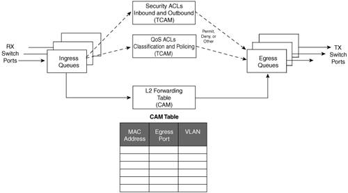 When a frame arrives at a switch port, it is placed into one of the port's ingress queues. The queues each can contain frames to be forwarded, with each queue having a different priority or service level. The switch port then can be fine-tuned so that important frames get processed and forwarded before less important frames. This can prevent time-critical data from being "lost in the shuffle" during a flurry of incoming traffic. As the ingress queues are serviced and a frame is pulled off, the switch must figure out not only where to forward the frame, but also whether it should be forwarded and how. Three fundamental decisions must be made: one concerned with finding the egress switch port, and two concerned with forwarding policies. All these decisions are made simultaneously by independent portions of switching hardware and can be described as follows:
The CAM and TCAM tables are discussed in greater detail in the "Content Addressable Memory" and "Ternary Content Addressable Memory" sections, later in this chapter. After the CAM and TCAM table lookups have occurred, the frame is placed into the appropriate egress queue on the appropriate outbound switch port. The egress queue is determined by QoS values either contained in the frame or passed along with the frame. Like the ingress queues, the egress queues are serviced according to importance or time criticality; frames are sent out without being delayed by other outbound traffic. Multilayer Switch OperationCatalyst switches, such as the 3560 (with the appropriate Cisco IOS Software image), 4500, and 6500, also can forward frames based on Layer 3 and 4 information contained in packets. This is known as multilayer switching (MLS). Naturally, Layer 2 switching is performed at the same time because even the higher-layer encapsulations still are contained in Ethernet frames. Types of Multilayer SwitchingCatalyst switches have supported two basic generations or types of MLS: route caching (first generation MLS) and topology based (second-generation MLS). This section presents an overview of both, although only the second generation is supported in the Cisco IOS Software based switch families, such as the Catalyst 3560, 4500, and 6500. You should understand the two types and the differences between them:
Follow That Packet!The path that a Layer 3 packet follows through a multilayer switch is similar to that of a Layer 2 switch. Obviously, some means of making a Layer 3 forwarding decision must be added. Beyond that, several, sometimes unexpected, things can happen to packets as they are forwarded. Figure 3-4 shows a typical multilayer switch and the decision processes that must occur. Packets arriving on a switch port are placed in the appropriate ingress queue, just as in a Layer 2 switch. Figure 3-4. Operations Within a Multilayer Catalyst Switch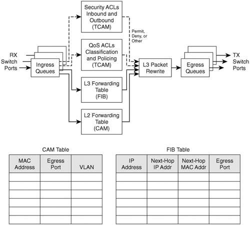 Each packet is pulled off an ingress queue and inspected for both Layer 2 and Layer 3 destination addresses. Now, the decision of where to forward the packet is based on two address tables, whereas the decision of how to forward the packet still is based on access list results. As in Layer 2 switching, all these multilayer decisions are performed simultaneously in hardware:
As with Layer 2 switching, the packet finally must be placed in the appropriate egress queue on the appropriate egress switch port. However, recall that during the multilayer switching process, the next-hop destination was obtained from the FIB table, just as a router would do. The Layer 3 address identified the next hop and found its Layer 2 address. Only the Layer 2 address would be used, so the Layer 2 frames could be sent on. The next-hop Layer 2 address must be put into the frame in place of the original destination address (the multilayer switch). The frame's Layer 2 source address also must become that of the multilayer switch before it is sent on to the next hop. As any good router must do, the Time-To-Live (TTL) value in the Layer 3 packet must be decremented by one. Because the contents of the Layer 3 packet (the TTL value) have changed, the Layer 3 header checksum must be recalculated. And because both Layer 2 and 3 contents have changed, the Layer 2 checksum must be recalculated. In other words, the entire Ethernet frame must be rewritten before it goes into the egress queue. This also is accomplished efficiently in hardware. Multilayer Switching ExceptionsTo forward packets using the simultaneous decision processes described in the preceding section, the packet must be "MLS-ready" and must require no additional decisions. For example, CEF directly can forward most IP packets between hosts. This occurs when the source and destination addresses (both MAC and IP) are known already and no other IP parameters must be manipulated. Other packets cannot be directly forwarded by CEF and must be handled in more detail. This is done by a quick inspection during the forwarding decisions. If a packet meets criteria such as the following, it is flagged for further processing and sent to the switch CPU for process switching:
Note On the Catalyst 6500, both IP and IPX packets are CEF-switched in hardware. All other protocols are handled by process switching on the MSFC module (the routing CPU). On the Catalyst 4500, only IP packets are CEF-switched in hardware. All other routable protocols, including IPX, are flagged for process switching by the switch CPU. With the Catalyst 3560, only IP is CEF-switched in hardware. Other non-IP protocols are not routed at all. Instead, they are flagged for fallback bridging, where they are treated as transparently bridged (Layer 2 switched) packets. An external router or multilayer switch must handle any routing that still is needed during fallback bridging. Tables Used in SwitchingCatalyst switches maintain several types of tables to be used in the switching process. The tables are tailored for Layer 2 switching or MLS and are kept in very fast memory so that many fields within a frame or packet can be compared in parallel. Content Addressable MemoryAll Catalyst switch models use a Content Addressable Memory (CAM) table for Layer 2 switching. As frames arrive on switch ports, the source MAC addresses are learned and recorded in the CAM table. The port of arrival and the VLAN both are recorded in the table, along with a time stamp. If a MAC address learned on one switch port has moved to a different port, the MAC address and time stamp are recorded for the most recent arrival port. Then, the previous entry is deleted. If a MAC address is found already present in the table for the correct arrival port, only its time stamp is updated. Switches generally have large CAM tables so that many addresses can be looked up for frame forwarding. However, there is not enough table space to hold every possible address on large networks. To manage the CAM table space, stale entries (addresses that have not been heard from for a period of time) are aged out. By default, idle CAM table entries are kept for 300 seconds before they are deleted. You can change the default setting using the following configuration command: Switch(config)# mac address-table aging-time seconds By default, MAC addresses are learned dynamically from incoming frames. You also can configure static CAM table entries that contain MAC addresses that might not be learned otherwise. To do this, use the following configuration command: Switch(config)# mac address-table static mac-address vlan vlan-id interface type mod/num Here, the MAC address (in dotted triplet hex format) is identified with the switch port and VLAN where it appears. Note You should be aware that there is a slight discrepancy in the CAM table command syntax. Until Catalyst IOS version 12.1(11)EA1, the syntax for CAM table commands used the keywords mac-address-table. In more recent Cisco IOS versions, the syntax has changed to use the keywords mac address-table (first hyphen omitted). The Catalyst 4500 and 6500 IOS Software are exceptions, however, and continue to use the mac-address-table keyword form. What happens when a host's MAC address is learned on one switch port, and then the host moves so that it appears on a different switch port? Ordinarily, the host's original CAM table entry would have to age out after 300 seconds, while its address was learned on the new port. To avoid having duplicate CAM table entries, a switch purges any existing entries for a MAC address that has just been learned on a different switch port. This is a safe assumption because MAC addresses are unique, and a single host should never be seen on more than one switch port unless problems exist in the network. If a switch notices that a MAC address is being learned on alternating switch ports, it generates an error message that flags the MAC address as "flapping" between interfaces. Ternary Content Addressable MemoryIn traditional routing, ACLs can match, filter, or control specific traffic. Access lists are made up of one or more access control entities (ACE), or matching statements that are evaluated in sequential order. Evaluating an access list can take up additional time, adding to the latency of forwarding packets. In multilayer switches, however, all the matching process that ACLs provide is implemented in hardware. TCAM allows a packet to be evaluated against an entire access list in a single table lookup. Most switches have multiple TCAMs so that both inbound and outbound security and QoS ACLs can be evaluated simultaneously, or entirely in parallel with a Layer 2 or Layer 3 forwarding decision. The Catalyst IOS Software has two components that are part of the TCAM operation:
TCAM StructureThe TCAM is an extension of the CAM table concept. Recall that a CAM table takes in an index or key value (usually a MAC address) and looks up the resulting value (usually a switch port or VLAN ID). Table lookup is fast and always based on an exact key match consisting of two input values: 0 and 1 bits. TCAM also uses a table-lookup operation but is greatly enhanced to allow a more abstract operation. For example, binary values (0s and 1s) make up a key into the table, but a mask value also is used to decide which bits of the key are actually relevant. This effectively makes a key consisting of three input values: 0, 1, and X (don't care) bit valuesa three-fold or ternary combination. TCAM entries are composed of Value, Mask, and Result (VMR) combinations. Fields from frame or packet headers are fed into the TCAM, where they are matched against the value and mask pairs to yield a result. As a quick reference, these can be described as follows:
The TCAM always is organized by masks, where each unique mask has eight value patterns associated with it. For example, the Catalyst 6500 TCAM (one for security ACLs and one for QoS ACLs) holds up to 4096 masks and 32,768 value patterns. The trick is that each of the mask-value pairs is evaluated simultaneously, or in parallel, revealing the best or longest match in a single table lookup. TCAM ExampleFigure 3-5 shows how the TCAM is built and used. This is a simple example and might or might not be identical to the results that the Feature Manager produces because the ACEs might need to be optimized or rewritten to achieve certain TCAM algorithm requirements. Figure 3-5. How an Access List Is Merged into TCAM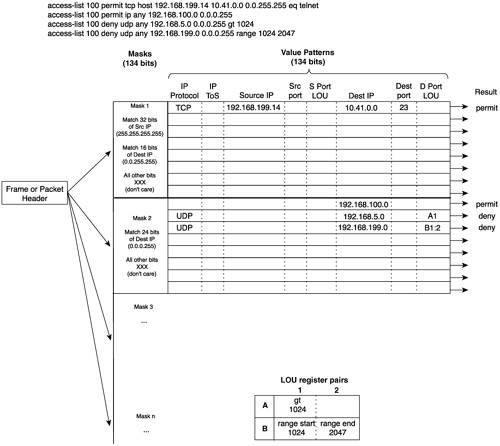 The example access list 100 (extended IP) is configured and merged into TCAM entries. First, the mask values must be identified in the access list. When an address value and a corresponding address mask are specified in an ACE, those mask bits must be set for matching. All other mask bits can remain in the "don't care" state. The access list contains only three unique masks: one that matches all 32 bits of the source IP address (found with an address mask of 0.0.0.0 or the keyword host), one that matches 16 bits of the destination address (found with an address mask of 0.0.255.255), and one that matches only 24 bits of the destination address (found with an address mask of 0.0.0.255). The keyword any in the ACEs means "match anything" or "don't care." The unique masks are placed into the TCAM. Then, for each mask, all possible value patterns are identified. For example, a 32-bit source IP mask (Mask 1) can be found only in ACEs with a source IP address of 192.168.199.14 and a destination of 10.41.0.0. (The rest of Mask 1 is the destination address mask 0.0.255.255.) Those address values are placed into the first value pattern slot associated with Mask 1. Mask 2 has three value patterns: destination addresses 192.168.100.0, 192.168.5.0, and 192.168.199.0. Each of these is placed in the three pattern positions of Mask 2. This process continues until all ACEs have been merged. When a mask's eighth pattern position has been filled, the next pattern with the same mask must be placed under a new mask. A bit of a balancing act occurs to try to fit all ACEs into the available mask and pattern entries without an overflow. Port Operations in TCAMYou might have noticed that matching strictly based on values and masks covers only ACE statements that involve exact matches (either the eq port operation keyword or no Layer 4 port operations). For example, ACEs such as the following involve specific address values, address masks, and port numbers: access-list test permit ip 192.168.254.0 0.0.0.255 any access-list test permit tcp any host 192.168.199.10 eq www What about ACEs that use port operators, where a comparison must be made? Consider the following: access-list test permit udp any host 192.168.199.50 gt 1024 access-list test permit tcp any any range 2000 2002 A simple logical operation between a mask and a pattern cannot generate the desired result. The TCAM also provides a mechanism for performing a Layer 4 operation or comparison, also done during the single table lookup. If an ACE has a port operator, such as gt, lt, neq, or range, the Feature Manager software compiles the TCAM entry to include the use of the operator and the operand in a Logical Operation Unit (LOU) register. Only a limited number of LOUs are available in the TCAM. If there are more ACEs with comparison operators than there are LOUs, the Feature Manager must break up the ACEs into multiple ACEs with only regular matching (using the eq operator). In Figure 3-5, two ACEs require a Layer 4 operation:
The Feature Manager checks all ACEs for Layer 4 operation and places these into Logical Operation Unit (LOU) register pairs. These can be loaded with operations, independent of any other ACE parameters. The LOU contents can be reused if other ACEs need the same comparisons and values. After the LOUs are loaded, they are referenced in the TCAM entries that need them. This is shown by LOUs A1 and the B1:2 pair. A finite number (actually, a rather small number) of LOUs are available in the TCAM, so the Feature Manager software must use them carefully. Troubleshooting Switching TablesIf you see strange behavior in a Catalyst switch, it might be useful to examine the contents of the various switching tables. In any event, you might sometimes need to find out on which switch port a specific MAC address has been learned. CAM Table OperationTo view the contents of the CAM table, you can use the following form of the show mac address-table EXEC command: Switch# show mac address-table dynamic [address mac-address | interface type mod/num | vlan vlan-id] The entries that have been learned dynamically will be shown. You can add the address keyword to specify a single MAC address, or the interface or vlan keywords to see addresses that have been learned on a specific interface or VLAN. For example, assume that you need to find the learned location of the host with MAC address 0050.8b11.54da. The show mac address-table dynamic address 0050.8b11.54da command might produce the output in Example 3-1. Example 3-1. Determining Host Location by MAC AddressSwitch# show mac address-table dynamic address 0050.8b11.54da Mac Address Table ------------------------------------------ Vlan Mac Address Type Ports ---- ----------- ---- ----- 54 0050.8b11.54da DYNAMIC Fa0/1 Total Mac Addresses for this criterion: 1 Switch#From this, you can see that the host somehow is connected to interface FastEthernet 0/1, on VLAN 54. Tip If your Catalyst IOS switch is not accepting commands of the form mac address-table, try adding a hyphen between the keywords. For example, the Catalyst 4500 and 6500 most likely will accept show mac-address-table instead. Suppose that this same command produced no output for the interface and VLAN. What might that mean? Either the host has not sent a frame that the switch can use for learning its location, or something odd is going on. Perhaps, the host is using two network interface cards (NICs) to load-balance traffic; one NIC is only receiving traffic, while the other is only sending. Therefore, the switch never hears and learns the receivingonly NIC address. To see the CAM table's size, use the show mac address-table count command. MAC address totals are shown for each active VLAN on the switch. This can give you a good idea of the size of the CAM table and how many hosts are using the network. Be aware that many MAC addresses can be learned on a switch's uplink ports. CAM table entries can be cleared manually, if needed, by using the following EXEC command: Switch# clear mac address-table dynamic [address mac-address | interface type mod/num | vlan vlan-id] Frequently, you need to know where a user with a certain MAC address is connected. In a large network, discerning at which switch and switch port a MAC address can be found might be difficult. Start at the network's center, or core, and display the CAM table entry for the MAC address. Look at the switch port shown in the entry and move to the neighboring switch connected to that port. Then, repeat the CAM table process. Keep moving from switch to switch until you reach the edge of the network where the MAC address connects. TCAM OperationThe TCAM in a switch is more or less self-sufficient. Access lists are compiled or merged automatically into the TCAM, so there is nothing to configure. The only concept you need to be aware of is how the TCAM resources are being used. TCAMs have a limited number of usable mask, value pattern, and LOU entries. If access lists grow to be large or many Layer 4 operations are needed, the TCAM tables and registers can overflow. If that happens while you are configuring an ACL, the switch will generate syslog messages that flag the TCAM overflow situation as it tries to compile the ACL into TCAM entries. |
EAN: 2147483647
Pages: 177