3-1. Configuring Interfaces Every firewall has one or more interfaces that can be used to connect to a network. To pass and inspect traffic, each firewall interface must be configured with the following attributes: Name IP address and subnet mask (IPv4; beginning with PIX 7.x, IPv6 is also supported) Security level (a higher level is considered more secure)
Traffic is allowed to flow from a higher-security interface to a lower-security interface ("inside" to "outside," for example) as soon as access list, stateful inspection, and address translation require-ments are met. Traffic from a lower-security interface to a higher one must pass additional inspection and filtering checks. Firewall interfaces can be physical, where actual network media cables connect, or logical, where the interface exists internally to the firewall and is passed to a physical trunk link. Each Cisco firewall platform supports a maximum number of physical and logical interfaces. Starting with PIX OS release 6.3, trunk links are also supported. The trunk itself is a physical interface, and the VLANs carried over the trunk are logical VLAN interfaces. A trunk link has the following attributes: Firewall trunk links support only the IEEE 802.1Q trunk encapsulation method. As each packet is sent to a trunk link, it is tagged with its source VLAN number. As packets are removed from the trunk, the tag is examined and removed so that the packets can be forwarded to their appropriate VLANs. 802.1Q trunks support a native VLAN associated with the trunk link. Packets from the native VLAN are sent across the trunk untagged. A firewall doesn't negotiate trunk status or encapsulation with Dynamic Trunking Protocol (DTP); the trunk is either "on" or "off."
Figure 3-1 shows how a trunk link between a firewall and a switch can encapsulate or carry frames from multiple VLANs. Notice that frames from the native VLAN are sent without a tag, and frames from other VLANs have a tag added while in the trunk. Figure 3-1. How an IEEE 802.1Q Trunk Works on a Firewall 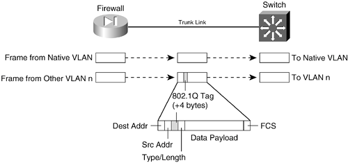
Basic Interface Configuration You should follow the configuration steps in this section for each firewall interface that will be used. By default, interfaces are in the shutdown state and have no IP address assigned. 1. | Survey the available interfaces:
Firewall# show version
Firewall interfaces are referenced by their hardware index and their physical interface names. For example, show version on a PIX 525 running PIX release 6.3 produces the following output:
0: ethernet0: address is 0030.8587.546e, irq 10 1: ethernet1: address is 0030.8587.546f, irq 11 2: gb-ethernet0: address is 0003.4725.2f97, irq 5 3: gb-ethernet1: address is 0003.4725.2e32, irq 11
The first number is the hardware index, which indicates the order in which the interfaces were placed in the firewall backplane. Each physical interface has a hardware ID name that indicates its medium; ethernet0 is a 10/100BASE-TX port, and gb-ethernet0 is a Gigabit Ethernet port.
With PIX 7.x, the output is slightly different:
0: Ext: Ethernet0 : media index 0: irq 10 1: Ext: Ethernet1 : media index 1: irq 11 2: Ext: GigabitEthernet0 : media index 0: irq 5 3: Ext: GigabitEthernet1 : media index 1: irq 11
TIP On an FWSM, all interfaces are logical and have names beginning with vlan followed by the VLAN number. With a default configuration, the only VLAN interfaces available are the ones that have been configured from the Catalyst switch Supervisor module. These are created with the following Catalyst IOS configuration commands: Switch(config)# firewall vlan-group group vlan-list Switch(config)# firewall module mod vlan-group group
Logical interfaces have a hardware ID in the form vlan1, vlan55, and so on. These interfaces are not available until you define them with configuration commands.
At this point, you should identify each of the interfaces you will use. At a minimum, you need one interface as the "inside" of the firewall and one as the "outside." By default, the firewall chooses two interfaces for the inside and outside. You can view the interface mappings with the show nameif EXEC command. You also can change the interface-name mappings as needed.
TIP The show interface command lists each interface along with its state, MAC and IP addresses, and many counters. You can use the output to verify an interface's activity and current settings. The interface state is shown by two values: The configured administrative state (up or administratively down) and the line protocol state (up or down). The line protocol state indicates whether the interface is connected to a live network device. | 2. | Define the interface.
- a. Define a physical interface:
FWSM 2.x | | PIX 6.x | Firewall(config)# interface hardware-id [hardware-speed] [shutdown] | PIX 7.x | [View full width] Firewall(config)# interface hardware-id Firewall(config-if)# speed {auto | 10 | 100 |  nonegotiate} Firewall(config-if)# duplex {auto | full | half} Firewall(config-if)# [no] shutdown nonegotiate} Firewall(config-if)# duplex {auto | full | half} Firewall(config-if)# [no] shutdown
|
The interface is referenced by its hardware-id. For example, this could be gb-ethernet1 in PIX 6.3 or GigabitEthernet1 in PIX 7.x.
In PIX 6.3, the interface medium's speed and duplex mode are given by one of the following hardware-speed values:
1000full | Gigabit Ethernet autonegotiation, advertising full duplex | 1000full nonegotiate | Gigabit Ethernet full duplex with no autonegotiation | 1000auto | Gigabit Ethernet autonegotiation | 100full | 100-Mbps full duplex | auto | Intel 10/100 autonegotiation | 100basetx | 100-Mbps half duplex | 10full | 10-Mbps full duplex | 10baset | 10-Mbps half duplex | bnc | 10-Mbps half duplex with BNC | aui | 10-Mbps half duplex with AUI |
Beginning with PIX 7.x, the interface speed and duplex are configured with separate interface configuration commands. By default, an interface uses autodetected speed and autonegotiated duplex mode.
TIP By default, interfaces are administratively shut down. To enable an interface in PIX 6.3, use the interface configuration command without the shutdown keyword. For PIX 7.x, use the no shutdown interface configuration command. To disable or administratively shut down an interface, add the shutdown keyword. - b. (Optional) Define a logical VLAN interface:
FWSM 2.x | Firewall(config)# interface vlan vlan_id | PIX 6.x | Firewall(config)# interface hardware_id vlan_id logical | PIX 7.x | Firewall(config)# interface hardware_id[.subinterface] Firewall(config-subif)# vlan vlan_id
|
Logical VLAN interfaces must be carried over a physical trunk interface, identified as hardware_id (gb-ethernet0 or GigabitEthernet0, for example). In PIX 6.3, the VLAN interface itself is identified by vlan_id, a name of the form vlanN (where N is the VLAN number, 1 to 4095). The logical keyword makes the VLAN interface a logical one.
In PIX 7.x, a subinterface number is added to the physical interface name to create the logical interface. This is an arbitrary number that must be unique for each logical interface. The VLAN number is specified as vlan_id in a separate vlan subinterface configuration command.
Packets being sent out a logical VLAN interface are tagged with the VLAN number as they enter the physical trunk link. The VLAN number tag is stripped off at the far end of the trunk, and the packets are placed on the corresponding VLAN. The same process occurs when packets are sent toward the firewall on a VLAN.
The trunk encapsulation used is always IEEE 802.1Q, and the tagging encapsulation and unencapsulation are automatically handled at each end of the trunk. Make sure the far-end switch is configured to trunk unconditionally. For example, the following Catalyst IOS switch configuration commands could be used:
Switch(config)# interface gigabitethernet 0/1 Switch(config-if)# switchport Switch(config-if)# switchport trunk encapsulation dot1q Switch(config-if)# switchport mode trunk
By default, any packets that are sent out the firewall's physical interface itself are not tagged, and they appear to use the trunk's native VLAN. These packets are placed on the native VLAN number of the far-end switch port.
If you intend to use logical VLAN interfaces on a physical firewall interface that is trunking, you should never allow the trunk's native VLAN to be used. You can do this by configuring a VLAN number on the physical interface, too. After this is done, the firewall cannot send packets across the trunk untagged.
By default, Cisco switches use VLAN 1 as the native (untagged) VLAN on all trunk links. Be aware that the native VLAN can be set to any arbitrary VLAN number on a switch. Find out what native VLAN is being used, and choose a different VLAN number on the firewall's physical interface.
Also make sure that the switch is using something other than the native VLAN to send packets to and from the firewall. The idea is to use only VLANs that are defined specifically to pass data to and from the firewall while eliminating the possibility that an unexpected VLAN appears on the trunk. For example, you could use the following commands on a Catalyst switch to set a trunk's native VLAN to VLAN 7 and to allow only VLANs 100 through 105 to pass over the trunk to the firewall:
SwitchIconfig)# interface gigabitethernet 1/1 Switch(config-if)# switchport Switch(config-if)# switchport trunk native vlan 7 Switch(config-if)# switchport trunk allowed vlan 100-105 Switch(config-if)# switchport mode trunk
You can use the following configuration command to force the firewall to tag packets on the physical firewall trunk interface, too:
FWSM 2.x | | PIX 6.x | Firewall(config)# interface hardware_id vlan_id physical | PIX 7.x | |
Again, the VLAN is identified by vlan_id, a name of the form vlanN (where N is the VLAN number, 1 to 4095). The physical keyword makes the logical VLAN interface overlay with the physical interface so that any packets passing over the interface receive a VLAN ID tag.
After a VLAN has been assigned to the physical interface, the firewall drops any untagged packets that are received over the trunk interface's native VLAN.
This step is unnecessary beginning with PIX 7.x, because the physical interface is configured with the no nameif command by default, which forces all traffic to pass through one or more subinterfaces that are configured with a VLAN number, requiring a VLAN tag.
TIP After a VLAN number has been assigned to a logical interface, it is possible to change the VLAN number. You can use this PIX 6.3 configuration command to change from the old VLAN name to a new one: Firewall(config)# interface hardware_id change-vlan old-vlan-id new-vlan-id
| 3. | (Optional) Name the interface:
FWSM 2.x | Firewall(config)# nameif vlan-id if_name securitylevel | PIX 6.x | Firewall(config)# nameif {hardware-id | vlan-id} if_name securitylevel | PIX 7.x | Firewall(config)# interface hardware_id[.subinterface] Firewall(config-if)# nameif if_name Firewall(config-if)# security-level level
|
Here, the physical interface is identified by its hardware-id (gb-ethernet0, for example) or vlan-id (vlan5, for example; the word vlan is always present). If multiple-security context mode is being used, the vlan-id or hardware-id could be an arbitrary name that has been mapped to the context by the allocate-interface command in the system execution space.
The interface is given the arbitrary name if_name (1 to 48 characters) that other firewall commands can use to refer to it. By default, the "inside" and "outside" names are predefined to two interfaces. You can change those assignments, and you can use entirely different names if you want.
A security level is also assigned to the interface as securitylevel (where level is a number 0 to 100, from lowest to highest). PIX 7.x is the exception, where the security level is given with the keyword security-level, followed by the level number (0 to 100). Security levels 0 and 100 are reserved for the "outside" and "inside" interfaces, respectively. Other perimeter interfaces should have levels between 1 and 99.
For example, the outside interface could be configured as follows:
FWSM 2.x | Firewall(config)# nameif vlan10 outside security0 | PIX 6.x | Firewall(config)# nameif gb-ethernet0 outside security0 | PIX 7.x | Firewall(config)# interface gigabitethernet0 Firewall(config-if)# nameif outside Firewall(config-if)# security-level 0
|
NOTE Security levels are used only to determine how the firewall inspects and handles traffic. For instance, traffic passing from a higher-security interface toward a lower one is assumed to be going toward a less-secure area. Therefore, it is forwarded with less-stringent policies than traffic coming in toward a higher-security area. In addition, firewall interfaces must have different security levels. The only exceptions are with PIX 7.x and FWSM 2.2+, which allow interfaces to have the same security level only if the same-security-traffic permit inter-interface global configuration command has been used. | 4. | Assign an IP address.
You can assign a static IP address if one is known and available for the firewall. Otherwise, you can configure the firewall to request an address from either a DHCP server or through PPPoE. (Your ISP should provide details about obtaining an address.) Choose one of the following steps:
- a. (Optional) Assign a static address:
Firewall(config)# ip address if_name ip_address [netmask]
If you have a static IP address that the firewall can use, you can assign it here. The interface named if_name (inside or outside, for example) uses the IP address and subnet mask given.
If you omit the netmask parameter, the firewall assumes that a classful network (Class A, B, or C) is being used. For example, if the first octet of the IP address is 1 through 126 (1.0.0.0 through 126.255.255.255), a Class A netmask (255.0.0.0) is assumed. If the first octet is 128 through 191 (128.0.0.0 through 191.255.255.255), a Class B netmask (255.255.0.0) is assumed. If the first octet is 192 through 223 (192.0.0.0 through 223.255.255.255), a Class C netmask (255.255.255.0) is assumed.
If you use subnetting in your network, be sure to specify the correct netmask rather than the classful mask (255.0.0.0, 255.255.0.0, or 255.255.255.0) that the firewall derives from the IP address.
- b. (Optional) Obtain an address via DHCP:
Firewall(config)# ip address outside dhcp [setroute] [retry retry_cnt]
Generally, the outside interface points toward an ISP. Therefore, the firewall can generate DHCP requests from that interface. If no reply is received, the firewall retries the request up to retry_cnt times (4 to 16; the default is 4).
You can also set the firewall's default route from the default gateway parameter returned in the DHCP reply. To do this, use the setroute keyword; otherwise, you have to explicitly configure a default route.
TIP You can release and renew the DHCP lease for the outside interface by entering this configuration command again. - c. (Optional) Obtain an address through PPPoE.
- Define a username for PPPoE authentication: FWSM 2.x | | PIX 6.x | Firewall(config)# vpdn username name password passwd [store-local] | PIX 7.x | |
The firewall authenticates itself with an ISP using a username name (a text string) and password passwd (an unencrypted text string). You can repeat this command to define multiple usernames and passwords if several ISPs are possible. By default, the username and password are entered into the firewall configuration as a part of this command. If you use a management tool such as CiscoWorks Firewall Management Center to deploy the firewall, a template configuration might overwrite a valid username and password. You can choose to store the username and password locally in the firewall's Flash memory by adding the store-local keyword. - (Optional) Define a VPDN group to contain PPPoE parameters: FWSM 2.x | | PIX 6.x | Firewall(config)# vpdn group group_name localname name | PIX 7.x | |
The firewall can associate PPPoE parameters into groups such that one group is used to negotiate with one ISP. Here, the group_name is an arbitrary name (up to 63 characters) that points to a locally defined username name and password pair. This pair should already be configured with the vpdn username name command. - Set the PPPoE authentication method: FWSM 2.x | | PIX 6.x | Firewall(config)# vpdn group group_name ppp authentication {pap | chap | mschap} | PIX 7.x | |
For the VPDN group, you should use the same authentication method that your ISP uses: pap (Password Authentication Protocol, with cleartext exchange of credentials), chap (Challenge Handshake Authentication Protocol, with encrypted exchange), or mschap (Microsoft CHAP, version 1 only). - Enable PPPoE requests using a VPDN group: FWSM 2.x | | PIX 6.x | Firewall(config)# vpdn group group_name request dialout pppoe | PIX 7.x | |
The firewall builds PPPoE requests using the parameters defined in VPDN group group_name. - Request IP address information on the outside interface: FWSM 2.x | | PIX 6.x | Firewall(config)# ip address outside pppoe [setroute] | PIX 7.x | |
The firewall sends PPPoE requests on its outside interface to authenticate and obtain an IP address and subnet mask from the ISP. If the default gateway that is returned should be used as the firewall's default route, add the setroute keyword. Otherwise, a default route must be configured manually on the firewall. You can renegotiate the address parameters with the ISP by entering this configuration command again.
TIP If you already have a static IP address assigned by the ISP, you can use an alternative command: Firewall(config)# ip address outside ip-address netmask pppoe [setroute]
Here, the IP address and netmask are already known. The firewall still authenticates with the ISP through PPPoE, but it uses these values rather than negotiating them. As an example of PPPoE interface configuration, the following commands can be used to define a VPDN group for one ISP that can be used by the firewall:
Firewall(config)# vpdn username JohnDoe password JDsecret Firewall(config)# vpdn group ISP1 localname JohnDoe Firewall(config)# vpdn group ISP1 ppp authentication chap Firewall(config)# vpdn group ISP1 request dialout pppoe Firewall(config)# ip address outside pppoe setroute
| 5. | Test the interface.
- a. Verify the IP address:
Firewall# show ip
or
Firewall# show ip if_name {dhcp | pppoe}
- b. Ping the next-hop gateway address:
Firewall# ping [if_name] ip_address
You can send ICMP echo requests to the next-hop gateway or a host located on the same subnet as the firewall interface. You can specify which firewall interface name to use with if_name, but this isn't required. The target is at ip_address.
If ICMP replies are received, they are reported along with the round-trip time, as in this example:
Firewall# ping 192.168.199.4 192.168.199.4 response received -- 0ms 192.168.199.4 response received -- 30ms 192.168.199.4 response received -- 0ms Firewall#
|
Interface Configuration Examples A PIX Firewall has three interfaces: inside (gb-ethernet0) outside (gb-ethernet1) dmz (gb-ethernet2)
These interfaces have IP addresses 172.16.1.1, 172.17.1.1, and 172.18.1.1, respectively. The configuration commands needed are as follows, for both PIX 6.x and 7.x releases: PIX 6.x | PIX 7.x |
|---|
Firewall(config)# interface gb-ethernet0 1000auto Firewall(config)# interface gb-ethernet1 1000auto Firewall(config)# interface gb-ethernet2 1000auto Firewall(config)# nameif gb-ethernet0 inside security 100 Firewall(config)# nameif gb-ethernet1 outside security 0 Firewall(config)# nameif gb-ethernet2 dmz security 50 Firewall(config)# ip address inside 172.16.1.1 255.255.0.0 Firewall(config)# ip address outside 172.17.1.1 255.255.0.0 Firewall(config)# ip address dmz 172.18.1.1 255.255.0.0
| Firewall(config)# interface gigabitethernet0 Firewall(config-if)# speed auto Firewall(config-if)# duplex auto Firewall(config-if)# nameif inside Firewall(config-if)# security-level 100 Firewall(config-if)# ip address 172.16.1.1 255.255.0.0 Firewall(config)# interface gigabitethernet1 Firewall(config-if)# speed auto Firewall(config-if)# duplex auto Firewall(config-if)# nameif outside Firewall(config-if)# security-level 0 Firewall(config-if)# ip address 172.17.1.1 255.255.0.0 Firewall(config)# interface gigabitethernet2 Firewall(config-if)# speed auto Firewall(config-if)# duplex auto Firewall(config-if)# nameif dmz Firewall(config-if)# security-level 50 Firewall(config-if)# ip address 172.18.1.1 255.255.0.0
|
Now consider the same scenario with an FWSM in slot 3 of a Catalyst 6500 switch. The inside, outside, and dmz interfaces are all logical, as VLANs 100, 200, and 300, respectively: Switch(config)# firewall vlan-group 1 100,200,300 Switch(config)# firewall module 3 vlan-group 1 Switch(config)# exit Switch# session slot 3 processor 1 Firewall# configure terminal Firewall(config)# nameif vlan100 inside security100 Firewall(config)# nameif vlan200 outside security0 Firewall(config)# nameif vlan300 dmz security50 Firewall(config)# ip address inside 172.16.1.1 255.255.0.0 Firewall(config)# ip address outside 172.17.1.1 255.255.0.0 Firewall(config)# ip address dmz 172.18.1.1 255.255.0.0
As a final example, consider a PIX Firewall in a similar scenario. Here, a single physical interface (gb-ethernet0) is configured as a trunk. The inside, outside, and dmz interfaces are all logical, as VLANs 100, 200, and 300, respectively. The configuration commands needed are shown as follows for both the PIX 6.x and 7.x releases: PIX 6.x | PIX 7.x |
|---|
Firewall(config)# interface gb-ethernet0 1000auto Firewall(config)# interface gb-ethernet0 100 physical Firewall(config)# interface gb-ethernet0 200 logical Firewall(config)# interface gb-ethernet0 300 logical Firewall(config)# nameif vlan100 inside security100 Firewall(config)# nameif vlan200 outside security0 Firewall(config)# nameif vlan300 dmz security50 Firewall(config)# ip address inside 172.16.1.1 255.255.0.0 Firewall(config)# ip address outside 172.17.1.1 255.255.0.0 Firewall(config)# ip address dmz 172.18.1.1 255.255.0.0
| Firewall(config)# interface gigabitethernet0 Firewall(config-if)# speed auto Firewall(config-if)# duplex auto Firewall(config-if)# no nameif Firewall(config-if)# interface gigabitethernet0.1 Firewall(config-if)# vlan 100 Firewall(config-if)# nameif inside Firewall(config-if)# security-level 100 Firewall(config-if)# ip address 172.16.1.1 255.255.0.0 Firewall(config-if)# interface gigabitethernet0.2 Firewall(config-if)# vlan 200 Firewall(config-if)# nameif outside Firewall(config-if)# security-level 0 Firewall(config-if)# ip address 172.17.1.1 255.255.0.0 Firewall(config)# interface gigabitethernet0.3 Firewall(config-if)# vlan 300 Firewall(config-if)# nameif dmz Firewall(config-if)# security-level 50 Firewall(config-if)# ip address 172.18.1.1 255.255.0.0
|
In the PIX 6.x configuration, notice that VLAN 100 has been configured on the "physical" portion of the gb-ethernet0 interface. This ensures that VLAN 100 is tagged on the trunk, along with VLANs 200 and 300. In fact, nothing is sent or received untagged on the firewall's trunk. To configure similar behavior in PIX 7.x, the no nameif command is added to the physical interface (gigabitethernet0) configuration. In effect, this prevents the physical interface from becoming active, other than carrying VLAN traffic as a trunk link. Configuring IPv6 on an Interface Beginning with PIX 7.x, firewall interfaces can be configured with an IPv6 address in addition to a traditional IPv4 address. IPv6 addresses are 128 bits longmuch longer than a 32-bit IPv4 address! As well, the IPv6 address format is very different and can be written in the following ways: In full hexadecimal format, the address is written as eight groups of four hexadecimal digits, with colons separating the groups. For example, 1111:2222:3333:4444:5555:6666:7777:8888 represents a single IPv6 host. Leading 0s can be omitted in any group. For example, 1111:0200:0030:0004:5555:6666:7777:8888 can also be written as 1111:200:30:4:5555:6666:7777:8888. Because IPv6 addresses are so long and the address space is so large, addresses with many embedded 0s are common. Therefore, you can abbreviate any number of contiguous 0s as a double colon (::), even if the 0s cross a digit group boundary. For example, 1111:0:0:0:0:0:0:8888 could also be written as 1111::8888. This abbreviation can be used only once in an address, however. IPv6 addresses can also be shown with a network prefix. This specifies how many most-significant bits are used to represent a network address. This is very similar to IPv4 addresses, where the address and prefix values are separated by a slash (/). For IPv6, this format is also ipv6_address/prefix_length, where the prefix length is a value from 1 to 128 bits.
Each firewall interface can potentially have three different IPv6 addresses configured: Link-local address An address that is unique on a network connection to other devices. This is used only for IPv6 neighbor discovery, address autoconfiguration, and administrative uses. A firewall can't forward packets that have link-local addresses as the destination. The address format consists of the following components: - FE80 in the 10 most-significant bits - 54 bits of 0s - 64 bits of host addressing in the modified EUI-64 format
Site-local address A unique address within the site network that cannot be routed outside the site. The address consists of the following components: - FEC0 in the 10 most-significant bits - 38 bits of 0s - 16 bits of subnet ID addressing - 64 bits of host addressing
Global address A globally unique address that can be routed outside the local link and local network. The address consists of the following components: - 001 in the 3 most-significant bit positions - 45 bits of provider addressing (unique to each service provider) - 16 bits of site or subnet addressing (unique only within the local site network) - 64 bits of host addressing (48 bits usually come from the MAC address)
After you configure IPv6 addresses and routing information, the firewall can begin to statefully inspect traffic using IPv6. The following inspection engines are equipped to inspect either IP version: You can follow these steps to configure IPv6 on your firewall: 1. | Select a firewall interface:
Firewall(config)# interface hardware-id
The interface is identified by its hardware-id, which is the full interface type and number or an abbreviated version. For example, GigabitEthernet 0, GigabitEthernet0, and gig0 all refer to the same interface.
| 2. | Assign an IPv6 address to an interface.
- a. (Optional) Use autoconfiguration to derive interface addresses.
A firewall can use stateless autoconfiguration to derive link-local and global addresses for an interface. Use the following commands to enable autoconfiguration:
Firewall(config-if)# ipv6 address autoconfig Firewall(config-if)# ipv6 enable
The firewall first creates a link-local address for the interface. This can be done without any knowledge of surrounding networks or neighboring devices. The link-local address is formed as follows, building digits from least- to most-significant (right to left):
The three least-significant octets are the three least-significant octets of the MAC address. The fixed value ff:fe is always placed in the fifth and fourth least-significant octets. The three most-significant octets of the MAC address become the three next-most-significant octets of the link-local address.
In addition, the next-to-least-significant bit of the most-significant MAC address byte is set to 1. For example, 0003.47 would become 0203.47.
The most-significant address digits always begin with FE80.
For example, consider the following firewall interface. You can use the show interface command to display the interface's MAC address, which is 0003.4708.ec54. When the autoconfiguration is complete, the IPv6 link-local address can be seen with the show ipv6 interface command. Here, the link-local address has become fe80::203:47ff:fe08:ec54:
Firewall# show interface gigabitethernet 1.2 Interface GigabitEthernet1.2 "inside", is up, line protocol is up VLAN identifier 2 MAC address 0003.4708.ec54, MTU 1500 IP address 192.168.198.1, subnet mask 255.255.255.0 Received 1482892 packets, 81328736 bytes Transmitted 311834 packets, 24639862 bytes Dropped 1060893 packets Firewall# Firewall# show ipv6 interface inside inside is up, line protocol is up IPv6 is enabled, link-local address is fe80::203:47ff:fe08:ec54 No global unicast address is configured Joined group address(es): ff02::1 ff02::2 ff02::1:ff08:ec54 [output omitted]
The global interface address has a similar form, but it begins with the prefix learned from a neighboring router. A modified EUI-64 address is used, which includes the ff:fe and MAC address portions.
After a prefix has been learned from router advertisements, you can display the global address with the show ipv6 interface command, as in the following example:
Firewall# show ipv6 interface inside inside is up, line protocol is up IPv6 is enabled, link-local address is fe80::203:47ff:fe08:ec54 Global unicast address(es): 1999::203:47ff:fe08:ec54, subnet is 1999::/64 [AUTOCONFIG] valid lifetime 2591959 preferred lifetime 604759 Joined group address(es): ff02::1 ff02::2 ff02::1:ff08:ec54 [output omitted]
- b. (Optional) Specify a link-local address:
Firewall(config-if)# ipv6 address ipv6_address link-local
You can assign a specific link-local address as ipv6_address if autoconfiguration is not wanted.
- c. (Optional) Specify a complete global IPv6 address:
Firewall(config-if)# ipv6 address ipv6_address/prefix_length [eui-64]
You can specify the complete global address as ipv6_address. The prefix_length (1 to 128) specifies the number of most-significant address bits reserved for the network address. The global address must be unique within the IPv6 network.
You can also use the eui-64 keyword to let the firewall build a unique modified EUI-64 address format. The ipv6_address value is used for the upper 64 bits. The lower 64 bits of the address are the upper three octets of the interface MAC address, ff:fe, and the lower three MAC address octets.
| 3. | Use IPv6 neighbor discovery to learn about neighboring devices.
A firewall can participate in IPv6 neighbor discovery to learn about other directly connected devices. Neighbor discovery is always enabled. You can follow these steps to adjust the neighbor discovery operation:
- a. (Optional) Set the neighbor solicitation interval:
Firewall(config-if)# ipv6 nd ns-interval value
The firewall sends neighbor solicitation messages at the interval value (1000 to 3,600,000 milliseconds [ms]; the default is 1000 ms or 1 second).
- b. (Optional) Set the neighbor reachability time:
Firewall(config-if)# ipv6 nd reachable-time value
If the neighboring device becomes unreachable, the firewall can send neighbor solicitation messages in an attempt to get a response. The firewall waits for value milliseconds (0 to 3,600,000; the default is 0) before declaring the neighbor unreachable. A value of 0 means that the firewall advertises an unspecified reachability time to its neighbors and does not measure this time itself.
- c. (Optional) Adjust duplicate address detection (DAD):
Firewall(config-if)# ipv6 nd dad attempts value
A firewall attempts to check to see if another device is using its own interface link-local address. If a duplication is detected, no IPv6 data is processed on the interface.
If the link-local address is not duplicated, the firewall checks for a duplicate of its interface global IPv6 address.
The firewall sends value (0 to 600; the default is 1) neighbor solicitation messages to detect a duplicate address. If value is set to 0, no DAD is performed.
TIP If a directly connected IPv6 neighbor can't be discovered automatically, you can define it as a static entry. Use the following global configuration command to define and locate the neighboring device: Firewall(config)# ipv6 neighbor ipv6_address if_name mac_address
The neighbor uses the local data-link address ipv6_address and MAC address mac_address (xxxx.xxxx.xxxx hex format). As well, the neighbor can be found on the firewall interface named if_name (outside, for example). Suppose a neighboring device connected to the inside interface uses IPv6 local data-link address fe80::206:5bff:fe02:a841 and MAC address 0006.5b02.a841. You could use the following command to define a static neighbor entry: Firewall(config)# ipv6 neighbor fe80::206:5bff:fe02:a841 inside 0006.5b02.a841
| 4. | Configure IPv6 router advertisements on the interface.
As a Layer 3 IPv6 device, a firewall can participate in router advertisements so that neighboring devices can dynamically learn a default router address. You can follow these steps to configure how the firewall carries out its router advertisement process:
- a. (Optional) Stop sending router advertisements:
Firewall(config-if)# ipv6 nd suppress-ra
By default, a firewall acts as an IPv6 router if IPv6 is enabled and the interface has an IPv6 address. The firewall sends periodic router advertisements to neighboring IPv6 devices, announcing itself as a router.
You can use the ipv6 nd suppress-ra command to stop sending router advertisements. In this case, the firewall appears as a regular IPv6 neighbor or node. Neighbor discovery is active even when router advertisements are suppressed.
- b. (Optional) Set the router advertisement interval:
Firewall(config-if)# ipv6 nd ra-interval [msec] value
By default, a firewall sends router advertisements out an IPv6 interface every 200 seconds. You can adjust the interval to value (3 to 1800 seconds, or 500 to 1,800,000 milliseconds if the msec keyword is given).
- c. (Optional) Adjust the lifetime of router advertisements:
Firewall(config-if)# ipv6 nd ra-lifetime seconds
By default, router advertisements are sent with a valid lifetime of 1800 seconds. Neighboring devices can expect the firewall to be a default router for the duration of the lifetime value.
You can adjust the lifetime to seconds (0 to 9000 seconds). A value of 0 indicates that the firewall shouldn't be considered a default router on the advertising interface.
| 5. | (Optional) Configure IPv6 prefixes to advertise.
By default, a firewall advertises the prefix from any IPv6 address that is configured on an interface. The prefix advertisement can be used by neighboring devices to autoconfigure their interface addresses.
In the commands covered in Steps 5a through 5d, you can use the default keyword to define lifetimes for all prefixes that are advertised. Otherwise, you can specify an IPv6 prefix as ipv6_address/prefix_length. The prefix_length is the number of the most-significant bits used as a network prefix, from 1 to 128.
You can also add the no-autoconfig keyword to advertise that the prefix should not be used for autoconfiguration. By default, any prefix that is advertised is assumed to be "on link," meaning that it is used on the advertising interface. You can add the off-link keyword to specify a prefix that is not configured on the firewall interface.
- a. (Optional) Advertise a prefix with default lifetime values:
Firewall(config-if)# ipv6 nd prefix {default | ipv6_address/prefix_length} [no-autoconfig] [off-link]
By default, the prefix is advertised with a valid lifetime of 30 days (2,592,000 seconds) and a preferred lifetime of 7 days (604,800 seconds).
For example, the following command causes the IPv6 prefix 1999::/64 to be advertised with the default values:
Firewall(config)# ipv6 nd prefix 1999::/64
- b. (Optional) Advertise a prefix with predefined lifetime values:
Firewall(config-if)# ipv6 nd prefix {default | ipv6_address/prefix_length} valid_lifetime preferred_lifetime [no-autoconfig] [off-link]
The prefix is advertised with a valid lifetime of valid_lifetime (0 to 4,294,967,295 or infinite seconds). The prefix also is advertised as a preferred prefix lasting preferred_lifetime (0 to 4,294,967,295 or infinite seconds).
To advertise the prefix 1999::/64 with a valid lifetime of 5 days (432,000 seconds) and a preferred lifetime of 1 day (86,400 seconds), you could use the following command:
Firewall(config)# ipv6 nd prefix 1999::/64 432000 86400
- c. (Optional) Advertise a prefix with an expiration date:
Firewall(config-if)# ipv6 nd prefix {default | ipv6_address/prefix_length} at valid_date_time preferred_date_time [no-autoconfig] [off-link]
The prefix is advertised to remain valid until the specific date and time are reached. The valid lifetime is given as valid_date_time, and the prefix is preferred until preferred_date_time is reached.
Each date and time value is given in this form:
{month day | day month} hh:mm
The month is the month name, given as at least three characters. The day is 1 to 31. The time is always given in 24-hour format.
For example, suppose the prefix 1999::/64 is advertised to expire at 23:59 on December 31 for the valid and preferred lifetimes. You could use the following command to accomplish this:
Firewall(config)# ipv6 nd prefix 1999::/64 dec 31 23:59 dec 31 23:59
- d. (Optional) Don't advertise a prefix:
Firewall(config-if)# ipv6 nd prefix {default | ipv6_address/prefix_length} no-advertise
The prefix given is not advertised.
|
Testing IPv6 Connectivity As soon as you configure IPv6 operation on a firewall, make sure each of the respective interfaces has an IPv6 address. An interface must have a link-local address to communicate with its neighbors. An interface must also have a global address to be able to forward packets to other IPv6 destination addresses. You can display these addresses with the show ipv6 interface command. You can display any other IPv6 routers that the firewall has discovered from router advertisements it has received. Confirm any entries seen with the show ipv6 routers command, as in the following example: Firewall# show ipv6 routers Router fe80::260:70ff:fed7:8800 on inside, last update 1 min Hops 64, Lifetime 1800 sec, AddrFlag=0, OtherFlag=0, MTU=1500 Reachable time 0 msec, Retransmit time 0 msec Prefix 1999::/64 onlink autoconfig Valid lifetime 2592000, preferred lifetime 604800 Firewall#
From the fe80 digits in the most-significant IPv6 address positions, you can distinguish the router address shown as a link-local address. You can also use a form of the ping command to send IPv6 ICMP echo packets to a neighboring device with the following simplified syntax: Firewall# ping [if_name] ipv6_address
With the preceding router example, you could ping the router's IPv6 link-local address to determine good connectivity and a working IPv6 configuration. The following example shows a successful ping series of echo and echo-reply packets: Firewall# ping fe80::260:70ff:fed7:8800 Sending 5, 100-byte ICMP Echos to fe80::260:70ff:fed7:8800, timeout is 2 seconds: Interface must be specified for link-local or multicast address Success rate is 0 percent (0/1) Firewall#
Because a link-local address is being used as the ping target, the firewall cannot determine which of its interfaces to use. This is because link-local addresses don't include any network or route information that could be used to find a destination interface. The example is repeated with the interface information as follows: Firewall# ping inside fe80::260:70ff:fed7:8800 Sending 5, 100-byte ICMP Echos to fe80::260:70ff:fed7:8800, timeout is 2 seconds: !!!!! Success rate is 100 percent (5/5), round-trip min/avg/max = 1/1/1 ms Firewall#
Configuring the ARP Cache A firewall maintains a cache of Address Resolution Protocol (ARP) entries that are learned when it overhears ARP request or ARP reply packets on its interfaces. ARP is used to resolve a host's MAC address based on its IP address, and vice versa. You can use the following commands to configure ARP operations: 1. | Define a static ARP entry:
Firewall(config)# arp if_name ip_address mac_address [alias]
ARP entries normally are created as the firewall hears responses to ARP requests on each interface. There might be times when you need to configure a static entry for hosts that don't answer ARP requests on their interfaces. Static ARP entries don't age out over time.
Specify the firewall interface name if_name (inside or outside, for example) where the host can be found. The host's IP address and MAC address (in dotted-triplet format) must also be given.
Use the alias keyword to create a static proxy ARP entry, where the firewall responds to ARP requests on behalf of the configured host IP addresswhether or not it actually exists.
For example, you can use the following command to configure a static ARP entry for a machine that can be found on the inside interface. Its MAC address and IP address are 0006.5b02.a841 and 192.168.1.199, respectively:
Firewall(config)# arp inside 0006.5b02.a841 192.168.1.199
| 2. | Set the ARP persistence timer:
Firewall(config)# arp timeout seconds
ARP entries dynamically collected are held in the firewall's cache for a fixed length of time. During this time, no new ARP information is added or changed for a specific cached host address. By default, ARP entries are held for 14,400 seconds (4 hours). You can set the persistence timer to seconds (1 to 1,215,752 seconds for PIX 6.3 or 60 to 4,294,967 seconds for PIX 7.x).
You can display the current ARP cache contents with the following command:
Firewall# show arp [statistics]
For example, the following ARP entries have been created on a firewall:
Firewall# show arp stateful 192.168.199.1 0030.8587.546e lan-fo 192.168.198.2 0030.8587.5433 outside 12.16.11.1 0003.4725.2f97 outside 12.16.11.2 0005.5f93.37fc outside 12.16.11.3 00d0.01e6.6ffc inside 192.168.1.1 0003.4725.2e32 inside 192.168.1.4 00d0.0457.3bfc inside 192.168.1.3 0007.0d55.a80a Firewall#
Be aware that the firewall maintains ARP entries for its own interfaces too, as indicated by the gray shaded entries.
You can add the statistics keyword to display counters for various ARP activities. Consider the following output:
Firewall# show arp statistics Number of ARP entries: PIX : 11 Dropped blocks in ARP: 10 Maximum Queued blocks: 17 Queued blocks: 0 Interface collision ARPs Received: 0 ARP-defense Gratuitous ARPS sent: 0 Total ARP retries: 70 Unresolved hosts: 0 Maximum Unresolved hosts: 2 Firewall#
|
TIP If a host's IP address changes or its network interface is replaced, an existing ARP entry can become stale and will be stuck in the firewall's ARP table until it expires. If this happens, you can clear the entire ARP cache contents by using the clear arp EXEC command. If you decide to clear the ARP cache, you should do so only during a maintenance time when the network is not busy; otherwise, there might be a pause in network traffic passing through the firewall while the ARP cache is being rebuilt. Although you can't clear individual ARP cache entries, you can configure a static ARP entry for the IP address in question so that it is paired with a bogus MAC address. After that's done, remove the command that was just used. The bogus static ARP entry is removed, and the firewall relearns an ARP entry based on dynamic information from the host.
Configuring Interface MTU and Fragmentation By default, any Ethernet interface has its maximum transmission unit (MTU) size set to 1500, which is the maximum and expected value for Ethernet frames. If a packet is larger than the MTU, it must be fragmented before being transmitted. You can use the following command to adjust an interface MTU: Firewall(config)# mtu if_name bytes
If you need to, you can adjust the MTU of the interface named if_name to the size bytes (64 to 65,535 bytes). In some cases, you might need to reduce the MTU to avoid having to fragment encrypted packets where the encryption protocols add too much overhead to an already maximum-sized packet. Cisco firewalls can participate in MTU discovery along an end-to-end IP routing path. This process follows RFC 1191, where the MTU is set to the smallest allowed MTU along the complete path. You can display the current MTU configuration for all firewall interfaces by using the show mtu (PIX 6.3) or show running-config mtu (PIX 7.x) command. Interface MTU settings are also displayed as a part of the show interface EXEC command output. For example, the following output represents the MTU settings on a firewall's outside interface: Firewall# show running-config mtu mtu outside 1500 mtu inside 1500 mtu dmz 1500 Firewall# Firewall# show interface Interface GigabitEthernet0 "", is up, line protocol is up Hardware is i82542 rev03, BW 1000 Mbps (Full-duplex), Auto-Speed(1000 Mbps) Available but not configured via nameif MAC address 0003.4708.ec54, MTU not set IP address unassigned 17786900 packets input, 21111200936 bytes, 0 no buffer Received 171 broadcasts, 0 runts, 0 giants 0 input errors, 0 CRC, 0 frame, 0 overrun, 0 ignored, 0 abort 131444 packets output, 89823504 bytes, 0 underruns 0 output errors, 0 collisions 0 late collisions, 191 deferred input queue (curr/max blocks): hardware (0/25) software (0/0) output queue (curr/max blocks): hardware (0/5) software (0/0) Interface GigabitEthernet1.2 "outside", is up, line protocol is up VLAN identifier 2 MAC address 0003.4708.ec54, MTU 1500 IP address 10.1.1.1, subnet mask 255.0.0.0 Received 17683308 packets, 20714401393 bytes Transmitted 119650 packets, 86481250 bytes Dropped 95017 packets [output for other interfaces omitted]
Notice that the outside interface is actually a logical interface (GigabitEthernet1.2) representing a VLAN on a physical trunk interface (GigabitEthernet1). An MTU is set only when the nameif command has been configured for an interface, as in the case of the logical interface named outside. TIP Hosts using TCP connections can also negotiate the maximum segment size (MSS) that is used. This is done as a TCP connection is initiated, and it occurs on a per-connection basis. As a result, an MSS value can sometimes be chosen that is larger than the MTU being used along the path. This also results in TCP packets being fragmented so that they can be forwarded. You can configure the firewall to govern the maximum MSS value negotiated on connections passing through it. The firewall overrides any request for an MSS value larger than its limit, and it replaces the MSS value in the TCP packet so that the negotiation is transparent to the end hosts. You can use the following command to limit the TCP MSS size in all TCP connections: Firewall(config)# sysopt connection tcpmss [minimum] bytes By default, the TCP MSS must be between 48 and 1380 bytes. You can adjust the maximum MSS limit to bytes or the minimum MSS to minimum bytes.
When a firewall receives packets that have been fragmented, it stores each fragment in a cache and virtually reassembles the fragments so that the original packet can be inspected. This allows the firewall to verify the order and integrity of each fragment and to discover malicious exploits that use fragmentation. This process is part of the FragGuard firewall feature. You can configure how the firewall handles the packet fragments it receives with the following steps: 1. | Limit the number of fragments awaiting reassembly:
Firewall(config)# fragment size database-limit [if_name]
By default, a firewall reserves space for 200 fragmented packets in memory per interface, where they are stored temporarily while awaiting reassembly. You can change this to database-limit packets (up to 1,000,000 or the maximum number of free 1550-byte or 16,384-byte blocks). If an interface name isn't specified, the limit applies to all interfaces.
For example, the following command could be used to reserve space for 500 fragments arriving on the outside interface, awaiting virtual reassembly:
Firewall(config)# fragment size 500 outside
TIP You can display the current status of memory blocks with the show block EXEC command. Look for the LOW value for size 1550 and 16,384 to see the fewest free blocks that have been available in the past. In most cases, however, you should keep the reassembly database size set to a low or default value to prevent fragmentation DoS attacks from using large amounts of firewall memory. | 2. | Limit the number of fragments per packet:
Firewall(config)# fragment chain chain-limit [if_name]
By default, a firewall accepts up to 24 fragments of a single packet before they are discarded. You can change this limit to chain-limit (up to 8200 fragments per packet) on a global or per-interface basis. If you do not specify an interface, the chain-limit value is applied to all interfaces.
TIP You might want to consider limiting the fragment space to 1, allowing only a single fragment to be storedthe whole packet itself. Most often, legitimate applications don't fragment packets in the first place, so the firewall shouldn't receive any fragments. Some denial-of-service attacks, on the other hand, exploit the use of fragments. You can use the following command to minimize the fragment cache for all firewall interfaces: Firewall(config)# fragment chain 1
Be aware that such a strict limit causes the firewall to drop packet fragments from legitimate (or desired) traffic too. You should consider increasing the fragment space if you have known applications (Network File System [NFS], for example) or tunneling protocols (GRE, L2TP, or IPSec) that could require the use of fragmentation. | 3. | Limit the time for all parts of a packet to arrive:
Firewall(config)# fragment timeout seconds [if_name]
By default, a firewall collects fragments as they arrive for 5 seconds. If the final fragment doesn't arrive by then, all the fragments are discarded, and the packet is never reassembled. You can adjust the collection time to seconds (up to 30 seconds) on a global or per-interface basis. If an interface name if_name isn't specified, the limit applies to all interfaces.
You can monitor a firewall's fragmentation activity with the show fragment EXEC command. For example, the firewall interface shown in the following output has the default fragment settings (database size 200 packets, chain limit 24 fragments, and timeout limit 5 seconds). The firewall has reassembled 534 packets, and two packets are awaiting reassembly:
Firewall# show fragment outside Interface: outside Size: 200, Chain: 24, Timeout: 5, Threshold: 133 Queue: 2, Assemble: 534, Fail: 1097, Overflow: 12401 Firewall#
You can also see that the reassembly process has failed 1097 times. This is because the timeout limit expired while waiting for all fragments to arrive. The process has also had overflow conditions, indicating that more than 24 fragments arrived on 12,401 different packets.
|
Configuring an Interface Priority Queue In Cisco firewall releases before PIX 7.x, packets are inspected and forwarded in a best-effort fashion. Firewall interfaces have input and output queues or buffers that store inbound or outbound packets temporarily as they arrive at or leave an interface. Sometimes, packets can't be processed quickly enough to keep up with the flow, so they are buffered until they can be serviced. A simple queue structure like this makes for simple interface operation. For example, consider the output queue. The first packet put into the queue is the first one that is taken out and transmitted. There is no differentiation between types of traffic or any quality of service (QoS) requirements. Regardless of the packet contents, packets leave the queue in the same order they went into it. This presents a problem for time-critical data that might pass through a firewall. For example, any type of streaming audio or video must be forwarded in a predictable manner so that packets aren't delayed too much before they reach their destination. Those packets also need to be forwarded at a fairly regular rate; too much variation in packet-to-packet delay (jitter) results in poor-quality audio or video at the destination. When streaming data is mixed with other types of high-volume data passing through a firewall, the nonstreaming data can starve the streaming data flow. This can happen simply because the streaming packets get lost in a sea of other packets competing for transmission time. Beginning with PIX 7.x, a Cisco firewall can support two types of output interface queues: Best-Effort Queue (BEQ) Packets are placed in this queue in an arbitrary order and are transmitted whenever possible. Low-Latency Queue (LLQ) Packets are placed in this queue only when they match specific criteria. Any packets in the LLQ are transmitted ahead of any packets in the BEQ, providing priority service.
In addition, the firewall uses a hardware queue to buffer packets that will be copied directly to the physical interface hardware for transmission. Packets are pulled from the LLQ first, and then the BEQ, and then they are placed in the hardware queue. As soon as the hardware queue is full, those packets are moved into the interface's own buffer for the actual transmission. Figure 3-2 illustrates the interface queues available at each firewall interface, although only the outside interface is shown. Packets that will be sent out an interface are put in the BEQ by default. If a service policy has been configured for the interface, packets that match specific conditions in a class map can be marked for priority service. Only those packets are put into the LLQ. Figure 3-2. Firewall Interface Queue Structure 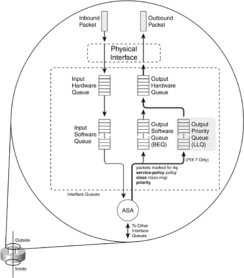
If either the BEQ or LLQ fills during a time of interface congestion, any other packets destined for the queue are simply dropped. In addition, there is no crossover or fallback between queues. If the LLQ is full, subsequent priority packets are not placed in the BEQ; they are dropped instead. You can use the following sequence of steps to configure priority queuing on a PIX 7.x firewall: 1. | Enable the priority queue on an interface:
FWSM 2.x | | PIX 6.x | | PIX 7.x | Firewall(config)# priority-queue if_name |
By default, only a BEQ is enabled and used on each interface. You must specifically enable a priority queue with this command for the interface named if_name (outside, for example).
NOTE Priority queues are supported only on physical interfaces that have been configured with the nameif command. Trunk interfaces and other logical interfaces are not permitted to have a priority queue. Also, priority queues are not supported in multiple-security context mode. | 2. | (Optional) Set the queue limit:
FWSM 2.x | | PIX 6.x | | PIX 7.x | Firewall(priority-queue)# queue-limit packets |
You can use this command to set the depth of both the BEQ and LLQ. The depth value packets (1 to 2048) varies according to the firewall memory and interface speed. In addition, packets can vary in size, but the queue is always measured in generic packets, which can be up to the interface MTU (1500 bytes) bytes long.
As soon as the priority queue is enabled for the first time, the queue limit is set to a calculated default value. The limit is the number of 256-byte packets that can be transmitted on the interface over a 500-ms period. Naturally, the default value varies according to the interface speed, but it always has a maximum value of 2048 packets.
For example, the default queue-limit values shown in Table 3-1 are calculated for different interface speeds.
Table 3-1. Default queue-limit Values by Interface SpeedInterface | queue-limit in Packets |
|---|
10-Mbps full duplex | 488 | 100-Mbps full duplex | 2048 | 1000-Mbps full duplex | 2048 |
| 3. | (Optional) Set the transmit queue size:
FWSM 2.x | | PIX 6.x | | PIX 7.x | Firewall(config)# tx-ring-limit packets |
The transmit ring (tx-ring) is a virtual queue that represents a portion of the output hardware queue that is available to the Ethernet interface drivers. The transmit ring is measured in packets. It varies according to the efficiency and speed of the interface hardware.
As soon as the interface priority queue is enabled for the first time, the transmit ring limit is set to a calculated default value. The limit is the number of 1550-byte packets that can be transmitted on the interface in a 10-millisecond period. The packets limit has a minimum of 3 and a max-imum that varies according to the interface and available memory. You can display the current maximum value through context-based help, as in the following example:
Firewall(config)# priority-queue outside Firewall(priority-queue)# tx-ring-limit ? priority-queue mode commands/options: <3-128> Number of packets Firewall(priority-queue)#
The default tx-ring-limit values shown in Table 3-2 are automatically calculated for different interface speeds.
Table 3-2. Default tx-ring-limit Values by Interface SpeedInterface | tx-ring-limit in Packets |
|---|
10-Mbps full duplex | 8 | 100-Mbps full duplex | 80 | 1000-Mbps full duplex | 256 |
|
TIP By default, all packets are sent to the best-effort queue, whether or not a priority queue has been configured and enabled. To send packets to the priority queue, you must configure a service policy that matches specific traffic with a class map and then assigns that traffic to the priority queue. Chapter 6, "Controlling Access Through the Firewall," covers the configuration commands needed for this task. For example, you should configure a modular policy that has this structure: Firewall(config)# class-map class_map_name Firewall(config-cmap)# match condition Firewall(config-cmap)# exit Firewall(config)# policy-map policy_map_name Firewall(config-pmap)# class class_map_name Firewall(config-pmap-c)# priority Firewall(config-pmap-c)# exit Firewall(config-pmap)# exit Firewall(config)# service-policy policy_map_name interface if_name
Packets are only marked to be destined for a generic priority queue. When they are actually placed in an output queue, the firewall chooses the priority queue on the appropriate interface.
Displaying Information About the Priority Queue You can display the current priority-queue limits with the following command: Firewall# show running-config all priority-queue if_name
If you configure specific queue-limit or tx-ring-limit values, those are shown as part of the running configuration. However, if the priority queue uses the default values, you can see them only by displaying the default commands and parameters in the running configuration with the show running-config all keywords. For example, the following output shows the outside interface queue limit values: Firweall# show running-config all priority-queue outside priority-queue outside queue-limit 2048 tx-ring-limit 256 Firewall#
You can also get an idea about the priority queue operation on an interface with the following command: Firewall# show service-policy interface if_name priority
You can display overall statistics for both BEQ and LLQ interface queues with the following command: Firewall# show priority-queue statistics [if_name]
These commands are covered in more detail in the "Packet Queue Status" subsection in section 10-1, ";Checking Firewall Vital Signs," in Chapter 10, "Verifying Firewall Operation." Firewall Topology Considerations The basic principle behind using a firewall is to isolate the inside (secure) network from the outside (unsecure) network. Only through careful inspection and tightly controlled security policies are packets allowed to pass through a firewall. Ideally, a firewall should be located between physically separate, isolated networking equipment. For example, if a firewall is used in a switched environment, its inside and outside interfaces should connect to two different switchesthe inside interface to one switch and the outside interface to a different switch, as illustrated in Figure 3-3. Notice that the inside and outside interfaces are connected to two different VLANs and that it is impossible for outside traffic to pass to the inside without proper inspection by the firewall. Figure 3-3. A Simple Example of a Best-Practice Firewall Topology 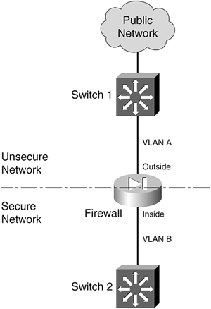
In some environments, the use of separate switches on each side of a firewall might be too expensive. A single switch can carry multiple VLANs, each logically isolated from the others. Why not connect several of a firewall's interfaces to just one switch, each interface assigned to a different VLAN? Along the same lines, a firewall could connect to a switch using only a single physical interface. Each logical interface could be carried over that interface as a trunk, where the VLANs are naturally isolated in the switch, as illustrated in Figure 3-4. Figure 3-4. Using a Single Switch to Support a Firewall 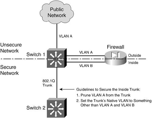
You can use a single switch to support multiple firewall interfaces. The inherent VLAN isolation works well with the inherent security isolation. However, you should carefully consider a few issues if you decide to connect a firewall in this fashion. First, you should always be sure to prune any unused VLANs from trunk links that connect the firewall/switch combination to other networks. The basic idea is that no VLAN is allowed to extend from the outside, unsecure network into the inside, secure network without passing through the firewall first. If a VLAN does extend on in, there will always be the possibility that it can be exploited for a malicious attack or a compromise. In Figure 3-4, VLAN A carries traffic to the firewall's outside interface. VLAN A should be pruned from the trunk link between Switch 1 and Switch 2 so that it is contained outside the secure internal network. Securing Trunk Links Connected to Firewalls Another thing to consider is the potential for an exploit called VLAN hopping. When a VLAN on the public side of a boundary switch extends on into the internal side as a trunk's native VLAN, it can be used to carry unexpected traffic that can "hop" over to a different VLAN. This can occur even if the native VLAN is not intended to carry any traffic into the inside network. VLAN hopping occurs when someone can send packets on the outside VLAN as if they are encapsulated for an 802.1Q trunk. The boundary switch accepts the packets and then forwards them on the native VLAN of the inside trunk. Now, the spoofed encapsulation becomes relevant, causing other inside switches to unencapsulate the packets and send the malicious contents onto other secured VLANs. In effect, an outside user can inject packets onto VLANs that aren't even visible or accessible on the outside. Consider the network shown in Figure 3-5, where a firewall separates inside and outside networks but both networks pass through the same switch. VLAN 100 is the only VLAN allowed to extend to the outside public network. Switch 1, at the network's secure boundary, brings the inside network in over an 802.1Q trunk link. A trunk link is used because the firewall might be configured to use additional logical interfaces in the future, and those VLANs can be carried over the trunk as well. Figure 3-5. Example of a VLAN Hopping Exploit 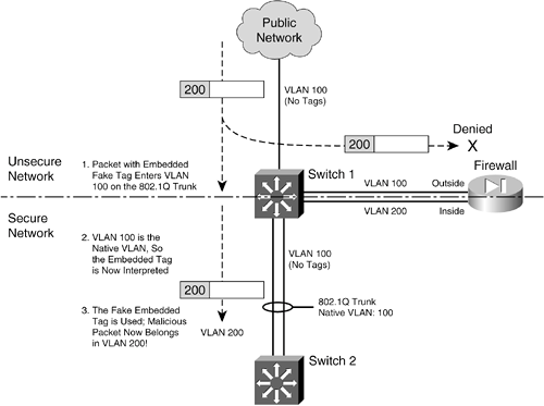
The trunk link has been configured with VLAN 100 as its native VLAN. This might have been done as an oversight, with the assumption that no other switch or host would ever connect to VLAN 100 on the inside network. However, that native VLAN is used as the springboard to get inside the secure network. A malicious user on the outside (VLAN 100) sends a packet toward the inside. The packet is carefully crafted such that it contains an 802.1Q VLAN tag for VLAN 200even though it is being sent over a nontrunking link that supports only a single VLAN. If the packet is a broadcast, it might be sent toward the firewall's outside interface (also on VLAN 100) when it reaches Switch 1. The firewall examines the packet and denies it entry into the inside network, as expected. Most likely, the packet is sent as a unicast destined for an address on the internal network. When the packet reaches Switch 1, a curious thing happens. The packet originated on VLAN 100, so the switch can forward it onto VLAN 100 of the 802.1Q trunk link. VLAN 100 is the trunk's native VLAN, so the switch transmits the packet without adding its own VLAN tag. Now when the packet appears on the trunk link, the embedded fake tag is interpreted as an actual 802.1Q tag! Downstream switches forward the packet based on its newly exposed VLAN 200 tag. Suddenly, the packet has "hopped" from VLAN 100 on the outside to VLAN 200 on the inside network. To thwart VLAN hopping, you should always carefully configure trunk links so that the native VLANs are never used to carry legitimate traffic. In other words, set a trunk's native VLAN to an unused VLAN. In Figure 3-4, the native VLAN of the inside trunk should be set to an unused VLAN other than VLAN A, which is present on the outside, and other than VLAN B, which is present on the inside. Trunks on opposite sides of a boundary switch should have different unused native VLANs so that the native VLAN of one side doesn't pass through to the native VLAN of the other side. Figure 3-6 shows this scenario. Notice that the native VLANs on the inside and outside are set to different but unused VLAN numbers. Figure 3-6. Securing Trunk Links on a Firewall Boundary Switch 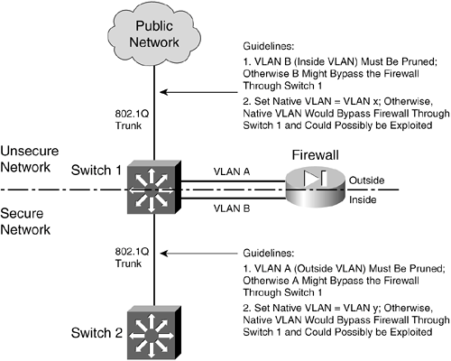
CAUTION Whenever possible, you should keep the trusted and untrusted networks physically separate, carried over separate switches. Don't depend on the logical separation of VLANs within a single switch to provide inherent security. There is always a risk of misconfiguration or of an exploit that would allow untrusted traffic to enter the trusted network.
Bypass Links One last thing you should consider is the use of links to bypass a firewall. It might seem odd to secure a network with a firewall, only to open a path for traffic to go around it. Some environments must still connect other non-IP protocols between inside and outside networks, simply because a firewall can inspect only IP traffic. Still others might bypass IP multicast traffic to keep the firewall configuration simple. The idea behind a bypass path is that any traffic using the path is either isolated from or incompatible with traffic passing through the firewall. In fact, you might pass some IP traffic around a firewall on a VLAN that never connects to another inside network. You might support something like a wireless LAN in your network, carried over the same switches as your secured VLANs, but where wireless users are considered "outsiders." Then, you might pass a wireless VLAN around the firewall, with the intention that it connects only to networks outside the firewall. Figure 3-7 shows a basic network that allows some traffic to bypass a firewall. In the left portion of the figure, IP traffic passes through the firewall while Novell IPX traffic passes around it over VLAN C. This is allowed only because some users on the outside map drives on IPX file servers on the inside. Figure 3-7. Example of Risk When Bypassing a Firewall 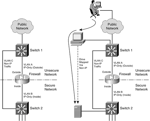
TIP At the very least, you should configure very strict IPX access lists on the Layer 3 switches at each end of the VLAN C link. If IPX traffic must be bypassed around the firewall, it should still be governed by whatever means you have available. You should also consider using a transparent (Layer 2) firewall to handle the traffic that would otherwise flow over a link bypassing a Layer 3 firewall. For non-IP protocols, a transparent firewall can filter only according to EtherType values. However, no stateful inspection of protocols such as IPX is possible.
From a routing standpoint, IP and IPX are "ships in the night," coexisting on switches but not intermingling. However, consider the right portion of Figure 3-7. An outside user has managed to compromise a PC that is also on the outside. This PC has a drive mapped over IPX to a secure file server. Without passing through the firewall, the outside user has managed to gain access to data on a "secure" server on the internal network. The solution here is to be very critical of bypassing any sort of traffic around a firewall. Even if you think you've thought of every possible angle to keep internal resources isolated, there still might be a way for someone to gain access. |