12-3. Switched Port Analyzer Switched Port Analyzer (SPAN) mirrors traffic from one or more source switch ports or a source VLAN to a destination port. This allows a monitoring device such as a network analyzer to be attached to the destination port for capturing traffic. SPAN source and destination ports must reside on the same physical switch. Multiple SPAN sessions can be configured to provide several simultaneous monitors. Remote SPAN (RSPAN) provides traffic mirroring from a source on one switch to a destination on one or more remote switches. RSPAN is carried from source to destination over a special RSPAN VLAN. RSPAN is only available on the Catalyst 4000 and 6000 switch families.
NOTE What happens if a speed mismatch occurs between the SPAN source and destination ports? During a SPAN session, a switch merely copies the packets from the source and places them into the output queue of the destination port. If the destination port becomes congested, the SPAN packets are dropped from the queue and are not seen at the destination. Traffic from the SPAN source then is not affected by any congestion at the SPAN destination.
SPAN Configuration 1. | Create a SPAN session.
- (COS and IOS Catalyst 2900/3500 only) Select the source and destination: COS | [View full width] set span src-mod/src-ports | src-vlans | sc0}  {dest-mod/dest-port} [rx | tx | both] [inpkts {enable | disable}] [learning {enable | disable}] [multicast {enable | disable}] [filter vlans...] [create] {dest-mod/dest-port} [rx | tx | both] [inpkts {enable | disable}] [learning {enable | disable}] [multicast {enable | disable}] [filter vlans...] [create]
| IOS | [View full width] (global) interface dest-interface (interface) port monitor [src-interface |)vlan src-vlan]
|
The source of traffic for the SPAN session can be either switch ports, VLANs, or the switch management interface (COS only). If switch ports are to be monitored, they are identified as src-mod/src-ports (COS; can be one or a range of ports) or as src-interface (IOS; only a single interface type and number).
If VLANs are to be monitored, they are identified as src-vlans (COS allows one or a range of VLAN numbers; IOS allows only a single VLAN number). COS switches also allow the sc0 management interface to be used as a source if desired.
The SPAN destination port, where the monitoring device is connected, is identified as dest-mod/dest-port (COS). For IOS switches, the destination interface is selected by the interface dest-interface command before the port monitor command is applied. On IOS switches, the destination port must belong to the same VLAN as the source.
The direction of source traffic to be monitored can also be selected, as rx (traffic received at the source), tx (traffic transmitted from the source), or both (default). IOS switches inherently monitor traffic in both directions.
By default multicast traffic is monitored as it exits from the source. To disable this behavior, use the multicast enable keywords.
The destination port is normally used for a traffic-capturing device, so inbound traffic on the destination port is not allowed by default. If needed, you can enable normal switching of inbound traffic at the destination with the inpkts enable keywords.
CAUTION Remember that the destination port always belongs to an active VLAN, whether it is monitoring for a SPAN session or not. As well, a SPAN destination port does not run the STP so that STP bridge protocol data units (BPDUs) can be monitored. Therefore, if inpkts is enabled and the destination port is connected to another network device, a spanning-tree loop can easily be formed. By default the MAC addresses from inbound packets on the destination port are learned, as they are on any switch port. You can disable address learning on the destination with the learning disable keywords.
If a trunk is being used as a source port, you can filter out specific VLANs to be monitored. On a COS switch, use the filter vlans (one or a range of VLAN numbers) keywords. An IOS switch has no SPAN option to do this. However, you can assign the destination port to the same VLAN you want to monitor in the trunk source.
TIP If you are monitoring sources that belong to several VLANs, you might want to have a record of the source VLANs for the packets appearing on the destination port. To do this, enable trunking on the destination port. The source packets are tagged with the VLAN numbers from which they originated. TIP COS switches allow more than one active SPAN session. You can configure the first session as shown in the full syntax for the set span COS command. To create subsequent sessions, use the create keyword. If create is omitted, the newly configured session overwrites the first session. - (IOS; Catalyst 6000 only) Select the source and destination. - Select the session source: COS | N/A | IOS | [View full width] (global) monitor session session {source {interface interface} | {vlan vlan-id}} [, | - | rx | tx | both]
|
The SPAN session is uniquely identified by session (1 or 2). The source can be an interface (an interface type and number or a port-channel number) or a VLAN number vlan-id (1 to 1005). Multiple source VLANs can be given by using the vlan keyword followed by vlan-id numbers separated by commas (,). To specify a range of VLAN numbers, use the vlan keyword followed by the first and last vlan-id numbers, separated by a dash (-). - Source traffic to be monitored can be one of rx (traffic received at the source), tx (traffic transmitted from the source), or both (the default). - Select the session destination: COS | N/A | IOS | [View full width] (global) monitor session session {destination {interface interface} [, | -] | {vlan vlan-id}}
|
The destination for the SPAN session (session number 1 or 2) can be an interface (interface type and number) or a VLAN number vlan-id (1 to 1005). Multiple destinations can also be specified, if needed. These can be given with the interface keyword, followed by a list of interface numbers separated by commas (,). To specify a range of interfaces, use the interface keyword followed by the first and last interface numbers, separated by a dash (-). - (Optional) Filter VLANs on a trunk source: COS | N/A | IOS | [View full width] (global) monitor session session filter vlan vlan-id} [, | -]
|
If a trunk is being used as a source port, you can filter the trunk to select specific VLANs to be monitored. A VLAN number is identified as vlan-id (1 to 1005). Multiple source VLANs can be given with the vlan keyword, followed by a list of vlan-id numbers separated by commas (,). To specify a range of VLANs, use the vlan keyword followed by the first and last vlan-id numbers, separated by a dash (-).
| 2. | (Optional) Disable a SPAN session:
COS | set span disable [dest-mod/dest-port | all]
| IOS | (global) no monitor session session
-OR- (interface) no port monitor
|
SPAN sessions can be disabled individually, referenced by their destination dest-mod/dest-port (COS) or by session number (IOS). For Catalyst 2900/3500 IOS switches, SPAN sessions are disabled on the destination interfaces with the no port monitor command.
|
RSPAN Configuration 1. | Create one or more VLANs to be used by RSPAN:
COS | set vlan vlan-id rspan
| IOS | N/A |
The VLAN number vlan-id (1 to 1000, 1025 to 4094) should be created on all switches from the RSPAN source to the RSPAN destination. As well, the RSPAN VLAN should be trunked end-to-end, because it carries the remotely monitored traffic. Create a different RSPAN VLAN for each RSPAN session that you will be using. See Chapter 6, "VLANs and Trunking," for more configuration information related to VLANs and VTP.
NOTE Notice the use of the rspan keyword when the RSPAN VLAN is created. This must be used so that the VLAN can correctly carry the RSPAN traffic. An RSPAN-capable switch floods the RSPAN packets out all of its ports belonging to the RSPAN VLAN, in an effort to send them toward the RSPAN destination. This is because a switch participating in RSPAN has no idea where the destination is located. Otherwise, if the switch were using a regular VLAN, it would try to forward the RSPAN packets on ports where the packet destination addresses were detectedsomething quite different from RSPAN altogether! This is why all switches involved in the end-to-end RSPAN path must be RSPAN-capable. Currently, this is limited to the Catalyst 4000 and 6000 families.
TIP Create and maintain the RSPAN VLAN for the special monitoring purpose. Don't allow any normal hosts to join the RSPAN VLAN. Ideally, all the switches will belong to a common VTP domain so that the VLAN can be created on a VTP server and propagated to all other switches. VTP pruning also prunes the RSPAN VLAN from unnecessary trunks, limiting the traffic impact in unrelated areas of the network. Be aware that RSPAN traffic can increase the traffic load on a trunk, even though RSPAN is restricted to one special VLAN in the trunk. If the additional load is significant, the normal and monitored traffic contends with each other for available bandwidth and both could suffer. | 2. | (Source switches only) Select the monitor sources:
COS | [View full width] set rspan source {src-mod/src-ports... | vlans... | sc0} {rspan-vlan} [rx | tx | both] [multicast {enable | disable}] [filter vlans...] [create]
| IOS | N/A |
The RSPAN source is identified as one or more physical switch ports src-mod/src-ports, as one or more VLAN numbers vlans, or as the management port sc0. This is performed only on the switch where the source is connected. The RSPAN VLAN number to be used is rspan-vlan (1 to 1000, 1025 to 4094). The direction of the monitored traffic can be rx (traffic received at the source), tx (traffic transmitted from the source), or both (the default).
By default multicast traffic is monitored as it exits from the source. To disable this behavior, use the multicast disable keywords.
If a trunk is being used as a source port, you can filter the trunk to select specific VLANs to be monitored by using the filter vlans (one or a range of VLAN numbers) keywords.
TIP You can configure more than one active RSPAN session at the source switch. The first session is created as shown above. To create subsequent sessions, use the create keyword. If create is omitted, the newly configured session overwrites the first session. You should use a different RSPAN VLAN for each session. | 3. | (Destination switches only) Select the destinations:
COS | [View full width] set rspan destination mod/port {rspan-vlan} [inpkts {enable | disable}] [learning {enable | disable}] [create]
| IOS | N/A |
The RSPAN destination port, where the monitoring device is connected, is identified as mod/port. This is performed only on the switch where the destination port resides.
The destination port is normally used for a traffic-capturing device, so inbound traffic on the destination port is not allowed by default. If needed, you can enable normal switching of inbound traffic at the destination with the inpkts enable keywords.
NOTE RSPAN differs from SPAN in that the destination port always has the STP enabled. This prevents bridging loops from accidentally forming if other network devices are connected to the destination port. However, this also means that you can't monitor STP BPDUs with RSPAN. By default the MAC addresses from inbound packets on the destination port are learned, as they are on any switch port. You can disable address learning on the destination with the learning disable keywords.
TIP You can also configure more than one active RSPAN session at the destination switch. The first session is created as shown previously. To create subsequent sessions, use the create keyword. If create is omitted, the newly configured session overwrites the first session. You should use a different RSPAN VLAN for each session. | 4. | (Intermediate switches only) No further configuration is needed.
The switches in the path from RSPAN source to destination do not need to know about any specific RSPAN configuration. After all the RSPAN VLANs have been created end-to-end, the intermediate switches flood the RSPAN traffic correctly toward the destinations. Remember that all the intermediate switches must be RSPAN-capable.
| 5. | (Optional) Disable an RSPAN session:
COS | set rspan disable source [rspan-vlan | all]
-OR- set rpsan disable destination [mod/port | all]
| IOS | N/A |
You can disable an RSPAN session when it is no longer needed. Source sessions are identified by the rspan-vlan (VLAN number) or the all keyword. Destination sessions are identified by the destination port as mod/port or the all keyword.
|
SPAN Examples Network analyzer A (a "sniffer") is connected to a Catalyst switch port 5/1 and will monitor all traffic on VLAN 58. A PC is connected to port 4/39 and a file server to port 2/4 of a Catalyst switch. Network analyzer B is connected to port 5/48. The switch is configured for a SPAN session that will allow the analyzer to capture all traffic to and from the server. Figure 12-1 shows a network diagram of the two SPAN sessions. Figure 12-1. Network Diagram for the SPAN Example 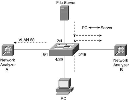
COS | set span 58 5/1 both set span 2/4 5/48 both create
| IOS | (global) interface fast 5/1 (interface) port monitor vlan 58 (global) interface fast 5/48 (interface) port monitor fast 2/4
| IOS 6000 | [View full width] (global) monitor session 1 source vlan 58 both (global) monitor session 1 destination interface fast 5/1 (global) monitor session 2 source interface fast 5 /48 both (global) monitor session 2 destination interface fast 2/4
|
Figure 12-2 shows a network of three switches. A file server is connected to Catalyst B port 3/1. A network analyzer is connected to Catalyst C port 5/48. Catalyst A connects Catalysts B and C by two trunk ports. RSPAN VLAN 901 carries all the RSPAN traffic from the source to the destination. (Assume for this example that Catalyst B is the VTP server for the domain of three switches.) Figure 12-2. Network Diagram for the RSPAN Example 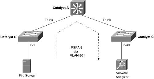
The configuration needed for Catalyst B follows: COS | set vlan 901 rspan set rspan source 3/1 901 both
| IOS | N/A |
The configuration needed for Catalyst C follows: COS | set rspan destination 5/48 901
| IOS | N/A |
No additional configuration is needed for Catalyst A because it merely transports RSPAN traffic over the RSPAN VLAN 901. Displaying Information About SPAN Table 12-4 lists some switch commands that you can use to display helpful information about SPAN. Table 12-4. Switch Commands to Display SPAN InformationDisplay Function | Switch OS | Command |
|---|
SPAN session activity | COS | show span
| IOS | show monitor [session session-number]
-OR- show port monitor
| RSPAN session activity | COS | show rspan | IOS | N/A |
COS switches display the sourceports with "Admin Source" and "Oper Source" labels. All VLANs or ports that are configured as sources are listed as administrative sources. However, only the ports that are being actively monitored (not disabled) are listed as operational sources. |