7-2. STP Configuration 1. | (Optional) Enable or disable STP:
COS | set spantree [enable | disable] [vlan]
| IOS | (global) [no] spanning-tree [vlan vlan]
|
STP is enabled by default on VLAN 1 and any newly created VLANs. Without a specified VLAN, STP is enabled or disabled on all VLANs. Be aware that if STP is disabled, bridging loops are not detected and prevented. You should always enable STP.
| 2. | (Optional) Set the STP mode for the switch (Catalyst 4000 and 6000 only):
COS | set spantree mode {mistp | pvst+ | mistp-pvst+ | mst}
| IOS | N/A |
By default, all Catalyst switches run PVST+ STP for one instance of STP on each VLAN. To configure other STP modes, use the keywords mistp (MISTP), mistp-pvst+ (MISTP-PVST+ interoperability), or mst (MST).
| 3. | (MST only) Activate an MST instance (Catalyst 4000 and 6000 only).
- a. Identify the MST region:
COS | set spantree mst config {name name} {revision number}
| IOS | N/A |
The MST region is identified by name (a text string up to 32 characters). If no name is given, no region name is used. You can use a region revision number to indicate the number of times the region configuration has changed. The revision number (0 to 65535, default 1) must be explicitly set and is not automatically incremented with region changes.
- b. Map one or more VLANs to the instance:
COS | set spantree mst instance vlan vlan
| IOS | N/A |
A vlan number (1 to 1005, 1025 to 4094) is mapped to the MST instance (0 to 15). This mapping is held in the MST region buffer until the changes are committed.
- c. Commit the region mapping:
COS | set spantree mst config commit
| IOS | N/A |
MST region configuration changes are placed into an edit buffer, which is locked to the user making the change. These changes must be committed before they will become active. Committing the changes also unlocks the edit buffer so that another edit session can be initiated.
- d. (Optional) Undo the last region configuration changes:
COS | set spantree mst config rollback [force]
| IOS | N/A |
If MST region configuration changes have been made in error, they can be retracted by using the rollback keyword. This can be done only on changes that have not yet been committed or applied. If another user has made changes and holds the edit buffer lock, you can add the force keyword to unlock the buffer and remove the changes.
| 4. | (Optional) Placement of the root bridge switch.
NOTE The root bridge (and secondary root bridges) should be placed near the "center" of the network, so that an optimum spanning-tree topology is computed. Typically, the root is located in the core or distribution layers of the network. If you choose not to manually configure the root placement, the switch with the lowest BID will win the root election. This almost always produces a spanning-tree topology that is inefficient. COS | [View full width] PVST+: set spantree root [secondary] [vlans] [dia  net-diameter] [hello hello-time] MISTP: set spantree root [secondary] mistp-instance instance [dia net-diameter] [hello hello-time] MST: set spantree root [secondary] mst instance [dia net-diameter] [hello hello-time] net-diameter] [hello hello-time] MISTP: set spantree root [secondary] mistp-instance instance [dia net-diameter] [hello hello-time] MST: set spantree root [secondary] mst instance [dia net-diameter] [hello hello-time]
| IOS | [View full width] PVST+: (global) spanning-tree vlan vlan root {primary | secondary} [diameter net-diameter [hello-time hello-time]]
|
The switch is made to become the primary root bridge for the VLANs (a list of VLAN numbers 1 to 1005 and 1025 to 4094) or STP instances (1 to 16) specified (VLAN 1 if unspecified). The bridge priority value is modified as follows: If it is more than 8192, it is set to 8192; if it is already less than 8192, it is set to a value less than the current root bridge's priority. You can use the secondary keyword to place a secondary or backup root bridge, in case of a primary root failure. Here, the bridge priority is set to 16384. (For MST, the root priority is set to 24576, and the secondary priority to 28672.)
The dia keyword specifies the diameter or the maximum number of bridges or switches between two endpoints across the network (1 to 7, default 7). The BPDU Hello Time interval can also be set (default 2 seconds). Setting the network diameter causes other STP timer values to be automatically calculated and changed. You can adjust the timers explicitly with other commands, but adjusting the diameter hides the complexity of the timer calculations.
NOTE This Supervisor IOS command is not available on the Catalyst 2900XL and 3500XL family switches. | 5. | (Optional) Adjust the bridge priority:
COS | [View full width] PVST+: set spantree priority priority vlans MISTP: set spantree priority priority mistp-instance instance-list MST: set spantree priority priority mst instance-list
| IOS | [View full width] PVST+: (global) spanning-tree vlan vlan priority priority
|
You can also directly modify the bridge priority to achieve other values than the automatic root or secondary priorities. The priority can be set on a per-VLAN or -instance basis. Instances can be given as an instance-list, as one or more instance numbers separated by commas, or a hyphenated range of numbers.
To force a switch to become the root, the priority should be chosen such that the root bridge has a lower priority than all other switches on that VLAN or STP instance. The bridge priority ranges from 0 to 65535 (default 32768) for PVST+, or one of the values 0 (highest), 4096, 8192, 12288, 16384, 20480, 24576, 28672, 32768, 36864, 40960, 45056, 49152, 53248, 57344, and 61440 (lowest) for MISTP.
| 6. | (Optional) Prevent other switches from becoming the STP root bridge:
COS | set spantree guard {root | none} mod/port
| IOS | (interface) spanning-tree guard {root | none}
-OR- (interface) spanning-tree rootguard
|
STP Root Guard will be enabled on the port or interface. If another bridge connected to that port tries to become the root, the port will be moved to root-inconsistent (listening) STP state. When BPDUs are no longer detected on the port, it will be moved back into normal operation.
On Catalyst 2900XL and 3500XL family switches, the rootguard keyword is used.
| 7. | (Optional) Tune the root path cost.
- a. (Optional) Set the port cost scale (Catalyst 4000 and 6000 only):
COS | set spantree defaultcostmode {short | long}
| IOS | [View full width] (global) spanning-tree pathcost defaultcost-method {long | short}
|
By default, PVST+ switches use the short (16-bit) port cost values. If you have any ports that are 10 gbps or greater, you should set the port cost scale to long (32-bit) values on every switch in your network. MISTP, MISTP-PVST+, and MST modes use long mode by default.
- b. Set the port cost for all VLANs or instances:
COS | set spantree portcost mod/port cost [mst]
| IOS | (interface) spanning-tree cost cost
|
The port cost can be set to cost (1 to 65535 short or MISTP mode, 1 to 2000000 long mode) for all VLANs or STP instances. The mst keyword signifies a port used in MST.
- c. Set the port cost per VLAN or per instance:
COS | [View full width] PVST+: set spantree portvlancost mod/port [cost cost] [vlan-list] MISTP: set spantree portinstancecost mod/port [cost cost] [instances] MST: set spantree portinstancecost mod/port [cost cost] mst [instances]
| IOS | [View full width] PVST+: (interface) spanning-tree vlan vlan-id cost cost
|
The port cost can be set to cost (1 to 65535 short mode, 1 to 2000000 long mode) for the VLAN vlan-id or the list of VLANs, vlan-list, or STP instance (0 to 15).
| 8. | (Optional) Tune the port priority.
- a. Set the port priority for all VLANs or instances:
COS | set spantree portpri mod/port priority [mst]
| IOS | (interface) spanning-tree port-priority port-priority
|
The port priority can be set to priority (0 to 63 for COS, or 2 to 255 for IOS). Use the mst keyword to signify that the port is used for MST.
- b. Set the port priority per VLAN or per instance:
COS | [View full width] PVST+: set spantree portvlanpri mod/port priority [vlans] MISTP: set spantree portinstancepri mod/port priority [instances] MST: set spantree portinstancepri mod/port priority mst [instances]
| IOS | [View full width] PVST+: (interface) spanning-tree vlan vlan-list port-priority priority
|
The port priority can be set to priority (0 to 63 for COS, 0 to 255 for IOS) for the VLAN vlan-id or the list of VLANs, vlan-list, or STP instance (0 to 15).
| 9. | (MISTP only) Activate a MISTP instance.
- a. Enable a MISTP instance:
COS | set spantree enable mistp-instance {instance | all}
| IOS | N/A |
MISTP instance 1 is enabled by default. You can enable other instances by instance number (1 to 16) or the keyword all.
- b. Map VLANs to a MISTP instance:
COS | set vlan vlan-list mistp-instance {instance | none}
| IOS | N/A |
One or more VLAN numbers can be given as vlan-list, to be mapped to a single MISTP instance. If you happen to assign a VLAN to more than one instance, all of that VLAN's ports will be set to STP blocking mode. You can use the keyword none to unmap the VLANs from any mapped instance.
| 10. | (Optional) Detect unidirectional connections with UDLD.
- a. Enable UDLD on the switch:
COS | set udld {enable | disable}
| IOS | (global) udld {enable | aggressive}
|
By default, UDLD is disabled. It must be enabled before it can be used on specific ports. The Supervisor IOS allows the keyword aggressive to be used to globally enable UDLD aggressive mode on all Ethernet fiber-optic interfaces.
- b. (Optional) Adjust the UDLD message interval timer:
COS | set udld interval interval
| IOS | (global) udld message time interval
|
The UDLD message interval can be set to interval (7 to 90 seconds; COS default is 15 seconds, Supervisor IOS is 60 seconds).
- c. Enable UDLD on specific ports:
COS | set udld {enable | disable} mod/port
| IOS | (interface) udld {enable | disable}
|
After UDLD has been globally enabled on a switch, UDLD is also enabled by default on all Ethernet fiber-optic ports. UDLD is disabled by default on all Ethernet twisted-pair media ports.
- d. (Optional) Enable UDLD aggressive mode on specific ports:
COS | set udld aggressive-mode enable | disable mod/port
| IOS | (interface) udld aggressive
|
After aggressive mode has been enabled on a port, the port is disabled when a unidirectional connection is detected. It must be manually reenabled after the problem has been corrected. On the Supervisor IOS, use the EXEC command udld reset to reenable all ports that are disabled by UDLD.
| 11. | (Optional) Improve STP stability with Loop Guard:
COS | set spantree guard loop mod/port
| IOS | N/A |
Loop Guard should be enabled only on the ports that you know are root or alternate root ports. For example, the uplink ports on an access layer switch would always be root or alternate root ports, because they are closest to the root bridge. (This assumes that you have placed the root bridge toward the center of your network.)
|
Displaying Information About STP Table 7-2 lists the switch commands that you can use to display helpful information about STP. Table 7-2. Switch Commands to Display STP InformationDisplay Function | Switch OS | Command |
|---|
STP for a specific VLAN | COS | show spantree vlan active
| IOS | (exec) show spanning-tree vlan vlan
| STP state for all VLANs on a trunk | COS | show spantree mod/num
| IOS | (exec) show spanning-tree interface mod/num
| STP statistics for a VLAN on a port | COS | show spantree statistics mod/num vlan
| IOS | N/A | Ports in the blocking state | COS | show spantree blockedports [vlan]
| IOS | N/A | Log STP events | COS | set logging level spantree severity
| IOS | N/A |
STP Configuration Examples As a good practice, you should always configure one switch in your network as a primary root bridge for a VLAN and another switch as a secondary root. Suppose you build a network and forget to do this. What might happen if the switches are left to sort out a spanning-tree topology on their own, based on the default STP parameters? Poor STP Root Placement The top half of Figure 7-2 shows an example network of three Catalyst switches connected in a triangle fashion. Catalysts C1 and C2 form the core layer of the network, whereas Catalyst A connects to the end users in the access layer. (C1 and C2 might also be considered distribution layer switches if the overall campus network doesn't have a distinct core layer. In any event, think of them as the highest layer or the backbone of the network.) Figure 7-2. Network Diagram Demonstrating Poor STP Root Placement 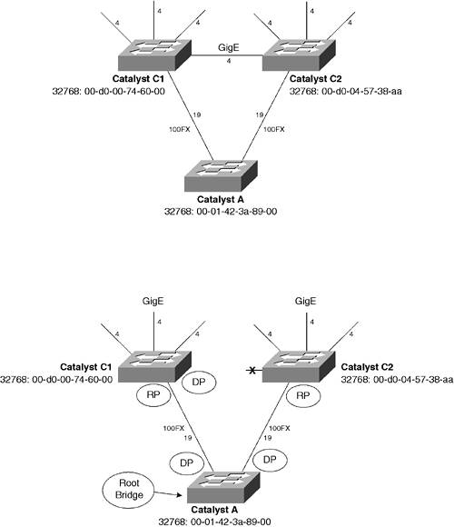
As it might be expected, the links between the core and other switches are Gigabit Ethernet. The uplinks from Catalyst A into the core, however, are Fast Ethernet. When the root bridge is elected, Catalyst A wins based on its lower MAC address. (All switches have their default bridge priorities of 32768.) Both of the uplink ports on switch A become designated ports, because it is now the root. The downlinks from C1 and C2 to switch A become root ports. Switch C1 makes its Gigabit Ethernet link to C2 a designated port because it has the lower sending BID. And sadly, switch C2 must move its Gigabit Ethernet link to C1 into the blocking state because it is neither a root nor a designated port. You can see this in the lower half of the figure. Clearly, an inefficient topology has surfaced, because all the traffic passing across the network core must now pass across lower-speed links through switch A. Switch A, being an access layer switch, is also likely to have less horsepower than the core layer switches. To remedy this situation, place the STP root bridge somewhere in the core or highest hierarchical layer of the network. You can do this with the following command for VLAN 10 on switch C1, for example: COS | set spantree root 10
| IOS | (global) spanning-tree vlan 10 root primary
|
Alternatively, you can explicitly set the bridge priorities with these commands (available on all Catalyst models): COS | set spantree priority 8192 10
| IOS | (global) spanning-tree vlan 10 priority 8192
|
STP Load Balancing Figure 7-3 shows a network diagram consisting of three switches that are connected in a triangle fashion. Each of the links between switches is a trunk, carrying two VLANs. The switches will be configured so that the two VLANs are load balanced across the available trunks. The lower half of the figure shows the resulting spanning-tree topologies for VLAN 100 and VLAN 101. Figure 7-3. Network Diagram for the STP Load-Balancing Example 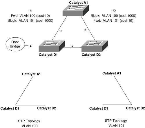
Distribution switch Catalyst D1 will be chosen as the root bridge. Some users connected to access switch Catalyst A1 are on VLAN 100, whereas other users are on VLAN 101. The idea is to have VLAN 100 traffic forwarded to distribution switch Catalyst D1, while VLAN 101 traffic goes to Catalyst D2. NOTE Switch D1 has been selected as the root bridge for both VLANs for simplicity and to demonstrate the use of port cost adjustments in load balancing. You could also configure D1 as the root for VLAN 100 and D2 as the root for VLAN 101. The resulting STP topologies would be the same, but there would be no need to adjust the port costs in switch A1.
An additional benefit is that the two trunk links will failover to each other. Should one trunk link fail, the other moves from blocking into forwarding mode, forwarding both VLANs 100 and 101 across the same trunk. If the STP UplinkFast feature is also used on both switches, the link failover is almost instantaneous. Switch Catalyst D1 will be configured as the primary root bridge for both VLANs, whereas Catalyst D2 will become the secondary root bridge. If D1 fails, D2 becomes the new root. Catalyst D1 can be configured with these commands (if they are available on the switch OS): COS | set spantree root 100,101
| IOS | (global) spanning-tree vlan 100 root primary (global) spanning-tree vlan 101 root primary
|
Alternatively, you can explicitly set the bridge priorities with these commands (available on all Catalyst models): COS | set spantree priority 8192 100 set spantree priority 8192 101
| IOS | (global) spanning-tree vlan 100 priority 8192 (global) spanning-tree vlan 101 priority 8192
|
Catalyst D2 can be configured with these commands to become the secondary root: COS | set spantree root secondary 100,101
| IOS | (global) spanning-tree vlan 100 root secondary (global) spanning-tree vlan 101 root secondary
|
Alternatively, you can explicitly set D2's bridge priorities: COS | set spantree priority 8200 100 set spantree priority 8200 101
| IOS | (global) spanning-tree vlan 100 priority 8200 (global) spanning-tree vlan 101 priority 8200
|
Finally, Catalyst A1 will have the port cost adjusted for ports 1/1 and 1/2 for the two VLANs. Recall that the default port cost is shown as 19 in the diagram. We will be setting the new costs to 1000 on the undesirable paths so that those ports will be blocking. For example, VLAN 101 on port 1/1 will be blocked because it has a higher port cost of 1000: COS | set spantree portvlancost 1/1 cost 1000 101 set spantree portvlancost 1/2 cost 1000 100
| IOS | (global) interface fastethernet 1/1 (interface) spanning-tree vlan 101 cost 1000 (global) interface fastethernet 1/2 (interface) spanning-tree vlan 100 cost 1000
|
|