| Audio filters are effects (reverb and echo), equalizations (EQ), compression and expansion, or noise reduction applied to entire audio clips or portions of audio clips. They are used to enhance a clip's sound quality to add some punch to the telling of your story. Or they can be used to correct errors made in the recording process. To add filters, highlight the audio clip from the sequence in the Timeline window, and select a filter from the Effects menu, as shown in Figures 8.1 and 8.2. You can also drag from the list in the Browser's Effects tab and drop one or more filters by Ctrl-clicking your choices. You can drag this set of filters to the Viewer, or you can drag them to the clip or set of clips you want to add them to in the Timeline that contains the sequence you are working with (see Figures 8.3 and 8.4). Alternatively, you can highlight an audio clip in the Timeline window and double-click an audio filter's icon from the Effects tab of the Browser window. This filter is added to the clip as it plays back in the sequence. Figure 8.1. The Apple Audio Effects menu. 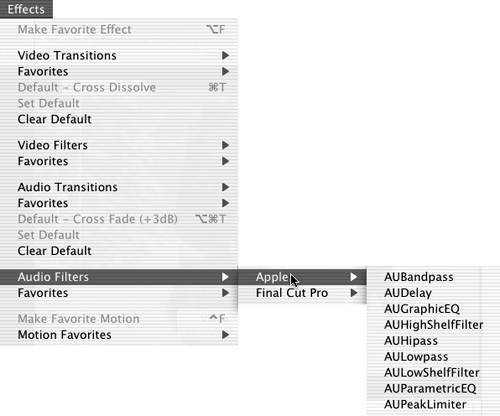 Figure 8.2. The Final Cut Pro Audio Effects menu. 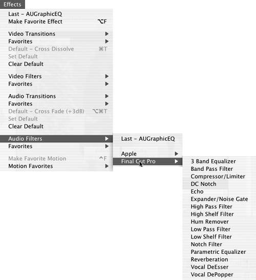 Figure 8.3. Dragging an audio effect from the Browser to the Viewer.  Figure 8.4. Dragging an audio effect from the Browser to the Timeline.  The Filters tab is shown in Figure 8.5. It contains filters and their controls after they are applied to a clip from either the Browser's Effects tab or the Filters menu. You can add a whole range of filters to audio clips. You are not limited to just one. You can add as many as you want, including the same one more than once, but keep in mind that Final Cut Pro addresses them in the order you have added them, which might affect the way they sound in concert with each other. Figure 8.5. The Filters tab in the Viewer window.  To change their order, it's simply a matter of clicking their names and rearranging them by dragging them up or down the list. If you apply a filter to a stereo pair, all filters you add to the pair are applied equally if linked selection is on. In the case of Audio 1 and 2 clips, if linked selection is not active when you apply an audio filter, it is applied to only the selected track, or the track you drag it to. This becomes important if you are working with audio that was recorded with one actor to one track and another actor to another track, or a set of two different microphones on the same subject. You might need to enhance one track, but not the other, or apply different filters to each track. tip Keep in mind that a filter's effect is applied to the entire clip. To limit this condition without keyframing its entrance and exit, you can use the Range Selection tool to select just the portion of the audio clip in the Timeline window you want to affect. You can also use the Razor Blade tool to "slice" a clip into sections. For example, you might need to limit an effect to the center section of a given audio clip. If you add an edit point with the Razor Blade tool before and after the section you want to affect, you apply the effect to this new section only, not to the entire clip. Both techniques can also be used to save some rendering time. You also save the disk space that would be used for an entire clip's render file. Alternatively, if you open the Viewer to display the keyframe display areas next to the various parameter adjustments in a filter's controls, to the right of the filter's name is a band with two black vertical lines. These lines indicate the part of the clip being used in the sequence. You can drag them to minimize the duration of the filter's effect. What's more, each filter you apply to a clip can have a different duration, because each filter has its own set of trimming lines. You might want to add an EQ filter to begin at the head of a clip and then start a reverb filter later as a character walks into a tunnel, for example. This same technique can be used with video filters. In effect, you can have one clip with many filters and control just when these filters make their entrances and exits.
A Second Place to Adjust Audio Filters New to FCP 4, there are two different areas you can access to adjust the filters after they are appliedthe Viewer's Filters tab and the keyframing area of the Timeline window (see Figure 8.6). To pull up the context menu shown in Figure 8.7, you Ctrl-click beneath the clip. You can select the individual parameter of each filter through this context menu. After they are selected, Figure 8.6 shows the keyframes as they change the parameter over time. Also note that changes made in the Timeline's keyframe area are reflected in the Viewer's keyframe area. Figure 8.6. The two keyframing areas.  Figure 8.7. Choosing the parameter to add keyframes to.  You might find it easier to keyframe in one place or another, depending on your own sensibilities or workflow. However, note that you can make the keyframe area in the Viewer taller than the standard height by dragging the bottom of the parameter's keyframe area in the Viewer, as shown in Figure 8.8. You can do this in the area beneath the clip in the Timeline as well by placing the mouse over the keyframe edit size bar, located to the right of the Auto Select button. Put the mouse over the second vertical line. When it changes to an adjust cursor, drag up or down as you hold down the mouse button. Making the keyframe area for a specific parameter taller makes your adjustments more precise. Figure 8.8. Changing the height of the keyframe area in the Viewer. 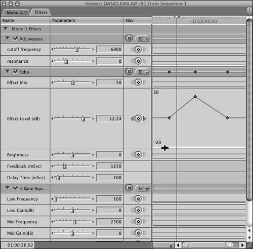 Adding and Smoothing Audio Keyframes To add a keyframe, click the diamond button on the right of the parameter you want to change, use the Pen tool (press P), or change the parameter during playback. All the audio filters can be modified in real time as long as you are working with a fast-enough computer. (Officially, you need any 500MHz G4 or faster, but dual CPUs perform more real-time effects at one time.) You can delete a keyframe in three ways. You can navigate to it using the arrows on either side of the diamond button and then click the diamond button to delete it. You can Ctrl-click the keyframe and select Clear. Finally, you can use the Delete Pen tool (press PP). You can change from a linear line to a curved and therefore " ramping " change over time in either keyframe area in two ways. You can create a keyframe by using the Smooth Pen tool (press PPP). You also can Ctrl-click a keyframe that was added with the Pen tool to reveal a context menu (see Figure 8.9). Smoothing a keyframe adds a bezier curve handle with a blue dot that you can drag to change the way the curve looks, and thus the way the parameter's effect changes over time. You might want to change the effect to ramp quickly, as shown in Figure 8.10, and then slowly reach its peak level. Or you could do the oppositeslow the change early and then ramp quickly to its peak level. Either way, the curve can be seen in both keyframe areas in the Viewer and in the Timeline beneath the clip. To change the curve, drag the blue dot on the bezier control. Figure 8.9. The context keyframe menu.  Figure 8.10. Using bezier curve handles to modify or "smooth" the keyframe's effect over time. 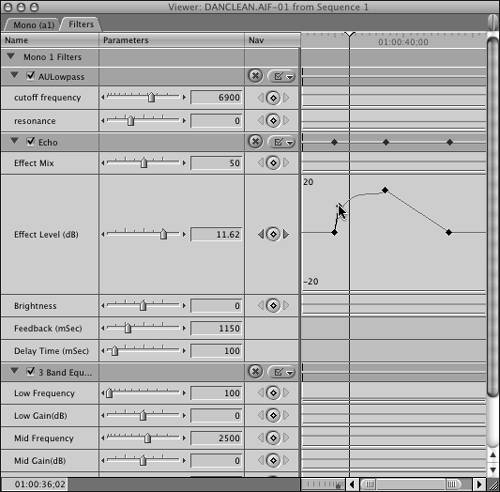 The Audio Filters Supplied in Final Cut Pro 4 This following sections describe the complete set of standard audio filters. As shown in Figures 8.1 and 8.2, they are broken into two sections: -
New to FCP 4, the Apple filters are supplied by the OS itself. These filters start with AU, which stands for audio units. -
The other set is the older "standard" set of filters supplied by Final Cut Pro. Both sets of filters operate basically the same way. Adding and modifying them also is done in basically the same way. As soon as your computer has reached its capacity to play back these filtered clips in real time, you hear a beeping sound. At this point, you can render the files you are happy with to add additional filters. As a side note, the audio unit filters come from Logic, Apple's professional audio application. They also appear in SoundTrack, where the Logic interface is optional. AUBandpass AUBandpass, shown in Figure 8.11, changes a single frequency band. By selecting the center frequency slider, you can modify the boost or cut level. You also can change the bandwidth value to narrow or widen the frequency range that is heard and the level of accentuation at the center of the band. A low bandwidth value results in less accentuation and wider audibility across the band. A high bandwidth value focuses more sharply on the center of the band you've chosen with the center frequency slider, screening out more of the frequencies above and below it. AUBandpass can be used to quickly attenuate a range of frequencies in a clip. It can be used to create effects, like the sound of someone talking over the telephone. Figure 8.11. AUBandpass.  AUDelay AUDelay, shown in Figure 8.12, adds repeats to the audio clip. You can also set the level (amount) of the effect (using the dry/wet mix), brightness using the lowpass cutoff frequency, feedback (duration of repeats), and delay (time between repeats.) The AUDelay filter is useful for creating a "slapback" or the sound you'd hear in a canyon sort of effect for the selected audio. Figure 8.12. AUDelay.  AUGraphicEQ AUGraphicEQ, shown in Figure 8.13, separates the audio into 31 frequency bands, ranging from 20Hz to 20,000Hz. You can set the center frequency for each band. This filter applies equalization in 31 bands of your clip at the same time rather than requiring you to apply multiple filters. It separates the EQ controls much like an audio mixing board does. Figure 8.13. AUGraphicEQ. 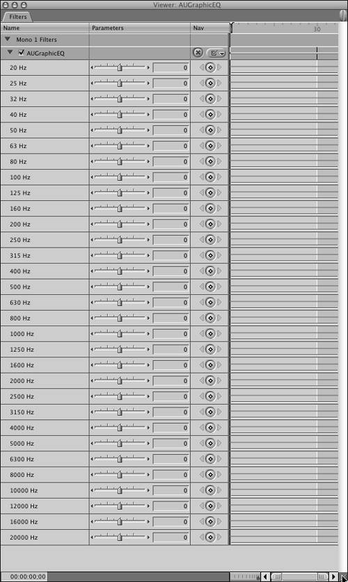 AUHighShelfFilter AUHighShelfFilter, shown in Figure 8.14, is much like the AUBandpass filter, but the higher end of the frequency range is sharply cut off. The lower-end frequencies are unaffected. You can use the gain setting to raise or lower the volume in the higher end of the frequency range. Figure 8.14. AUHighShelfFilter.  AUHipass AUHipass, shown in Figure 8.15, is also similar to the AUBandpass filter, but it modifies the low-end frequencies, leaving high frequencies alone. The AUHipass filter can be used to minimize sounds such as traffic rumble or an airplane's sound mixed with a voice, for example. Figure 8.15. AUHipass.  AULowpass AULowpass, shown in Figure 8.16, is another AUBandpass-type filter that reduces high-end frequencies, leaving low frequencies alone. This filter can be used to reduce bright-sounding noises such as tape hiss. Figure 8.16. AULowpass.  AULowShelfFilter AULowShelfFilter, shown in Figure 8.17, is another AUBandpass-type filter. The lower end of the frequency range is cut off, but high frequencies are unaffected. You can use the gain setting to boost or cut the sound at the lower end of the frequency range. Figure 8.17. AULowShelfFilter.  AUParametricEQ AUParametricEQ, shown in Figure 8.18, allows you to control a single frequency band. It combines the effects of the Bandpass, Notch , and Shelf filters. You set the Q value to narrow or widen the frequency range that is heard and the level of accentuation at the center of the band. A lower Q value gives less emphasis and wider audibility across the frequency band selected. A higher Q value focuses more sharply on the center of the band, screening out more of the higher and lower frequencies around the selected frequency. Figure 8.18. AUParametricEQ.  AUPeakLimiter Similar to a normalization filter, applying AUPeakLimiter levels out inconsistent volume levels in an audio clip, as shown in Figure 8.19. The attack and decay settings determine how quickly the effect changes the volume level. Figure 8.19. AUPeakLimiter.  3 Band Equalizer The 3 Band Equalizer, shown in Figure 8.20, divides the audio spectrum into three frequency bands: Low, Mid, and High. Low frequency adjusts between 80Hz and 2,000Hz, Mid Frequency adjusts between 400Hz and 8,000Hz, and High Frequency adjusts between 5,000Hz and 20,000Hz. Notice that they overlap. Figure 8.20. 3 Band Equalizer.  You can set the center frequency for each band and change the volume of each band relative to the others by modifying the Gain setting for each frequency. This is much like the EQ controls on most mixing boards . This filter equalizes three bands of your clip at the same time. You might use this control to add more bass, treble, or midrange to bring out the quality of the audio you want to hear more clearly. As with all the audio filters, each slider is keyframeable over time. If you open the Viewer window, you can see another set of "mini-Timelines" used for this purpose. Keep in mind that you should err on the side of not enough rather than too much. There are an endless number of reasons to use this filter. You might have to match an ADR reading when the original microphone is unavailable, for instance, or give a spokesperson a little more presence. Band Pass Filter Band Pass Filter, shown in Figure 8.21, lets you alter a single frequency band. By choosing the center frequency, you can change the boost or cut level. Unlike the 3 Band Equalizer, this filter has a Q slider, which determines a range value. Figure 8.21. Band Pass Filter.  You can alter the Q value to narrow or widen the frequency range that is heard or "passed" and the level of emphasis at the center of the band. A lower Q value gives less prominence and wider range across the band. A high Q value narrows the effect on the center of the band, eliminating more of the higher and lower frequencies. Band Pass Filter quickly makes a range of frequencies within a clip thinner (attenuates them). It's good for creating intense effects, such as the sound of someone's voice over the telephone. Compressor/Limiter Compressor/Limiter, shown in Figure 8.22, evens out inconsistencies in volume levels over time. It acts across all frequencies. Compression of volume reduces the dynamic range so that the audio level does not become too high. The more a level exceeds the limit you set, the more it is lowered in volume, depending on the Ratio setting. After making settings, you can click the Preserve Volume check box to keep the overall level close to the original. The Threshold setting determines the level at which the effect is initiated. The Attack and Release settings determine how fast or slow the change is initiated and then brought back to its original setting. This is especially useful for an actor who keeps moving to and from a microphone or whose delivery level is inconsistent. Figure 8.22. Compressor/Limiter.  DC Notch DC Notch, shown in Figure 8.23, compensates for a specific type of error in your audio track caused by DC current leakage. It allows you to remove a DC offset component, which might happen during recording. This filter is either on or off. Figure 8.23. DC Notch.  Echo Echo, shown in Figure 8.24, adds an echo. You can adjust the mix of the original source signal with the repeating sounds created by this filter. You can also set the level (amount) of the effect, brightness, feedback (duration of repeats), and delay (time between repeats). You can use the Echo filter to create the sound of someone walking in a canyon, for example. You need to add extra material beyond the end of the echo for the echo to fade out. The same is true of Reverberation. Keyframe the volume down before the clip ends. Figure 8.24. Echo.  Expander/Noise Gate Expander/Noise Gate, shown in Figure 8.25, evens out inconsistencies in volume levels over time by raising the volume if it drops below a specified level. The lower a level is relative to the highest level, the more it is increased to compensate, depending on where you've set the Ratio slider. Noise Gate silences all sound below the specified volume threshold. Like the Compressor/Limiter filter, you can adjust the attack time and release time. Doing so alters the amount of time between this filter's commencement and deactivation . This filter is similar to the Compressor/Limiter, but instead of lowering the loud levels, it raises the levels that are too low. Figure 8.25. Expander/Noise Gate.  High Pass Filter High Pass Filter, shown in Figure 8.26, is optimized to reduce low frequencies, leaving high frequencies alone. This filter is useful for reducing low noises such as rumbles or consistent low-pitched sounds such as air conditioners. To use it, you find the frequency of the offending noise and then adjust the Q slider to widen the range that will be affected. Figure 8.26. High Pass Filter.  High Shelf Filter With the High Shelf Filter, shown in Figure 8.27, the high frequencies are cut off, and the low frequencies are allowed to remain . You can use the Gain setting to boost or cut the volume in the higher end of the frequency range. Figure 8.27. High Shelf Filter.  Hum Remover Hum Remover, shown in Figure 8.28, is a notch filter that can compensate for cycle hum. Various things such as power lines can cause these hums. This filter's frequency usually matches the AC current used in the country you are recording in. So in Europe, it's likely around 50Hz, and in the U.S., around 60Hz. You can also specify up to five related harmonic frequencies to screen out as well by clicking the various buttons. Final Cut Pro sets them, but by clicking the various buttons , you can add to this notch filter additional frequencies that might be in your audio signal. Figure 8.28. Hum Remover.  tip You are more likely to find an offending hum on the harmonic frequency than on the primary main's frequencyparticularly the third harmonic. Notch out the minimum harmonics for the problem to be solved , because the harmonics are within audible audio and degrade the content. You might have to use the Q slider to narrow the range if the sound frequencies you want to preserve are near the hum's frequency.
Low Pass Filter Low Pass Filter, shown in Figure 8.29, is a Band Pass filter optimized to lower the level of high frequencies, leaving low frequencies alone. This filter is useful for dulling down a sound that is too "bright," reducing things such as tape hiss and machine noise from a clip. Similar to the High Shelf Filter, it leaves some of the high frequency instead of cutting it off. Figure 8.29. Low Pass Filter.  Low Shelf Filter Low Shelf Filter, shown in Figure 8.30, is similar to the Band Pass filter, but the lower end of the frequency range is sharply cut off, whereas high frequencies are allowed to pass. You can use the Gain setting to boost or lower the volume at the lower end of the frequency range. Figure 8.30. Low Shelf Filter.  Notch Filter Notch Filter, shown in Figure 8.31, cuts out frequencies in a specific range. As opposed to the other notch filters, this one works on a narrow range of frequencies. The Notch filter is useful for easing a specific frequency of sound that is overly loud. This effect is the opposite of a Band Pass filter. For example, if you have a sound that has a reverberating frequency that draws attention to itself, you can use the Notch filter to attenuate just that frequency so that it doesn't stand out. Figure 8.31. Notch Filter.  Parametric Equalizer The Parametric Equalizer, shown in Figure 8.32, is the most accommodating of Final Cut Pro's EQ filters. It allows you to control various aspects of a single frequency band. It combines the features of the Band Pass, Notch, and Shelf filters. It works the same as other EQ filters that contain a Q slider. You can set the Q value to narrow or widen the frequency range that is heard and the level of prominence at the center of the band. A low Q value results in less accentuation and wider audibility across the band. A high Q value focuses more sharply on the center of the band, screening out more of the frequencies above and below it. Figure 8.32. Parametric Equalizer.  Reverberation Reverberation, shown in Figure 8.33, adds the effect of being in various rooms, simulating the acoustic effect you would hear if you were in them. You might have recorded some sound in a booth with no room acoustic sound, creating a more-or-less dead sound. You can mix this recorded signal and the effect, as well as the effect's level (amount) and brightness. This effect provides a list of predefined room types or spaces that can be applied to your audio clip. You can start with one of the "preset" room ambiences and alter it to fit the sound that fits the picture or effect you are trying to create. As with the Echo filter, you need to leave some extra frames for a Reverberation filter to fade. Figure 8.33. Reverberation.  An obvious use of the filter is when you have shot your actors against a green screen and will key them in a huge room for a composite shot. You need to make them sound as if they are really in this huge room or tunnel to complete the total effect. Take a look at the "preset" rooms you can put them in. Sometimes this filter is useful when you need to match an ADR recording done in a sound booth to a shot where the original recording was done in one of the preset rooms. You can also use this as an effect filter, to have a voice-over recording sound as if it's from the past, for example. Vocal DeEsser Vocal DeEsser, shown in Figure 8.34, is a special-purpose filter that controls and reduces sibilant ("s") sounds. Some actors or voices overemphasize these sounds. The Vocal DeEsser reduces them. Experimenting with the various settings on this filter usually helps this condition. Figure 8.34. Vocal DeEsser.  Vocal DePopper Sometimes, especially if a microphone is not placed properly or the speaker or actor moves it during a performance, a wind noise is recorded. It's caused by a "p" sound that "pops" across the microphone because of a sudden puff of air being converted to noise picked up by the microphone. The Vocal DePopper, shown in Figure 8.35, controls and reduces this unwanted noise. Microphone screens don't always catch this, and you might not be able to stop a performance in progress. Figure 8.35. Vocal DePopper.  |