| The problem areas of IPsec can be categorized based on their implementations as follows: LAN-to-LAN Troubleshooting This section presents the configuration and troubleshooting steps of IPsec LAN-to-LAN VPN tunnel between two PIXen based on Figure 7-1. Figure 7-1. Typical LAN-to-LAN and Remote Access VPN Setup 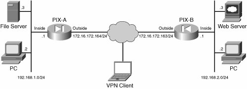
As shown in Figure 7-1, PIX-A and PIX-B are running PIX version 7.0 and are configured for a LAN-to-LAN tunnel. The troubleshooting steps that follow the configuration steps use the same setup as shown in Figure 7-1. Configuration Steps Work through the steps that follow to configure a basic LAN-to-LAN IPsec tunnel between two PIX firewalls: | | Step 1. | Configure the basic PIX firewall.
Before you attempt to configure LAN-to-LAN VPN tunnel, you need to configure the interface and the routing on the PIX firewall. Example 7-6 shows how to configure the outside interface of the PIX firewall and define the route. The same procedure can be used to configure the rest of the interfaces on the PIX firewall.
Example 7-6. Configuring Interfaces on the PIX Firewall ! From configuration mode, go under interface configuration mode. PIX-A(config)# interface ethernet0 ! Assign the IP address and subnet mask for the interface PIX-A(config-if)# ip address 172.16.172.164 255.255.255.0 ! Name the interface with the nameif command. If you define the name as outside ! interface, the security level is set to zero. PIX-A(config-if)# nameif outside !Set the speed and duplex with the following two lines. PIX-A(config-if)# speed auto PIX-A(config-if)# duplex full ! You can set the security level with the security-level command. The following line ! is not necessary if the interface is named as outside. PIX-A(config-if)# security-level 0 ! Enable the interface with the following command. PIX-A(config-if)# no shutdown ! Define the default gateway or more specific static route for private network ! of the other side of the tunnel. PIX-A(config-if)# route outside 0.0.0.0 0.0.0.0 172.16.172.1 PIX-A(config-if)#
|
| Step 2. | Configure ISAKMP policy and enable on the outside interface.
To configure ISAKMP policies, in global configuration mode, use the isakmp policy command with its various arguments. The syntax for ISAKMP policy commands is:
isakmp policy priority attribute_name [attribute_value | integer]
Example 7-7 shows how to configure the ISAKMP policy on the PIX firewall.
Example 7-7. ISAKMP Policy Configuration on PIX Firewall ! Set the authentication method as pre-shared key with the following command. PIX-A(config)# isakmp policy 20 authentication pre-share ! Encryption key method is defined as 3DES with the following command. PIX-A(config)# isakmp policy 20 encryption 3des ! Hashing algorithm is defined as MD5 for this example. PIX-A(config)# isakmp policy 20 hash md5 ! Set the Diffie-Hellman group 2 with the following command. PIX-A(config)# isakmp policy 20 group 2 ! The default timeout value is 28800 or 8 hours. Following command set up the ! timeout value to be 12 hours. PIX-A(config)# isakmp policy 20 lifetime 43200 ! Enable ISAKMP on the outside interface. PIX-A(config)# isakmp enable outside PIX-A(config)#
|
| | | Step 3. | Create a transform set.
A transform set combines an encryption method and an authentication method. During the IPsec security association negotiation with ISAKMP, the peers agree to use a particular transform set to protect a particular data flow. The transform set must be the same for both peers.
You can create multiple transform sets, and then specify one or more of these transform sets in a crypto map entry. PIX firewall uses the transform set information to protect the data flows for that crypto map entry access list. For more overview information, refer to the section in this chapter entitled "Creating a Transform Set" in "LAN-to-LAN Troubleshooting."
To configure a transform set, in global configuration mode, use the crypto ipsec transform-set command. The syntax is:
crypto ipsec transform-set transform-set-name encryption-method authentication-method
Example 7-8 configures a transform set with the name myset, esp-3des encryption, and esp-md5-hmac authentication.
Example 7-8. Configuring Transform Set on the PIX Firewall PIX-A(config)# crypto ipsec transform set myset esp-3des esp-md5-hmac PIX-A(config)#
|
| | | Step 4. | Configure an Access-list (ACL) to define Interesting Traffic for LAN-to-LAN IPsec tunnel.
The access-list in LAN-to-LAN IPsec tunnel is used to define the interesting traffic between the tunnel end points of the PIX firewalls that needs to be protected by the tunnel. To configure an ACL, use the following syntax:
access-list listname extended permit ip source-ipaddress source-netmask destination-ipaddress destination-netmask
Example 7-9 shows an access-list configuration (ACL 101) on PIX-A that protects the traffic between two private networks (between PIX-A and PIX-B). The source network for the access-list on PIX-A is 192.168.1.0/24 and destination network is 192.168.2.0/24.
Example 7-9. Defining Interesting Traffic by Access List on PIX-A Firewall PIX-A(config)# access-list l0l_extended permit ip 192.168.1.0 255.255.255.0 192.168.2.0 255.255.255.0 PIX-A(config)#
|
You must configure a mirror image access-list on the other side of the tunnel (PIX-B) to define the interesting traffic for the IPsec tunnel as shown in Example 7-10.
Example 7-10. Mirror Image ACL on PIX-B Firewall to Define IPsec LAN-to-LAN Tunnel Interesting Traffic PIX-B(config)# access-list l0l_extended permit ip 192.168.2.0 255.255.255.0 192.168.1.0 255.255.255.0 PIX-B(config)#
|
Note that this access-list is the mirror image of the ACL defined on PIX-A firewall.
| Step 5. | Define a tunnel group for a LAN-to-LAN tunnel.
A tunnel group is used to identify AAA servers, specify connection parameters, and define a default group policy. PIX Firewall stores tunnel groups internally. There are two default tunnel groups in the PIX firewall: DefaultRAGroup, which is the default IPsec remote-access tunnel group; and DefaultL2Lgroup, which is the default IPsec LAN-to-LAN tunnel group. You can change them but not delete them. To establish a basic LAN-to-LAN VPN connection, you must configure the following two attributes for a tunnel group:
- (a). Set up the connection type to be IPsec_L2L (IPsec LAN-to-LAN tunnel) with the configuration shown in Example 7-11. Be sure to define the tunnel name with the peer's IP address. This is how the PIX firewall identifies the tunnel group for authentication.
Example 7-11. Creating LAN-to-LAN VPN Tunnel-Group on PIX Firewall PIX-A(config)# Tunnel-Group 172.16.172.163 type IPsec_L2L PIX-A(config)#
|
- (b). Define the pre-shared key as shown in Example 7-12.
Example 7-12. Configuration of the Pre-shared Key for LAN-to-LAN IPsec Tunnel PIX-A(config)# tunnel-group 172.16.172.163 ipsec-attributes PIX-A(config-ipsec)# pre-shared-key cisco123 PIX-A(config)#
|
| | | Step 6. | Create a crypto map for a LAN-to-LAN tunnel.
The crypto map applied on the interface triggers the IPsec process. Several components are tied together with the crypto map command. As you can apply only one crypto map per interface, you must create the crypto map with the same name but different sequence number to provide different security for different subnets. Also, if you have different peers, you need to create multiple entries of the crypto map with different sequence numbers but with the same name.
Example 7-13 shows how to create a crypto map on PIX-A firewall for the LAN-to-LAN tunnel with PIX-B firewall.
Example 7-13. Creating Crypto Map on the PIX-A Firewall for LAN-to-LAN Tunnel ! Assign the access-list previously created to the crypto map entry. PIX-A(config)# crypto map mymap 10 match address 101 ! Define the Peer IP address with the following command. PIX-A(config)# crypto map mymap 10 set peer 172.16.172.163 ! Apply the transform set to the crypto map. You can apply multiple transform ! sets to the same crypto map. PIX-A(config)# crypto map mymap 10 set transform-set myset PIX-A(config)#
|
Apply the crypto map to an interface. Once a crypto map is configured, you need to apply it on the outgoing interface of the packet destination. Applying a crypto map is supported on all interfaces of the PIX firewall. When you make any changes to the applied crypto map, PIX firewall automatically applies the changes to the running configuration. It drops any existing connections and reestablishes them after applying the new crypto map. The syntax for applying the crypto map is as follows:
crypto map map-name interface interface-name
Example 7-14 shows how to apply the crypto map on the outside interface of PIX firewall PIX-A.
Example 7-14. Applying the Crypto Map on the Outside Interface of PIX-A PIX-A(config)# crypto map mymap interface outside PIX-A(config)#
|
| | | Step 7. | Bypass the NAT translation for the IPsec VPN traffic.
If you have nat-control turned off on the PIX firewall, you do not need any special configuration to create the NAT exemption for the LAN-to-LAN VPN traffic unless you have NAT configured that translates the source network of the VPN traffic to a routable IP address. Under this circumstance, or when the nat-control is turned on, you must bypass the NAT for the private networks of the VPN traffic. You can understand this best by looking at an example. Assume that network 192.168.1.0/24 on PIX-A is translated to the interface IP address (172.16.172.164) for the Internet connection with the nat/global statement. With this setup, whether you have the nat-control turned on or off, you need to configure the NAT exemption to allow the LAN-to-LAN private network to bypass the NAT. This is because even if you have the nat-control off, PIX still performs the NAT translation if it is configured. When the nat-control is tuned on, PIX must perform the NAT translation, hence NAT exemption is a must for the VPN traffic. Example 7-15 shows how to configure the NAT exemption for the LAN-to-LAN VPN traffic.
Example 7-15. Bypassing the LAN-to-LAN VPN Traffic Across the Tunnel PIX-A(config)# show running-config nat-control ! The following line indicates that the nat-control is turned off no nat-control ! Now check to see if there is a NAT configured that may include the private ! network that needs to be protected by the IPSec tunnel PIX-A(config)# show running-config nat ! The following line indicates the NAT is configured for the source network of ! the VPN traffic that needs to be protected by the tunnel. nat (inside) 1 192.168.1.0 255.255.255.0 ! The following command verifies the corresponding global stmt, which says all ! internet bound traffic uses the outside interface IP address. PIX-A(config)# show running-config global global (outside) 1 interface ! To bypass the LAN-to-LAN VPN traffic, create a new ACL or use the existing ! crypto ACL which is 101 on the PIX firewall with the source and destination ! addresses to be the private networks on both sides. PIX-A(config)# access-list 110 extended permit ip 192.168.1.0 255.255.255.0 192.168.2.0 255.255.255.0 ! Apply the ACL with NAT statement to configure NAT exemption. PIX-A(config)# nat (inside) 0 access-list 110 ! Following line verifies the NAT configuration PIX-A(config)# show running-config nat nat (inside) 0 access-list 110 nat (inside) 1 192.168.1.0 255.255.255.0 ! Following line verifies the ACL configuration PIX-A(config)# show running-config access-list 110 access-list 110 extended permit ip 192.168.1.0 255.255.255.0 192.168.2.0 255.255.255.0 PIX-A(config)#
|
| | | Step 8. | Allow the actual IPsec traffic through the tunnel.
You must allow the decrypted IPsec tunnel traffic with either the sysopt command or by creating an access-list to allow the private networks, and to apply the access-list on the outside interface as inbound. Example 7-16 shows how to allow the decrypted packets on the PIX outside interface by using the sysopt command or access-list.
Example 7-16. Configuration to Bypass ACL Checks to Allow the Decrypted Traffic ! Use the sysopt command in global configuration mode to have the PIX firewall ! to allow IPSec connections. PIX-A(config)# sysopt connection permit-ipsec ! The following ACL substitute the sysopt command. The source address of the ACL ! is the network or addresses defined with IP address Pool. PIX-A(config)# access-list 120 permit 192.168.2.0 255.255.255.0 192.168.1.0 255.255.255.0 ! Apply the access-list to the interface PIX-A(config)# access-group 120 in interface outside ! Save your changes. PIX-A(config)# write memory PIX-A(config)#
|
Follow the preceding steps to configure PIX-B firewall. Example 7-17 shows the configuration that needs to be performed for LAN-to-LAN tunnel.
Example 7-17. Configuration on the PIX-B Firewall for the LAN-to-LAN Tunnel ! Following lines are for configuring interface PIX-B(config)# interface ethernet0 PIX-B(config-if)# ip address 172.16.172.163 255.255.255.0 PIX-B(config-if)# nameif outside PIX-B(config-if)# speed auto PIX-B(config-if)# duplex full PIX-B(config-if)# no shutdown ! Following lines are to define ISAKMP policy which should match to one of the policies ! defined on PIX-A PIX-B(config)# isakmp policy 10 authentication pre-share PIX-B(config)# isakmp policy 10 encryption 3des PIX-B(config)# isakmp policy 10 hash md5 PIX-B(config)# isakmp policy 10 group 2 PIX-B(config)# isakmp policy 10 lifetime 43200 PIX-B(config)# isakmp enable outside ! Following line defines the transform-set PIX-B(config)# crypto ipsec transform set myset esp-3des esp-md5-hmac ! Following line defines the ACL for the interesting traffic for LAN-to-LAN VPN PIX-B(config)# access-list l01_list extended permit ip 192.168.2.0 255.255.255.0 192.168.1.0 255.255.255.0 ! Define the tunnel-group with the name to be the peer's IP address, i.e, PIX-A's outside ! interface IP address. The pre-shared-key has to match on both sides. PIX-B(config)# tunnel-group 172.16.172.164 type IPSec_L2L PIX-B(config)# tunnel-group 172.16.172.164 ipsec-attributes PIX-B(config-ipsec)# pre-shared-key cisco123 ! The following lines are used to configure the crypto map PIX-B(config)# crypto map mymap 10 match address 101 PIX-B(config)# crypto map mymap 10 set peer anyhost 172.16.172.164 PIX-B(config)# crypto map mymap 10 set transform-set myset PIX-B(config)# crypto map mymap interface outside ! Configure sysopt for IPSec to allow the decrypted traffic on the outside interface PIX-B(config)# sysopt connection permit-ipsec ! For additional configuration on NAT and others, refer to the previous configuration ! steps for the PIX-A firewall PIX-B(config)# write memory PIX-B(config)#
|
|
Troubleshooting Steps The LAN-to-LAN IPsec tunnel may fail to process traffic for several reasons. This section examines the details of all possible causes and how to resolve them. The troubleshooting IPsec LAN-to-LAN tunnel issues can classified as follows: Tunnel is not established: Phase I failure Tunnel is not established: Phase II failure Tunnel is established completely but unable to pass data
The sections that follow provide a detailed discussion of these topics. Tunnel Is Not Established: Phase I Failure If you are unable to pass any traffic across the LAN-to-LAN IPsec tunnel, you should first investigate the status of the tunnel state on both the Initiator and the Responder PIXen. You might experience tunnel establishment failure either in Phase I or Phase II. For successful tunnel establishment, you must have both Phase I And Phase II established. The Show crypto isakmp sa command allows you to view the status of the tunnel, and if it is MM_ACTIVE, this means that the Phase I is established, as shown in Example 7-18. PIX versions earlier than 7.0 shows QM_IDLE for phase I establishment. Example 7-18. A Successful Phase I Establishment on PIX Version 7.0 and Later PIX-A# show crypto isakmp sa Active SA: 1 Rekey SA: 0 (A tunnel will report 1 Active and 1 Rekey SA during rekey) Total IKE SA: 1 1 IKE Peer: 172.16.172.163 Type : L2L Role : initiator ! The following line shows MM_ACTIVE for the initiator state which is an indication that ! Phase I is established. Rekey : no State : MM_ACTIVE PIX-A#
|
If Phase II is established, show crypto ipsec sa will provide the details as shown in Example 7-19. Example 7-19. Phase II Establishment of Tunnel on PIX Version 7.0 PIX-A# show crypto ipsec sa interface: outside ! The following line shows the crypto map name and the peer IP address Crypto map tag: mymap, local addr: 172.16.172.164 ! The following two lines show the private networks of both sides whose traffic ! will be protected by the IPSec tunnel. local ident (addr/mask/prot/port): (192.168.1.0/255.255.255.0/0/0) remote ident (addr/mask/prot/port): (192.168.2.0/255.255.255.0/0/0) current_peer: 172.16.172.163 ! The following counters are extremely important to see if the tunnel is processing any ! traffic. Encaps indicates that this side is encrypting and sending the traffic fine to ! the other side. And decrypts counter indicates that the other side is sending the reply ! and this is able to decrypt the traffic. #pkts encaps: 4, #pkts encrypt: 4, #pkts digest: 4 #pkts decaps: 4, #pkts decrypt: 4, #pkts verify: 4 #pkts compressed: 0, #pkts decompressed: 0 #pkts not compressed: 4, #pkts comp failed: 0, #pkts decomp failed: 0 #send errors: 0, #recv errors: 0 local crypto endpt.: 172.16.172.164, remote crypto endpt.: 172.16.172.163 path mtu 1500, ipsec overhead 60, media mtu 1500 current outbound spi: 88BB86AD ! The following inbound SA has an SPI number indicating that this is established. inbound esp sas: spi: 0x1A280A9D (438831773) transform: esp-3des esp-md5-hmac in use settings ={L2L, Tunnel, } slot: 0, conn_id: 1, crypto-map: mymap sa timing: remaining key lifetime (kB/sec): (4274999/28776) IV size: 8 bytes replay detection support: Y ! The following outbound SA has an SPI number indicating that this is established. outbound esp sas: spi: 0x88BB86AD (2293991085) transform: esp-3des esp-md5-hmac in use settings ={L2L, Tunnel, } slot: 0, conn_id: 1, crypto-map: mymap sa timing: remaining key lifetime (kB/sec): (4274999/28774) IV size: 8 bytes replay detection support: Y PIX-A#
|
Before exploring failure or possible causes of failure for Phase I and Phase II, it is worth dissecting the debug output of a successful LAN-to-LAN IPsec tunnel on the Initiator side, which is shown in Example 7-20. Example 7-20. Dissection of debug Commands for a Successful IPsec Tunnel| [View full width] PIX-A# debug crypto isakmp 7 PIX-A# debug crypto ipsec 7 ! Usually level 5 will give you the details to troubleshoot most of the issues. ! Sometimes, you may run level 7. Rarely you may need to run level 255. Jun 05 21:38:55 [IKEv1 DEBUG]: pitcher: received a key acquire message! ! The following line shows the initiation of the first packet for IPSec tunnel by the ! Initiator. Jun 05 21:38:55 [IKEv1]: IP = 172.16.172.163, IKE Initiator: New Phase 1, Intf 2, IKE Peer 172.16.172.163 local Proxy Address 192.168.1.0, remote Proxy Address 192.168.2.0, Crypto map (mymap) Jun 05 21:38:55 [IKEv1 DEBUG]: IP = 172.16.172.163, constructing ISA_SA for isakmp Jun 05 21:38:55 [IKEv1 DEBUG]: IP = 172.16.172.163, constructing Fragmentation VID + extended capabilities payload Jun 05 21:38:55 [IKEv1]: IP = 172.16.172.163, IKE DECODE SENDING Message (msgid=0) with payloads : HDR + SA (1) + VENDOR (13) + NONE (0) total length : 144 Jun 05 21:38:56 [IKEv1]: IP = 172.16.172.163, IKE DECODE RECEIVED Message (msgid=0) with payloads : HDR + SA (1) + VENDOR (13) + NONE (0) total length : 104 Jun 05 21:38:56 [IKEv1 DEBUG]: IP = 172.16.172.163, processing SA payload ! The following line indicates that IKE phase I policy is accepted by the other side Jun 05 21:38:56 [IKEv1 DEBUG]: IP = 172.16.172.163, Oakley proposal is acceptable Jun 05 21:38:56 [IKEv1 DEBUG]: IP = 172.16.172.163, processing VID payload Jun 05 21:38:56 [IKEv1 DEBUG]: IP = 172.16.172.163, Received Fragmentation VID Jun 05 21:38:56 [IKEv1 DEBUG]: IP = 172.16.172.163, IKE Peer included IKE fragmentation capability flags: Main Mode: True Aggressive Mode: True Jun 05 21:38:56 [IKEv1 DEBUG]: IP = 172.16.172.163, constructing ke payload Jun 05 21:38:56 [IKEv1 DEBUG]: IP = 172.16.172.163, constructing nonce payload Jun 05 21:38:56 [IKEv1 DEBUG]: IP = 172.16.172.163, constructing Cisco Unity VID payload Jun 05 21:38:56 [IKEv1 DEBUG]: IP = 172.16.172.163, constructing xauth V6 VID payload Jun 05 21:38:56 [IKEv1 DEBUG]: IP = 172.16.172.163, Send IOS VID Jun 05 21:38:56 [IKEv1 DEBUG]: IP = 172.16.172.163, Constructing ASA spoofing IOS Vendor ID payload (version: 1.0.0, capabilities: 20000001) Jun 05 21:38:56 [IKEv1 DEBUG]: IP = 172.16.172.163, constructing VID payload Jun 05 21:38:56 [IKEv1 DEBUG]: IP = 172.16.172.163, Send Altiga/Cisco VPN3000/Cisco ASA GW VID Jun 05 21:38:56 [IKEv1]: IP = 172.16.172.163, IKE DECODE SENDING Message (msgid=0) with payloads : HDR + KE (4) + NONCE (10) + VENDOR (13) + VENDOR (13) + VENDOR (13) + VENDOR (13) + NONE (0) total length : 256 Jun 05 21:38:56 [IKEv1]: IP = 172.16.172.163, IKE DECODE RECEIVED Message (msgid=0) with payloads : HDR + KE (4) + NONCE (10) + VENDOR (13) + VENDOR (13) + VENDOR (13) + VENDOR (13) + NONE (0) total length : 256 Jun 05 21:38:56 [IKEv1 DEBUG]: IP = 172.16.172.163, processing ke payload Jun 05 21:38:56 [IKEv1 DEBUG]: IP = 172.16.172.163, processing ISA_KE Jun 05 21:38:56 [IKEv1 DEBUG]: IP = 172.16.172.163, processing nonce payload Jun 05 21:38:56 [IKEv1 DEBUG]: IP = 172.16.172.163, processing VID payload Jun 05 21:38:56 [IKEv1 DEBUG]: IP = 172.16.172.163, Received Cisco Unity client VID Jun 05 21:38:56 [IKEv1 DEBUG]: IP = 172.16.172.163, processing VID payload Jun 05 21:38:56 [IKEv1 DEBUG]: IP = 172.16.172.163, Received xauth V6 VID Jun 05 21:38:56 [IKEv1 DEBUG]: IP = 172.16.172.163, processing VID payload Jun 05 21:38:56 [IKEv1 DEBUG]: IP = 172.16.172.163, Processing VPN3000/ASA spoofing IOS Vendor ID payload (version: 1.0.0, capabilities: 20000001) Jun 05 21:38:56 [IKEv1 DEBUG]: IP = 172.16.172.163, processing VID payload Jun 05 21:38:56 [IKEv1 DEBUG]: IP = 172.16.172.163, Received Altiga/Cisco VPN3000/ Cisco ASA GW VID ! The following shows that the tunnel group configuration is found. This is where the ! pre-shared key is defined. Jun 05 21:38:56 [IKEv1]: IP = 172.16.172.163, Connection landed on tunnel_group 172.16.172.163 Jun 05 21:38:56 [IKEv1 DEBUG]: Group = 172.16.172.163, IP = 172.16.172.163, Generating keys for Initiator... Jun 05 21:38:56 [IKEv1 DEBUG]: Group = 172.16.172.163, IP = 172.16.172.163, constructing ID Jun 05 21:38:56 [IKEv1 DEBUG]: Group = 172.16.172.163, IP = 172.16.172.163, construct hash payload Jun 05 21:38:56 [IKEv1 DEBUG]: Group = 172.16.172.163, IP = 172.16.172.163, computing hash Jun 05 21:38:56 [IKEv1 DEBUG]: IP = 172.16.172.163, Constructing IOS keep alive payload: proposal=32767/32767 sec. Jun 05 21:38:56 [IKEv1 DEBUG]: Group = 172.16.172.163, IP = 172.16.172.163, constructing dpd vid payload Jun 05 21:38:56 [IKEv1]: IP = 172.16.172.163, IKE DECODE SENDING Message (msgid=0) with payloads : HDR + ID (5) + HASH (8) + IOS KEEPALIVE (14) + VENDOR (13) + NONE (0) total length : 92 Jun 05 21:38:56 [IKEv1]: IP = 172.16.172.163, IKE DECODE RECEIVED Message (msgid=0) with payloads : HDR + ID (5) + HASH (8) + IOS KEEPALIVE (14) + VENDOR (13) + NONE (0) total length : 92 Jun 05 21:38:56 [IKEv1 DEBUG]: Group = 172.16.172.163, IP = 172.16.172.163, Processing ID Jun 05 21:38:56 [IKEv1 DEBUG]: Group = 172.16.172.163, IP = 172.16.172.163, processing hash Jun 05 21:38:56 [IKEv1 DEBUG]: Group = 172.16.172.163, IP = 172.16.172.163, computing hash Jun 05 21:38:56 [IKEv1 DEBUG]: IP = 172.16.172.163, Processing IOS keep alive payload: proposal=32767/32767 sec. Jun 05 21:38:56 [IKEv1 DEBUG]: Group = 172.16.172.163, IP = 172.16.172.163, processing VID payload Jun 05 21:38:56 [IKEv1 DEBUG]: Group = 172.16.172.163, IP = 172.16.172.163, Received DPD VID Jun 05 21:38:56 [IKEv1]: IP = 172.16.172.163, Connection landed on tunnel_group 172.16.172.163 ! Following line is an indication of phase I establishment and the beginning of phase II ! negotiation. Jun 05 21:38:56 [IKEv1 DEBUG]: Group = 172.16.172.163, IP = 172.16.172.163, Oakley begin quick mode ! The following message affirms the phase I establishment Jun 05 21:38:56 [IKEv1]: Group = 172.16.172.163, IP = 172.16.172.163, PHASE 1 COMPLETED Jun 05 21:38:56 [IKEv1]: IP = 172.16.172.163, Keep-alive type for this connection: DPD Jun 05 21:38:56 [IKEv1 DEBUG]: Group = 172.16.172.163, IP = 172.16.172.163, Starting phase 1 rekey timer: 41040000 (ms) Jun 05 21:38:56 [IKEv1 DEBUG]: IKE got SPI from key engine: SPI = 0xbb5bb46c Jun 05 21:38:56 [IKEv1 DEBUG]: Group = 172.16.172.163, IP = 172.16.172.163, oakley constructing quick mode Jun 05 21:38:56 [IKEv1 DEBUG]: Group = 172.16.172.163, IP = 172.16.172.163, constructing blank hash Jun 05 21:38:56 [IKEv1 DEBUG]: Group = 172.16.172.163, IP = 172.16.172.163, constructing ISA_SA for ipsec Jun 05 21:38:56 [IKEv1 DEBUG]: Group = 172.16.172.163, IP = 172.16.172.163, constructing ipsec nonce payload Jun 05 21:38:56 [IKEv1 DEBUG]: Group = 172.16.172.163, IP = 172.16.172.163, constructing proxy ID ! The following lines show the interesting traffic ACL getting exchanged. These ACL ! should be the mirror image of each other. Jun 05 21:38:56 [IKEv1 DEBUG]: Group = 172.16.172.163, IP = 172.16.172.163, Transmitting Proxy Id: Local subnet: 192.168.1.0 mask 255.255.255.0 Protocol 0 Port 0 Remote subnet: 192.168.2.0 Mask 255.255.255.0 Protocol 0 Port 0 Jun 05 21:38:56 [IKEv1 DEBUG]: Group = 172.16.172.163, IP = 172.16.172.163, constructing qm hash Jun 05 21:38:56 [IKEv1]: IP = 172.16.172.163, IKE DECODE SENDING Message (msgid=529335a6) with payloads : HDR + HASH (8) + SA (1) + NONCE (10) + ID (5) + ID (5) + NOTIFY (11) + NONE (0) total length : 192 Jun 05 21:38:57 [IKEv1]: IP = 172.16.172.163, IKE DECODE RECEIVED Message (msgid=529335a6) with payloads : HDR + HASH (8) + SA (1) + NONCE (10) + ID (5) + ID (5) + NONE (0) total length : 164 Jun 05 21:38:57 [IKEv1 DEBUG]: Group = 172.16.172.163, IP = 172.16.172.163, processing hash Jun 05 21:38:57 [IKEv1 DEBUG]: Group = 172.16.172.163, IP = 172.16.172.163, processing SA payload Jun 05 21:38:57 [IKEv1 DEBUG]: Group = 172.16.172.163, IP = 172.16.172.163, processing nonce payload Jun 05 21:38:57 [IKEv1 DEBUG]: Group = 172.16.172.163, IP = 172.16.172.163, Processing ID Jun 05 21:38:57 [IKEv1 DEBUG]: Group = 172.16.172.163, IP = 172.16.172.163, Processing ID Jun 05 21:38:57 [IKEv1 DEBUG]: Group = 172.16.172.163, IP = 172.16.172.163, loading all IPSEC SAs Jun 05 21:38:57 [IKEv1 DEBUG]: Group = 172.16.172.163, IP = 172.16.172.163, Generating Quick Mode Key! Jun 05 21:38:57 [IKEv1 DEBUG]: Group = 172.16.172.163, IP = 172.16.172.163, Generating Quick Mode Key! ! The negotiation for phase II shows completed here. Jun 05 21:38:57 [IKEv1]: Group = 172.16.172.163, IP = 172.16.172.163, Security negotiation complete for LAN-to-LAN Group (172.16.172.163) Initiator, Inbound SPI = 0xbb5bb46c, Outbound SPI = 0x7ea88a9e Jun 05 21:38:57 [IKEv1 DEBUG]: Group = 172.16.172.163, IP = 172.16.172.163, oakley constructing final quick mode Jun 05 21:38:57 [IKEv1]: IP = 172.16.172.163, IKE DECODE SENDING Message (msgid=529335a6) with payloads : HDR + HASH (8) + NONE (0) total length : 72 Jun 05 21:38:57 [IKEv1 DEBUG]: IKE got a KEY_ADD msg for SA: SPI = 0x7ea88a9e Jun 05 21:38:57 [IKEv1 DEBUG]: pitcher: rcv KEY_UPDATE, spi 0xbb5bb46c Jun 05 21:38:57 [IKEv1]: Group = 172.16.172.163, IP = 172.16.172.163, Starting P2 Rekey  timer to expire in 27360 seconds ! The following line confirms phase II completion, hence complete establishment of IPSec ! LAN-to-LAN tunnel. Jun 05 21:38:57 [IKEv1]: Group = 172.16.172.163, IP = 172.16.172.163, PHASE 2 COMPLETED (msgid=529335a6) PIX-A# timer to expire in 27360 seconds ! The following line confirms phase II completion, hence complete establishment of IPSec ! LAN-to-LAN tunnel. Jun 05 21:38:57 [IKEv1]: Group = 172.16.172.163, IP = 172.16.172.163, PHASE 2 COMPLETED (msgid=529335a6) PIX-A#
|
Now that you are comfortable with the show and debug command output of a successful IPsec LAN-to-LAN tunnel, if your Phase I for tunnel build-up fails, work through the following steps to correct the problem: Step 1. | Check for connectivity problems.
If you have problems with phase I establishment, first be sure that you can ping the responder from the initiator, and vice versa. This will ensure that you have proper routing configured for the peer IP address. If the peer IP address is not reachable, then Phase I negotiation will not take place.
| | | Step 2. | Be sure you get IKE Packets in the Initiator Debug Output.
If all parameters are configured properly on the Initiator, you should see the IKE packets with the debug crypto ISAKMP command. If you do not see any debug output, then work through the following steps to correct the problem:
- ISAKMP is turned offUnlike Cisco IOS router, ISAKMP is disabled by default on the PIX Firewall. So, if you do not turn it on, ISAKMP will not be triggered, and debug will not show any IKE packets. You can verify this by executing the command shown in Example 7-21. This example also shows how to enable ISAKMP on the interface. Example 7-21. Verifying and Correcting the Problem of ISAKMP Not Being Applied PIX-A(config)# show running-config isakmp | include enable ! As nothing is shown, ISAKMP is not turned on the interface. The following ! command shows how to turn on ISAKMP on the outside interface PIX-A(config)# show running-config isakmp | include enable ! The following line indicates that ISAKMP is enabled on the outside interface. isakmp enable outside PIX-A(config)# exit PIX-A#
|
- Routing Problem on the InitiatorIf ISAKMP is enabled on the interface, but you still do not see the IKE packets on the initiator debug, you may have problems with routing on the initiator. You must have a route on the initiator (PIX-A) for the private network (192.168.2.0/24) of the responder (PIX-B), which is pointing towards the interface where ISAKMP is applied. This can be done either through a static route or default gateway. Example 7-22 shows how to verify whether the route exists on the routing table for the private network. Example 7-22. Verifying that a Route for the Private Network Exists Through Outside Interface for the Responder Private Network PIX-A(config)# show route ! The following default gateway is on the outside interface of the PIX firewall ! where ISAKMP is applied. This is how the private network that needs to be ! protected via tunnel can be reached. The requirement is that the private ! traffic that needs to be go through the tunnel needs to hit the interface (in ! this case outside interface) where the crypto map and ISAKMP is applied. S 0.0.0.0 0.0.0.0 [1/0] via 172.16.172.1, outside ! The following two lines are for directly connected networks C 172.16.172.0 255.255.255.0 is directly connected, outside C 192.168.1.0 255.255.255.0 is directly connected, inside PIX-A(config)#
|
- Crypto Map is not applied or is applied to the wrong interfaceAfter verifying and fixing the routing problem on the initiator for the private network of the responder, if you are still unable to see IKE packets, be sure that you have crypto map applied to the outgoing interface. This is the interface through which the private network on the Responder will be reached by the initiator as per the routing table, even though the packet may not be able to reach due to the private address. However, sending the packet on the outgoing interface is required to trigger Phase II And Phase I of the PIX Firewall. If the crypto map is not applied, or applied on the wrong interface, Phase I will not come up as it is brought into action by the crypto map. Use the command shown in Example 7-23 to verify if and where the crypto map is applied. Example 7-23. Initiator (PIX-A) Properly Has the Crypto Map Applied on the Outside Interface of the PIX Firewall PIX-A# show running-config crypto map | include interface crypto map mymap interface outside PIX-A#
|
- The incorrect interesting traffic access-list is configuredThe traffic that needs to go through the tunnel is defined by the access-list that is applied to the crypto map. So, if the access-list does not include the source or destination network that should go through the tunnel, the tunnel will not be triggered, even if everything else is configured correctly. Remember that this access-list needs to be configured as mirror images on the initiator and responder. Example 7-24 shows that the access-list is properly configured on the PIX-A. Example 7-24. Access-list Configured on the Initiator (PIX-A) PIX-A# show running-config crypto | include address ! Following line indicates access-list 101 is applied to crypto map crypto map mymap 10 match address 101 PIX-A# show running-config access-list 101 ! Following line shows the network for which ACL is configured that needs to be ! protected by the IPSec tunnel. access-list 101 extended permit ip 192.168.1.0 255.255.255.0 192.168.2.0 255.255.255.0 PIX-A#
|
- Tunnel group is not configured, or is configured with the wrong peer IP addressIf you do not have the tunnel group configured on the initiator/responder, or it is configured with the wrong Peer IP address for the tunnel-group name, Phase I will not be established. Example 7-25 shows the debug message that appears on the initiator (PIX-A), when the tunnel group is not configured with the IP address of the peer (PIX-B).
Example 7-25. debug Message on the Initiator when the Tunnel Group Is Not Configured PIX-A# show running-config tunnel-group ! Nothing shows, meaning no tunnel-group configured. PIX-A# debug crypto isakmp 5 PIX-A# debug crypto ipsec 5 ! Only showing the relevant information 06 03:09:59 [IKEv1 DEBUG]: IP = 172.16.172.163, Oakley proposal is acceptable 06 03:09:59 [IKEv1 DEBUG]: IP = 172.16.172.163, IKE Peer included IKE fragmentation capability flags: Main Mode: True Aggressive Mode: True ! The following line shows the tunnel-group not configured. 06 03:09:59 [IKEv1]: Group = 172.16.172.163, IP = 172.16.172.163, Can't find a valid tunnel group, aborting...! PIX-A#
|
| Step 3. | Be sure the responder is receiving IKE packets.
If you see the IKE packets generated on the initiator, not on the responder, then the problem is that the responder is not receiving the IKE request. This can be caused by the following:
- Connectivity issuePerform the ping test from both initiator and responder to each other and be sure they have the proper connectivity to each other. - Wrong peer IP address on the InitiatorIf you have the wrong peer, then the actual responder will not see the packet, as the initiator will be sending an IKE Phase I request to the wrong IP. - IKE Packets are blocked by the FirewallPhase I and phase II negotiation occurs using UDP/500. If there is a NAT device, and NAT-T is configured on the PIX firewall, the negotiation also takes place on UDP/4500. So, if there is a firewall between, be sure that both UDP/4500 and UDP/500 are allowed through the firewall.
| | | Step 4. | Check for policy mismatches.
If there is a mismatch in IKE policy, Phase I negotiation will fail. The initiator sends all the IKE policies configured along with the default one (65535). If the receiver is not configured with a matching policy, you will see an error message, as shown in Example 7-26 on the initiator, which is PIX-A.
Example 7-26. debug Output of ISAKMP Failure Message on Initiator Due to Policy Mismatch PIX-A# debug crypto isakmp 5 PIX-A# debug crypto ipsec 5 Jun 05 23:50:50 [IKEv1]: IP = 172.16.172.163, IKE Initiator: New Phase 1, Intf 2, IKE Peer 172.16.172.163 local Proxy Address 192.168.1.0, remote Proxy Address 192.168.2.0, Crypto map (mymap) ! The following notification came from responder informing initiator that none ! of the policies is acceptable that are sent by the initiator Jun 05 23:50:50 [IKEv1]: IP = 172.16.172.163, Received an un-encrypted NO_PROPOSAL_CHOSEN notify message, dropping Jun 05 23:50:50 [IKEv1]: IP = 172.16.172.163, Information Exchange processing failed PIX-A#
|
The debug messages that appear due to policy mismatch on the responder, which is PIX-B, are shown in Example 7-27.
Example 7-27. debug Output of ISAKMP Failure Message on Responder Due to Policy Mismatch PIX-B# debug crypto isakmp 5 PIX-B# debug crypto ipsec 5 ! The following message clearly indicates the responder is not finding a similar ! policy sent by the Initiator. Jun 05 23:55:26 [IKEv1 DEBUG]: IP = 172.16.172.164, All SA proposals found unacceptable Jun 05 23:55:26 [IKEv1]: IP = 172.16.172.164, Error processing payload: Payload ID: 1 Jun 05 23:55:26 [IKEv1 DEBUG]: IP = 172.16.172.164, IKE MM Responder FSM error history (struct &0x1a07d68) <state>, <event>: MM_DONE, EV_ERROR-->MM_START, EV_RCV_MSG-->MM_START, EV_START_MM-->MM_START, EV_START_MM PIX-B#
|
The solution is to compare the IKE policy configuration on both sides of the tunnel and configure a common ISAKMP policy on both peers. Example 7-28 shows the IKE policy configured on the initiator, PIX-A.
Example 7-28. IKE Policy Configured on the Initiator, PIX-A PIX-A# show running-config isakmp isakmp enable outside ! Policy 10 is configured on the initiator by administrator isakmp policy 10 authentication pre-share isakmp policy 10 encryption des isakmp policy 10 hash md5 isakmp policy 10 group 2 isakmp policy 10 lifetime 43200 ! Policy 65535 is a default policy. isakmp policy 65535 authentication pre-share ! Encryption for 65535 policy is 3DES by default which is modified to DES isakmp policy 65535 encryption des isakmp policy 65535 hash sha isakmp policy 65535 group 2 isakmp policy 65535 lifetime 86400 PIX-A#
|
Now look at the ISAKMP policy on the responder, PIX-B, as shown in Example 7-29.
Example 7-29. Policy Configured on the Responder, PIX-B PIX-B# show running-config isakmp isakmp enable outside isakmp policy 10 authentication pre-share ! Encryption algorithm is 3DES but the initiator is using DES. isakmp policy 10 encryption 3des isakmp policy 10 hash md5 isakmp policy 10 group 2 isakmp policy 10 lifetime 43200 isakmp policy 65535 authentication pre-share ! Encryption algorithm for the default policy us is 3DES but the initiator is ! using DES. isakmp policy 65535 encryption 3des isakmp policy 65535 hash sha isakmp policy 65535 group 2 isakmp policy 65535 lifetime 86400 PIX-B#
|
As you can see, both policies (including the default policy) mismatch on both sides for the encryption algorithm. To correct the problem, you need to match the encryption algorithm for at least one of the policies, as shown in Example 7-30 for PIX-A.
Example 7-30. Correcting the Policy Configuration for Encryption Algorithm on Initiator, PIX-A PIX-A# configure terminal ! The following two lines define the encryption protocol with 3DES for both user ! defined policy 10, and the default policy 65535 PIX-A(config)# isakmp policy 10 encryption 3des PIX-A(config)# isakmp policy 65535 encryption 3des PIX-A(config)#
|
| | | Step 5. | Check for authentication failure.
If the ISAKMP policy matches on both sides, Phase I still might fail due to authentication failure. Authentication failure might occur if you have a pre-shared key mismatch on both sides of the tunnel. Example 7-31 shows the debug output with the failure message that displays to indicate that the pre-shared key mismatches. The same types of message also can be seen on the responder.
Example 7-31. Sample Output of the debug Commands on Initiator with Pre-shared Key Mismatch PIX-A# debug crypto isakmp 5 PIX-A# debug crypto ipsec 5 ! Only relevant message is presented Jun 05 22:27:06 [IKEv1]: IP = 172.16.172.163, Connection landed on tunnel_group 172.16.172.163 ! The following message is an indication of pre-shared key mismatch Jun 05 22:27:06 [IKEv1]: Group = 172.16.172.163, IP = 172.16.172.163, Received an un-encrypted PAYLOAD_MALFORMED notify message, dropping ! The following message affirms it again that it's a pre-shared key mismatch ! issue Jun 05 22:27:06 [IKEv1]: Group = 172.16.172.163, IP = 172.16.172.163, Error, peer has indicated that something is wrong with our message. This could indicate a pre-shared key mismatch. Jun 05 22:27:06 [IKEv1]: Group = 172.16.172.163, IP = 172.16.172.163, Information Exchange processing failed Jun 05 22:27:14 [IKEv1]: Group = 172.16.172.163, IP = 172.16.172.163, Duplicate Phase 1 packet detected. Retransmitting last packet. Jun 05 22:27:14 [IKEv1]: Group = 172.16.172.163, IP = 172.16.172.163, Duplicate Phase 1 packet detected. Retransmitting last packet. Jun 05 22:27:14 [IKEv1]: Group = 172.16.172.163, IP = 172.16.172.163, Duplicate Phase 1 packet detected. Retransmitting last packet. ! Only shows the relevant information PIX-A#
|
Identify the tunnel involved and re-enter the pre-shared key on both sides as in Example 7-32. This example shows how to define the pre-shared key on PIX-A. The same procedure can be used to define the pre-shared key on PIX-B.
Example 7-32. Defining the Pre-Shared Key ! Following line shows which tunnel you need to make changes. PIX-A# show running-config tunnel tunnel-group 172.16.172.163 type ipsec-l2l tunnel-group 172.16.172.163 ipsec-attributes pre-shared-key * PIX-A# configure terminal ! Following lines define pre-shared key PIX-A(config)# tunnel-group 172.16.172.163 ipsec-attributes PIX-A(config-ipsec)# pre-shared-key cisco123 PIX-A(config-ipsec)# end PIX-A#
|
|
Tunnel Is Not Established: Phase II Failure Once you use the show crypto isakmp sa command to verify that Phase I of the IPsec tunnel is shown MM_ACTIVE, you need to verify that the SAs are created for Phase II by using the show crypto ipsec sa command. If the SAs are not created, work through the following steps to resolve the problem: | | Step 1. | Watch for IPsec transform-set mismatches between peers.
If there is a mismatch on IPsec transform set between the peers, Quick Mode negotiation will fail. Example 7-33 shows the output of debug crypto isakmp and debug crypto ipsec on the initiator (PIX-A), which is failing on Quick Mode due to transform-set mismatch.
Example 7-33. IKE Quick Mode Fails with Transform Set Mismatch PIX-A# debug crypto isakmp 5 PIX-A# debug crypto ipsec 5 ! Only showing the relevant information. ! The following line shows the phase I is established Jun 06 04:20:52 [IKEv1]: Group = 172.16.172.163, IP = 172.16.172.163, PHASE 1 COMPLETED Jun 06 04:20:52 [IKEv1]: IP = 172.16.172.163, Keep-alive type for this connection: DPD Jun 06 04:20:52 [IKEv1 DEBUG]: Group = 172.16.172.163, IP = 172.16.172.163, Starting phase 1 rekey timer: 41040000 (ms) Jun 06 04:20:52 [IKEv1 DEBUG]: Group = 172.16.172.163, IP = 172.16.172.163, Transmitting Proxy Id: Local subnet: 192.168.1.0 mask 255.255.255.0 Protocol 0 Port 0 Remote subnet: 192.168.2.0 Mask 255.255.255.0 Protocol 0 Port 0 ! Following line is an indication that responder didn't like the transform-set Jun 06 04:20:52 [IKEv1]: Group = 172.16.172.163, IP = 172.16.172.163, Received non- routine Notify message: No proposal chosen (14) Jun 06 04:20:52 [IKEv1]: Group = 172.16.172.163, IP = 172.16.172.163, Connection terminated for peer 172.16.172.163. Reason: Peer Terminate Remote Proxy N/A, Local Proxy N/A PIX-A#
|
| | | Step 2. | Be sure the crypto map access-lists are symmetrical.
If the crypto map access-list is not a mirror image on both peers, Phase II (Quick Mode) negotiation will fail. Example 7-34 shows the debug output with the message that you will see when the ACL is not the mirror-imaged r.
Example 7-34. Output of debug Commands When the Wrong Access-list Is Configured PIX-A#debug crypto isakmp 5 PIX-A#debug crypto ipsec 5 ! Only showing the relevant debug output ! Following line indicates a Phase I completion Jun 09 18:16:15 [IKEv1]: Group = 172.16.172.163, IP = 172.16.172.163, PHASE 1 COMPLETED Jun 09 18:16:15 [IKEv1]: IP = 172.16.172.163, Keep-alive type for this connection: DPD Jun 09 18:16:15 [IKEv1 DEBUG]: Group = 172.16.172.163, IP = 172.16.172.163, Starting phase 1 rekey timer: 41040000 (ms) ! Proxy identities are sent to the other side based on the ACL defined for the crypto map Jun 09 18:16:15 [IKEv1 DEBUG]: Group = 172.16.172.163, IP = 172.16.172.163, Transmitting Proxy Id: Local subnet: 192.168.1.0 mask 255.255.255.0 Protocol 0 Port 0 Remote subnet: 192.168.2.0 Mask 255.255.255.0 Protocol 0 Port 0 ! Following 2 lines indicates that responder doesn't have the mirror image of the ACL Jun 09 18:16:16 [IKEv1]: Group = 172.16.172.163, IP = 172.16.172.163, Received non- routine Notify message: Invalid ID info (18) Jun 09 18:16:16 [IKEv1]: Group = 172.16.172.163, IP = 172.16.172.163, Connection terminated for peer 172.16.172.163. Reason: Peer Terminate Remote Proxy N/A, Local Proxy N/A PIX-A#
|
The debug message is very clear and indicates where the problem is on the responder PIX (PIX-B) as shown in Example 7-35. Because of this, it is important to analyze the debug on both sides of the tunnel.
Example 7-35. debug Output on the Responder when ACL Is Not Mirror Image PIX-B(config)# debug crypto isakmp 5 PIX-B(config)# debug crypto ipsec 5 ! Only showing the relevant debug information. ! Following line shown phase I is successful Jun 09 18:20:53 [IKEv1]: Group = 172.16.172.164, IP = 172.16.172.164, PHASE 1 COMPLETED Jun 09 18:20:53 [IKEv1]: IP = 172.16.172.164, Keep-alive type for this connection: DPD Jun 09 18:20:53 [IKEv1 DEBUG]: Group = 172.16.172.164, IP = 172.16.172.164, Starting phase 1 rekey timer: 36720000 (ms) Jun 09 18:20:53 [IKEv1]: Group = 172.16.172.164, IP = 172.16.172.164, Received remote IP Proxy Subnet data in ID Payload: Address 192.168.1.0, Mask 255.255.255.0, Protocol 0, Port 0 Jun 09 18:20:53 [IKEv1]: Group = 172.16.172.164, IP = 172.16.172.164, Received local IP Proxy Subnet data in ID Payload: Address 192.168.2.0, Mask 255.255.255.0, Protocol 0, Port 0 Jun 09 18:20:53 [IKEv1]: QM IsRekeyed old sa not found by addr Jun 09 18:20:53 [IKEv1]: Group = 172.16.172.164, IP = 172.16.172.164, Static Crypto Map check, checking map = mymap, seq = 10... ! Following line is an indication that you do not have the ACL mirror image Jun 09 18:20:53 [IKEv1]: Group = 172.16.172.164, IP = 172.16.172.164, Static Crypto Map check, map = mymap, seq = 10, ACL does not match proxy IDs src:192.168.1.0 dst:192.168.2.0 Jun 09 18:20:53 [IKEv1]: Group = 172.16.172.164, IP = 172.16.172.164, Tunnel rejected: Crypto Map Policy not found for Src:192.168.1.0, Dst: 192.168.2.0! PIX-B(config)#
|
Example 7-36 shows a properly configured mirrored image on both PIX-A and PIX-B.
Example 7-36. Properly Configured Mirrored Access-list on PIX-A and PIX-B ! Following command will tell you the ACL applied to crypto map on PIX-A PIX-A(config)# show running-config crypto map | include address crypto map mymap 10 match address 101 ! Find out the Access-list 101 with the following command PIX-A(config)# show running-config access-list 101 access-list 101 extended permit ip 192.168.1.0 255.255.255.0 192.168.2.0 255.255.255.0 PIX-A(config)# ! Now verify the ACL applied to crypto map on PIX-B PIX-B(config)# show running-config crypto map | include address crypto map mymap 10 match address 101 ! Find out the details of the ACL on the PIX-B. From the following output, it ! shows the ACL is the same on both PIX-A and PIX-B, which is not correct. PIX-B(config)# show running-config access-list 101 access-list 101 extended permit ip 192.168.1.0 255.255.255.0 192.168.2.0 255.255.255.0 ! Now remove the access-list and correct the access-list with the following two ! lines. PIX-B(config)# no access-list 101 extended permit ip 192.168.1.0 255.255.255.0 192.168.2.0 255.255.255.0 PIX-B(config)# access-list 101 extended permit ip 192.168.2.0 255.255.255.0 192.168.1.0 255.255.255.0 ! Verify the access-list again PIX-B(config)# show running-config access-list 101 access-list 101 extended permit ip 192.168.2.0 255.255.255.0 192.168.1.0 255.255.255.0 PIX-B(config)#
|
| | | Step 3. | Check the address ranges of the access lists.
If you have ACLs that are mirror images of each other with the exception that one is a superset of the other side, then one side will be able to initiate and successfully negotiate the tunnel, but the other side will not. An example illustrates this point. Assume that on a PIX-A firewall, you have a crypto access-list configured with a source address of 192.168.0.0/16 (instead of 192.168.1.0/24) and a destination address of 192.168.2.0/16, and on PIX-B the access-list is configured with a source of 192.168.2.0/ 24 and a destination of 192.168.1.0/24. With this configuration, PIX-A would not be able to initiate successful quick mode. This is because PIX-A's access-list address range is outside the scope of the address range on PIX-B's, and hence PIX-B would reject PIX-A's IPsec SA proposal. However, PIX-B would be able to successfully initiate Quick Mode, as PIX-A's access-list addresses include addresses in PIX-B's.
| Step 4. | Avoid overlapping access lists.
If you have multiple peers on a PIX firewall, be sure that the match address access lists for each of the peers are mutually exclusive of the match address access list for the other peers. If you do not do that, the PIX firewall will choose the wrong crypto map, and will try to establish a tunnel with one of the other peers.
|
Tunnel Is Established Completely But Cannot Pass Data If you have verified that the tunnel is up, but counters for encrypting and decrypting the packets are not increasing, study this section for assistance in troubleshooting this issue. Routing Issues If the encrypt or decrypt counters for packets are not incrementing when you execute show crypto ipsec sa on either side or both sides, it indicates that there might be an issue with routing. Be sure that you have a route defined for the remote side private network for each other on both PIXen. The route should point to the gateway of the router through the interface where the crypto map is applied. To verify that the routing is taking place properly, you can execute the show route command. Note that a specific route for the remote private network is not needed, if you have a default gateway through the interface (for example, outside interface) where the crypto map is applied. Firewall Issues The most common mistake made by security administrators is the assumption that to establish the tunnel and send data across the tunnel, you just need to open only UDP/500 and UDP/4500 for NAT-T on the firewall. Although this assumption is correct for building up the IPsec tunnel, to allow actual data to flow through the tunnel, you need to allow ESP (IP/50) packets across the firewall between the IPsec tunnel end points. In addition to that, you either must configure sysopt permit ipsec or create an ACL to allow the actual traffic on the interface of the PIX firewall where the crypto map is applied. You can verify that the sysopt for IPsec is permitted with the command show running-config sysopt | include ipsec. Translation Issues PIX version 7.0 has the option to turn on or off the NAT engine with the nat-control command. If you upgrade the PIX firewall from version 6.x and have the NAT configured, the nat-control is turned on by default. Therefore you will be required to configure the NAT. Otherwise, if you erase the configuration, and it starts from a new configuration, then nat-control is turned off by default. If you have the nat-control turned off, then you do not need to exempt the IPsec interesting traffic with the nat 0 ACL command. Otherwise, you will need to exempt the interesting traffic with the nat 0 ACL command. Example 7-37 illustrates some of the configuration options with and without nat-control turned on.
Example 7-37. Using nat-control in the IPsec VPN Setup PIX-A# show running-config nat-control ! Following line indicates that the nat-control is turned off. So, with this ! setup, you do not need any additional configuration to bypass the NAT for the ! IPSEC traffic no nat-control PIX-A# configure terminal ! Following command turns on NAT-CONTROL, so to allow traffic across you need to ! perform NAT and configure NAT-exemption for VPN traffic. PIX-A(config)# nat-control ! The following line verifies the nat-control is turned on PIX-A(config)# show running-config nat-control nat-control PIX-A(config)# ! The following line creates the access-list to bypass the NAT rule for VPN ! traffic PIX-A(config)# access-list nonat permit ip 192.168.1.0 255.255.255.0 192.168.2.0 255.255.255.0 ! The following line applies the ACL to the nat 0 statement on the inside ! interface to activate the NAT bypass for the VPN traffic. PIX-A(config)# nat (inside) 0 access-list nonat PIX-A(config)#
|
Remote Access VPN Troubleshooting This section presents details on the configuration steps and troubleshooting steps required for Remote Access VPN Clients with the PIX firewall: Configuration steps Troubleshooting steps
Configuration Steps Work through the following steps to configure Remote Access VPN on the PIX firewall using IPsec protocol: | | Step 1. | Configure the basic PIX firewall.
Before you attempt to configure Remote Access VPN, you need to configure the interface and the routing on the PIX firewall. Example 7-38 shows how to configure the outside interface of the PIX firewall and define the route. The same procedure can be used to configure the rest of the interfaces on PIX Firewall.
Example 7-38. Configuring Interfaces on the PIX Firewall ! From configuration mode, go under interface configuration mode. PIX-A(config)# interface ethernet0 ! Assign the IP address and subnet mask for the interface PIX-A(config-if)# ip address 172.16.172.164 255.255.255.0 ! Name the interface with the nameif command. If you define the name as outside ! interface, the security level is set to zero. PIX-A(config-if)# nameif outside !Set the speed and duplex with the following two lines. PIX-A(config-if)# speed auto PIX-A(config-if)# duplex full ! You can set the security level with the security-level command. The following line ! is not necessary if the interface is named as outside. PIX-A(config-if)# security-level 0 ! Enable the interface with the following command. PIX-A(config-if)# no shutdown ! Define the default gateway or more specific static route. PIX-A(config-if)# route outside 0.0.0.0 0.0.0.0 172.16.172.1 PIX-A(config-if)#
|
| Step 2. | Configure ISAKMP policy and enable on the outside interface.
To configure ISAKMP policies, in global configuration mode, use the isakmp policy command with its various arguments. The syntax for ISAKMP policy commands is:
isakmp policy priority attribute_name [attribute_value | integer]
Example 7-39 shows how to configure the ISAKMP policy on the PIX firewall.
Example 7-39. ISAKMP Policy Configuration on PIX Firewall ! Set the authentication method as pre-shared key with the following command. PIX-A(config)# isakmp policy 20 authentication pre-share ! Encryption key method is defined as 3DES with the following command. PIX-A(config)# isakmp policy 20 encryption 3des ! Hashing algorithm is defined as MD5 for this example. PIX-A(config)# isakmp policy 20 hash md5 ! Set the Diffie-Hellman group 2 with the following command. PIX-A(config)# isakmp policy 20 group 2 ! The default timeout value is 28800 or 8 hours. Following command set up the ! timeout value to be 12 hours. PIX-A(config)# isakmp policy 20 lifetime 43200 ! Enable ISAKMP on the outside interface. PIX-A(config)# isakmp enable outside PIX-A(config)#
|
| | | Step 3. | Configure an address pool to assign an IP address to the VPN client.
PIX Firewall requires a method for assigning IP addresses to users. A common method is to use address pools. The alternatives are having a Dynamic Host Configuration Protocol (DHCP) server assign an address or having an authentication, authorization and accounting (AAA) server assign them. To configure an address pool locally on the PIX firewall, use the ip local pool command. The syntax is:
ip local pool poolname first_address-last_address
Example 7-40 shows how to configure a local pool on the PIX firewall.
Example 7-40. Configuring IP Pool on the PIX Firewall PIX-A(config)# ip local pool mypool 192.168.0.1-192.168.0.100 PIX-A(config)#
|
| Step 4. | Configure a user database on the PIX firewall.
To perform authentication for VPN Client users, known as X-Auth, you must create the users either locally on the PIX firewall or on an external AAA server. Example 7-41 shows a username creation with the username cisco and the password cisco.
Example 7-41. Creating Users Locally on the PIX Firewall PIX-A(config)# username cisco password cisco PIX-A(config)#
|
| | | Step 5. | Create a transform set.
A transform set combines an encryption method and an authentication method. During the IPsec security association negotiation with ISAKMP, the peers agree to use a particular transform set to protect a particular data flow. The transform set must be the same for both peers.
You can create multiple transform sets, and then specify one or more of these transform sets in a crypto map entry. PIX Firewall uses the transform set information to protect the data flows for that crypto map entry access list. For more overview information, refer to the section entitled "Creating a Transform Set" in the "LAN-to-LAN Troubleshooting" section of this chapter.
To configure a transform set, in global configuration mode, use the crypto ipsec transform-set command. The syntax is:
crypto ipsec transform-set transform-set-name encryption-method authentication-method
Example 7-42 configures a transform set with the name myset, esp-3des encryption, and esp-md5-hmac authentication.
Example 7-42. Configuring Transform Set on the PIX Firewall PIX-A(config)# crypto ipsec transform set myset esp-3des esp-md5-hmac PIX-A(config)#
|
| Step 6. | Define the Windows Internet Naming Service (WINS) and Domain Name System (DNS) Server IP address.
You can define the WINS and DNS Server IP address using group-policy. There is a default group-policy on the PIX firewall. Example 7-43 shows how to create group-policy for the WINS and DNS Server IP address.
Example 7-43. Defining the WINS and DNS Server IP Address ! Default group policy named DfltGrpPolicy can be verified with the following ! command PIX-A(config)# show running-config all group-policy group-policy DfltGrpPolicy internal group-policy DfltGrpPolicy attributes banner none ! Rest of the output is removed. ! Define the Internal group with the following command PIX-A(config)# group-policy mypolicy internal ! Define the WINS and DNS Server with the following three commands PIX-A(config)# group-policy mypolicy attributes PIX-A(config-group-policy)# dns-server value 172.16.172.165 PIX-A(config-group-policy)# wins-server value 172.16.172.166 PIX-A(config-group-policy)# exit ! Verify the configuration of DNS and WINS Server PIX-A(config)# show run all group-policy mypolicy group-policy mypolicy internal group-policy mypolicy attributes wins-server value 172.16.172.166 dns-server value 172.16.172.165 PIX-A(config)#
|
Apply the group-policy under tunnel-group with the next step.
| | | Step 7. | Define a tunnel group for Remote Access VPN.
A tunnel group is used define X-Auth, Group password, IP address pool, and so on. There are two default tunnel groups in the PIX firewall: DefaultRAGroup, which is the default IPsec remote-access tunnel group; and DefaultL2Lgroup, which is the default IPsec LAN-to-LAN tunnel group. You can change them but cannot delete them. To establish a basic Remote Access VPN connection, you must configure the following three attributes for a tunnel group:
- (a). Set up the connection type to be IPsec_RA (IPsec remote access) with the configuration shown in Example 7-44.
Example 7-44. Creating Remote Access VPN Tunnel-Group on PIX Firewall PIX-A(config)# tunnel-group mygroup type IPsec_RA PIX-A(config)#
|
- (b). Define an authentication method for user authentication (X-Auth), and address-pool under the general-attributes subcommand as shown in Example 7-45. Also apply the group-policy under the same tunnel-group.
Example 7-45. Assigning Address Pool to the Tunnel Group PIX-A(config)# tunnel-group mygroup general-attributes PIX-A(config-general)# address-pool mypool ! Apply the group-policy under tunnel group for Remote Access VPN PIX-A(config-general)# default-group-policy mypolicy PIX-A(config-general)#
|
- (c). Define the group password with the pre-shared-key under the ipsec-attributes subcommand as shown in Example 7-46.
Example 7-46. Configuring the Group Password PIX-A(config)# tunnel-group mygroup ipsec-attributes PIX-A(config-ipsec)# pre-shared-key cisco123 PIX-A(config)# write memory PIX-A(config)#
|
| Step 8. | Create a dynamic crypto map.
PIX Firewall uses dynamic crypto maps to define a policy template in which not all of the parameters have to be configured. For example, these dynamic crypto maps let the PIX firewall receive connections from VPN clients without known IP addresses. Add the transform-set to the dynamic crypto map statement. You need to enable Reverse Routing Injection (RRI), which lets the PIX firewall learn routing information for connected VPN clients. These static routes can be redistributed to the downstream routers using Routing Information Protocol (RIP) or Open Shortest Path First Protocol (OSPF). Example 7-47 shows how to create a dynamic crypto map on the PIX firewall.
Example 7-47. Creating Dynamic Crypto Map on the PIX Firewall ! Tie the transform-set created earlier to the dynamic crypto map with the ! following command. PIX-A(config)# crypto dynamic-map mydyn 1 set transform-set myset ! Enable RRI, so the PIX firewall learns the client route as a static route so ! that they can be redistributed to other dynamic routing protocol. PIX-A(config)# crypto dynamic-map mydyn 1 set reverse-route PIX-A(config)#
|
| | | Step 9. | Create a crypto map entry to use the dynamic crypto map.
Next, create a crypto map entry that lets the PIX firewall use the dynamic crypto map to set the parameters of IPsec security associations. Example 7-48 shows how to create a crypto map to use the dynamic crypto map created earlier.
Example 7-48. Configuration of Creating and Applying Crypto Map on Outside Interface ! Create a crypto map that uses a dynamic crypto map previously configured with ! the following command. PIX-A(config)# crypto map mymap 1 ipsec-isakmp dynamic mydyn ! Now apply the crypto map on the outside interface PIX-A(config)# crypto map mymap interface outside PIX-A(config)#
|
| Step 10. | Allow the sctual IPsec traffic through the tunnel.
You must allow the decrypted IPsec tunnel traffic either by using the sysopt command, or by creating an access-list to allow the private networks, and apply the access-list on the outside interface as inbound. Example 7-49 shows how to allow the decrypted packets on the PIX outside interface with the sysopt command or with an access-list.
Example 7-49. Configuration to Bypass ACL Checks to Allow the Decrypted Traffic ! Use the sysopt command in global configuration mode to have the PIX firewall ! to allow IPSec connections. PIX-A(config)# sysopt connection permit-ipsec ! The following ACL substitute the sysopt command. The source address of the ACL ! is the network or addresses defined with IP address Pool. PIX-A(config)# access-list 120 permit 192.168.0.0 255.255.255.0 any ! Apply the access-list to the interface PIX-A(config)# access-group 120 in interface outside ! Save your changes. PIX-A(config)# write memory PIX-A(config)#
|
|
Troubleshooting Steps Before getting into the details of the different issues that might occur when the VPN client is connecting to the PIX firewall, this section examines a successful debug message pertaining to IPsec. Example 7-50 shows the debug output at level 7 for a successful Remote Access VPN tunnel. Most of the time, you can run these debugs at level 5 and will be able to isolate the problem. The debug at level 7 will be rarely needed; however, in the interest of showing details on the packet flow, debug level 7 is used in Example 7-50. Example 7-50. Successful Tunnel Build-up for Remote Access VPN PIX-A#debug crypto isakmp 7 PIX-A#debug crypto ipsec 7 PIX-A# ! Following are the payloads received from the VPN Clients Jun 08 04:47:51 [IKEv1 DEBUG]: IP = 10.1.1.50, processing SA payload Jun 08 04:47:51 [IKEv1 DEBUG]: IP = 10.1.1.50, processing ke payload Jun 08 04:47:51 [IKEv1 DEBUG]: IP = 10.1.1.50, processing ISA_KE ! Removed other payloads received from the VPN Clients Jun 08 04:47:51 [IKEv1 DEBUG]: IP = 10.1.1.50, Received Cisco Unity client VID ! Following line shows the Remote Access VPN client request found the VPN group Jun 08 04:47:51 [IKEv1]: IP = 10.1.1.50, Connection landed on tunnel_group mygroup ! Following line indicates staring of IKE SA negotiation is getting processed. Jun 08 04:47:51 [IKEv1 DEBUG]: Group = mygroup, IP = 10.1.1.50, processing IKE SA ! Following line indicates policy is acceptable Jun 08 04:47:51 [IKEv1 DEBUG]: Group = mygroup, IP = 10.1.1.50, IKE SA Proposal # 1, Transform # 10 acceptable Matches global IKE entry # 1 ! Following lines show ISA SA is being constructed Jun 08 04:47:51 [IKEv1 DEBUG]: Group = mygroup, IP = 10.1.1.50, constructing ISA_SA for isakmp Jun 08 04:47:51 [IKEv1 DEBUG]: Group = mygroup, IP = 10.1.1.50, constructing ke payload Jun 08 04:47:51 [IKEv1 DEBUG]: Group = mygroup, IP = 10.1.1.50, constructing nonce payload Jun 08 04:47:51 [IKEv1 DEBUG]: Group = mygroup, IP = 10.1.1.50, Generating keys for Responder... ! Removed other payloads from display Jun 08 04:47:51 [IKEv1 DEBUG]: Group = mygroup, IP = 10.1.1.50, constructing xauth V6 VID payload ! Removed some other payloads from display Jun 08 04:47:51 [IKEv1 DEBUG]: Group = mygroup, IP = 10.1.1.50, Send Altiga/Cisco VPN3000/Cisco ASA GW VID Jun 08 04:47:51 [IKEv1]: IP = 10.1.1.50, IKE DECODE SENDING Message (msgid=0) with payloads : HDR + SA (1) + KE (4) + NONCE (10) + ID (5) + HASH (8) + VENDOR (13) + VENDOR (13) + VENDOR (13) + VENDOR (13) + VENDOR (13) + NONE (0) total length : 36 9 Jun 08 04:47:51 [IKEv1]: IP = 10.1.1.50, IKE DECODE RECEIVED Message (msgid=0) with payloads : HDR + HASH (8) + NOTIFY (11) + VENDOR (13) + VENDOR (13) + NONE (0) total length : 116 Jun 08 04:47:51 [IKEv1 DEBUG]: Group = mygroup, IP = 10.1.1.50, processing hash ! Removed output from displaying Jun 08 04:47:54 [IKEv1 DEBUG]: process_attr(): Enter! ! Mode-config is processing the reply attributes to the VPN client Jun 08 04:47:54 [IKEv1 DEBUG]: Processing MODE_CFG Reply attributes. ! Following 4 lines indicate the DNS and WINS are not configured, hence showing "cleared" Jun 08 04:47:54 [IKEv1 DEBUG]: Group = mygroup, Username = cisco, IP = 10.1.1.50, IKEGetUserAttributes: primary DNS = cleared Jun 08 04:47:54 [IKEv1 DEBUG]: Group = mygroup, Username = cisco, IP = 10.1.1.50, IKEGetUserAttributes: secondary DNS = cleared Jun 08 04:47:54 [IKEv1 DEBUG]: Group = mygroup, Username = cisco, IP = 10.1.1.50, IKEGetUserAttributes: primary WINS = cleared Jun 08 04:47:54 [IKEv1 DEBUG]: Group = mygroup, Username = cisco, IP = 10.1.1.50, IKEGetUserAttributes: secondary WINS = cleared Jun 08 04:47:54 [IKEv1 DEBUG]: Group = mygroup, Username = cisco, IP = 10.1.1.50, IKEGetUserAttributes: IP Compression = disabled Jun 08 04:47:54 [IKEv1 DEBUG]: Group = mygroup, Username = cisco, IP = 10.1.1.50, IKEGetUserAttributes: Split Tunneling Policy = Disabled ! Following line indicates the X-Authentication is successful. Jun 08 04:47:54 [IKEv1]: Group = mygroup, Username = cisco, IP = 10.1.1.50, User (cisco) authenticated. ! Removed debug output from displaying Jun 08 04:47:54 [IKEv1 DEBUG]: Processing cfg ACK attributes Jun 08 04:47:54 [IKEv1]: IP = 10.1.1.50, IKE DECODE RECEIVED Message (msgid=64c2feef) with payloads : HDR + HASH (8) + ATTR (14) + NONE (0) total length : 197 Jun 08 04:47:54 [IKEv1 DEBUG]: process_attr(): Enter! ! Following attributes are request items from the VPN Clients. Removed some of the ! attributes request from the debug output. Jun 08 04:47:54 [IKEv1 DEBUG]: Processing cfg Request attributes Jun 08 04:47:54 [IKEv1 DEBUG]: MODE_CFG: Received request for IPV4 address! Jun 08 04:47:54 [IKEv1 DEBUG]: MODE_CFG: Received request for IPV4 net mask! Jun 08 04:47:54 [IKEv1 DEBUG]: MODE_CFG: Received request for DNS server address! Jun 08 04:47:54 [IKEv1 DEBUG]: MODE_CFG: Received request for WINS server address! Jun 08 04:47:54 [IKEv1 DEBUG]: Group = mygroup, Username = cisco, IP = 10.1.1.50, constructing blank hash Jun 08 04:47:54 [IKEv1 DEBUG]: Group = mygroup, Username = cisco, IP = 10.1.1.50, constructing qm hash Jun 08 04:47:54 [IKEv1]: IP = 10.1.1.50, IKE DECODE SENDING Message (msgid=64c2feef) with payloads : HDR + HASH (8) + ATTR (14) + NONE (0) total length : 159 Jun 08 04:47:54 [IKEv1 DEBUG]: Group = mygroup, Username = cisco, IP = 10.1.1.50, Delay Quick Mode processing, Cert/Trans Exch/RM DSID in progress Jun 08 04:47:54 [IKEv1 DEBUG]: Group = mygroup, Username = cisco, IP = 10.1.1.50, Resume Quick Mode processing, Cert/Trans Exch/RM DSID completed ! Following line indicates that Phase I of IPSec Remote Access VPN is completed. Jun 08 04:47:54 [IKEv1]: Group = mygroup, Username = cisco, IP = 10.1.1.50, PHASE 1 COMPLETED ! Following line indicates that this connection will use DPD for keep alive method. Jun 08 04:47:54 [IKEv1]: IP = 10.1.1.50, Keep-alive type for this connection: DPD Jun 08 04:47:54 [IKEv1 DEBUG]: Group = mygroup, Username = cisco, IP = 10.1.1.50, Starting phase 1 rekey timer: 41040000 (ms) ! Removed some debug output from this location Jun 08 04:47:54 [IKEv1 DEBUG]: Group = mygroup, Username = cisco, IP = 10.1.1.50, Processing ID ! Remote Proxy is the VPN client IP address for Phase II which is shown in the line below Jun 08 04:47:54 [IKEv1]: Group = mygroup, Username = cisco, IP = 10.1.1.50, Received remote Proxy Host data in ID Payload: Address 192.168.0.1, Protocol 0, Port 0 Jun 08 04:47:54 [IKEv1 DEBUG]: Group = mygroup, Username = cisco, IP = 10.1.1.50, Processing ID Jun 08 04:47:54 [IKEv1]: Group = mygroup, Username = cisco, IP = 10.1.1.50, Received local IP Proxy Subnet data in ID Payload: Address 0.0.0.0, Mask 0.0.0.0, Protocol 0, Port 0 Jun 08 04:47:54 [IKEv1]: QM IsRekeyed old sa not found by addr Jun 08 04:47:54 [IKEv1]: Group = mygroup, Username = cisco, IP = 10.1.1.50, IKE Remote Peer configured for SA: mydyn Jun 08 04:47:54 [IKEv1]: Group = mygroup, Username = cisco, IP = 10.1.1.50, processing IPSEC SA ! Following line shows there is a match for transform set between the client and the PIX Jun 08 04:47:54 [IKEv1 DEBUG]: Group = mygroup, Username = cisco, IP = 10.1.1.50, IPSec SA Proposal # 11, Transform # 1 acceptable Matches global IPsec SA entry # 1 Jun 08 04:47:54 [IKEv1]: Group = mygroup, Username = cisco, IP = 10.1.1.50, IKE: requesting SPI! Jun 08 04:47:54 [IKEv1 DEBUG]: IKE got SPI from key engine: SPI = 0x3dbb59a3 Jun 08 04:47:54 [IKEv1 DEBUG]: Group = mygroup, Username = cisco, IP = 10.1.1.50, oakley constucting quick mode Jun 08 04:47:54 [IKEv1 DEBUG]: Group = mygroup, Username = cisco, IP = 10.1.1.50, constructing blank hash Jun 08 04:47:54 [IKEv1 DEBUG]: Group = mygroup, Username = cisco, IP = 10.1.1.50, constructing ISA_SA for ipsec Jun 08 04:47:54 [IKEv1]: Group = mygroup, Username = cisco, IP = 10.1.1.50, Overriding Initiator's IPsec rekeying duration from 2147483 to 28800 seconds Jun 08 04:47:54 [IKEv1 DEBUG]: Group = mygroup, Username = cisco, IP = 10.1.1.50, constructing ipsec nonce payload Jun 08 04:47:54 [IKEv1 DEBUG]: Group = mygroup, Username = cisco, IP = 10.1.1.50, constructing proxy ID ! The local and Remote Proxy Identities for the VPN connection are shown in the !following lines Jun 08 04:47:54 [IKEv1 DEBUG]: Group = mygroup, Username = cisco, IP = 10.1.1.50, Transmitting Proxy Id: Remote host: 192.168.0.1 Protocol 0 Port 0 Local subnet: 0.0.0.0 mask 0.0.0.0 Protocol 0 Port 0 ! Timer negotiation for the tunnel Jun 08 04:47:54 [IKEv1 DEBUG]: Group = mygroup, Username = cisco, IP = 10.1.1.50, Sending RESPONDER LIFETIME notification to Initiator Jun 08 04:47:54 [IKEv1 DEBUG]: Group = mygroup, Username = cisco, IP = 10.1.1.50, constructing qm hash Jun 08 04:47:54 [IKEv1]: IP = 10.1.1.50, IKE DECODE SENDING Message (msgid=cef83b87) with payloads : HDR + HASH (8) + SA (1) + NONCE (10) + ID (5) + ID (5) + NOTIFY (11) + NONE (0) total length : 176 Jun 08 04:47:54 [IKEv1]: IP = 10.1.1.50, IKE DECODE RECEIVED Message (msgid=cef83b87) with payloads : HDR + HASH (8) + NONE (0) total length : 48 Jun 08 04:47:54 [IKEv1 DEBUG]: Group = mygroup, Username = cisco, IP = 10.1.1.50, processing hash Jun 08 04:47:54 [IKEv1 DEBUG]: Group = mygroup, Username = cisco, IP = 10.1.1.50, loading all IPSEC SAs Jun 08 04:47:54 [IKEv1 DEBUG]: Group = mygroup, Username = cisco, IP = 10.1.1.50, Generating Quick Mode Key! Jun 08 04:47:54 [IKEv1 DEBUG]: Group = mygroup, Username = cisco, IP = 10.1.1.50, Generating Quick Mode Key! ! Both inbound and outbound SAs are evident with the corresponding SPI numbers Jun 08 04:47:54 [IKEv1]: Group = mygroup, Username = cisco, IP = 10.1.1.50, Security negotiation complete for User (cisco) Responder, Inbound SPI = 0x3dbb59a3, Outbound SPI = 0xaaad36b4 Jun 08 04:47:54 [IKEv1 DEBUG]: IKE got a KEY_ADD msg for SA: SPI = 0xaaad36b4 Jun 08 04:47:54 [IKEv1 DEBUG]: pitcher: rcv KEY_UPDATE, spi 0x3dbb59a3 Jun 08 04:47:54 [IKEv1]: Group = mygroup, Username = cisco, IP = 10.1.1.50, Starting P2 Rekey timer to expire in 27360 seconds ! The VPN Client route is added to the PIX as shown in the following line Jun 08 04:47:54 [IKEv1]: Group = mygroup, Username = cisco, IP = 10.1.1.50, Adding static route for client address: 192.168.0.1 ! Following line indicates a successful phase II negotiation Jun 08 04:47:54 [IKEv1]: Group = mygroup, Username = cisco, IP = 10.1.1.50, PHASE 2 COMPLETED (msgid=cef83b87) PIX-A#
|
The Remote Access VPN Client problems can be categorized as follows: The next sections present a detailed discussion of these topics. Tunnel Is Not Established After you become familiar with the debug output on PIX Firewall (see the preceding section), and the log output from VPN Client (see Chapter 8, "Troubleshooting IPsec VPNs on VPN 3000 Series Concentrators") for a successful Remote Access VPN client connection, work through the following steps if your VPN tunnel is not coming up. You can also refer to the section in this chapter entitled "LAN-to-LAN Troubleshooting" for additional details on the following steps: Step 1. | Enable ISAKMP on the interface.
Unlike the router, ISAKMP is not enabled by default on the PIX. Use the isakmp enable <interface> command to enable it on an interface of the PIX firewall.
| Step 2. | Look for an attributes mismatch between VPN Client and PIX.
VPN clients propose only DH groups 2 and 5. If you configure DH groups other than types 2 and 5, the VPN client cannot build up a tunnel with the PIX Firewall, and you will receive a message similar to that shown in Example 7-51.
Example 7-51. debug Message when DH group 7 Is Configured PIX-A(config)# debug crypto ipsec 5 PIX-A(config)# debug crypto isakmp 5 ! Based on the groupname client used is used to find the corresponding tunnel. PIX-A(config)# Jun 08 07:46:23 [IKEv1]: IP = 10.1.1.50, Connection landed on tunnel_group mygroup ! Following line indicates that the Phase I proposal is not acceptable. DH group ! is one of the attributes of Phase I. PIX is configured with DH 7, but the ! client supports only DH 2 or DH 5 Jun 08 07:46:23 [IKEv1 DEBUG]: Group = mygroup, IP = 10.1.1.50, All SA proposals found unacceptable Jun 08 07:46:23 [IKEv1]: IP = 10.1.1.50, All IKE SA proposals found unacceptable! Jun 08 07:46:23 [IKEv1 DEBUG]: Group = mygroup, IP = 10.1.1.50, IKE AM Responder FSM error history (struct &0x194c0f8) <state>, <event>: AM_DONE, EV_ERROR--> AM_BLD_MSG2, EV_PROCESS_SA-->AM_BLD_MSG2, EV_GROUP_LOOKUP-->AM_BLD_MSG2, EV_PROCESS_MSG PIX-A(config)#
|
| | | Step 3. | Look for group authentication failures.
IKE authentication can fail due to mismatches in group names or passwords. If you are using certificates and if rsa-sig is used as an IKE authentication method, configure isakmp identity hostname; otherwise, IKE authentication will fail. Example 7-52 shows the debug message indicating group password failure.
Example 7-52. debug Output of Wrong Group Name or Password for VPN Client Connection PIX-A(config)# debug crypto isakmp 5 PIX-A(config)# debug crypto ipsec 5 PIX-A(config)# Jun 08 08:05:29 [IKEv1]: IP = 10.25.35.227, Connection landed on tunnel_group mygroup Jun 08 08:05:29 [IKEv1 DEBUG]: Group = mygroup, IP = 10.25.35.227, IKE SA Proposal # 1, Transform # 10 acceptable Matches global IKE entry # 1 Jun 08 08:05:30 [IKEv1]: Group = mygroup, IP = 10.25.35.227, Received an un-encrypted INVALID_HASH_INFO notify message, dropping ! Following line clearly indicates the it's a pre-shared-key mismatch problem. ! On the VPN client, modify the profile and define the proper group name. Jun 08 08:05:30 [IKEv1]: Group = mygroup, IP = 10.25.35.227, Error, peer has indicated that something is wrong with our message. This could indicate a pre-shared key mismatch. Jun 08 08:05:30 [IKEv1]: Group = mygroup, IP = 10.25.35.227, Information Exchange processing failed PIX-A(config)#
|
| Step 4. | Look for user authentication (Extended Authentication or X-Auth) failures.
In addition to group authentication, user authentication is required for a successful user authentication Remote Access VPN connection. X-Auth occurs between Phase I And Phase II of the IPsec tunnel establishment process. Note that a LAN-to-LAN tunnel does not require the X-Authentication. X-Auth can be performed either locally on the PIX Firewall or by an AAA server. So, if the authentication fails with the AAA Server, you may want to try authenticating the tunnel with the local user database. Example 7-53 shows the debug message that appears on the PIX firewall when the user authentication fails.
Example 7-53. debug Output of Remote Access VPN with Either Bad Username or Password PIX-A(config)# debug crypto isakmp 5 PIX-A(config)# debug crypto ipsec 5 PIX-A(config)# Jun 08 08:14:01 [IKEv1]: IP = 10.25.35.227, Connection landed on tunnel_group mygroup Jun 08 08:14:01 [IKEv1 DEBUG]: Group = mygroup, IP = 10.25.35.227, IKE SA Proposal # 1, Transform # 10 acceptable Matches global IKE entry # 1 ! Following line clearly indicates either a bad username or password. Jun 08 08:14:15 [IKEv1]: Group = mygroup, Username = cisco, IP = 10.25.35.227, Remote peer has failed user authentication - check configured username and password PIX-A(config)#
|
| Step 5. | Enable mode config pushing.
Turning on authorization is a must for pushing (mode config pushing) the WINS or DNS information to the client. So, if PIX is unable to push the attributes, be sure that authorization is turned on.
|
Tunnel Is Established Completely But Unable to Pass Data If the Remote Access VPN tunnel is established, but you cannot send any traffic across the tunnel, work through the following steps to correct the problem: | | Step 1. | Check for valid IP addresses.
If your IPsec tunnel is up, but unable to send any traffic across the tunnel, check to see if you are assigned a valid IP address. If you are not getting an IP address from the PIX, check to see how the PIX is configured to allocate an IP address. If the IP pool is defined locally on the PIX firewall, check to see if you are running short of IP addresses.
| Step 2. | Be sure IPsec traffic is allowed.
After IPsec tunnel traffic is decrypted, it has to go through the ACL check on the interface where the crypto map is (for example, outside interface) applied. To allow this traffic, you must either configure sysopt connection permit-ipsec to bypass the access-list, or you need to create an access-list on the interface as inbound to allow the IPsec traffic.
| Step 3. | Bypass the NAT if necessary.
For the Remote Access VPN client host to access the private network behind the PIX seamlessly, the NAT needs to be bypassed on the PIX firewall. If nat-control is turned on, you must bypass the NAT for the VPN traffic with the NAT 0 access list command. If nat-control is not turned on but the nat is configured on the inside interface that includes network address for the VPN traffic, you need to bypass the NAT in the same way as when the nat-control is turned on.
| Step 4. | Enable NAT-T or IPsec over TCP.
If your VPN client is behind a NAT/PAT device, be sure to turn on NAT-T or IPsec over TCP on both the PIX firewall and the VPN Client.
| Step 5. | Be sure the required ports are open.
If there is a firewall between the VPN client and the PIX firewall, be sure UDP/500, UDP/4500, TCP/10000, and ESP (IP/50) are open. If all other ports are open, but ESP is blocked, then even though the tunnel will be established, it will not be able to pass any traffic across the tunnel.
|
|