| Troubleshooting PIX Firewall is rewarding because of its extensive syslog capabilities, with many useful show and debug commands. This section addresses in detail the troubleshooting steps you can take that use the flexible tools and commands that are available. The following functional areas are covered: More detail discussion follow in the next sections. Licensing Issues PIX licensing is accomplished through the activation key, which dictates what features are available for use on the PIX firewall. All available features that are turned on by the activation key can be viewed with the show version command. One important distinction between router and PIX firewall licensing is that for turning on additional features, you must download a new image for the router, whereas on the PIX firewall, you need to a get a new activation key. PIX Firewall has a single image for all the platforms, and all the features are included in the same image, with certain features enabled or disabled based on the activation key. The activation key is tied to the serial number displayed by using the show version command. Hence, when you request the activation key, it's advisable to provide the show version output to the Cisco Licensing department (licensing@cisco.com). The activation key is saved to Flash, so if you replace the Flash, a new activation key comes with it with default features turned on. So if you need additional features, you will need to get a new activation key. Requests for the DES/3DES can be made (free) from the following location: http://www.cisco.com/kobayashi/sw-center/internet/pix-56bit-license-request.shtml
The activation key can be a four-octet number as shown in Example 3-14 or a five-octet number, which can be viewed with the show version output. Example 3-14 also shows how to enter an activation key from the Enable mode. Example 3-14. Version Output from PIX 515E ! Following command will enter the activation key to the system. Note that this command ! is entered from enable mode not from configuration mode. PIX# activation-key 0x0106cb46 0x440feea5 0xac91a4a0 0xad38381c 0x0d08e782 ! Show version output which shows the running activation key and the features available PIX# show version Cisco PIX Firewall Version 7.0(0)67 Device Manager Version 5.0(0)42 PIX (7.0.0.67) #0: Tue Nov 9 19:14:14 PST 2004 morlee@caldina:/vws/wza/build/f1/7.0.0.65_branch/7.0.0.67/Xpix/target/f1 PIX up 12 days 17 hours Hardware: PIX-515E, 64 MB RAM, CPU Pentium II 433 MHz Flash E28F128J3 @ 0xfff00000, 16MB BIOS Flash AM29F400B @ 0xfffd8000, 32KB 0: Ext: Ethernet0 : media index 0: irq 10 1: Ext: Ethernet1 : media index 1: irq 11 ! Following are the features available License Features for this Platform: Maximum Physical Interfaces : 6 Maximum VLANs : 25 Inside Hosts : Unlimited Failover : Enabled VPN-DES : Enabled VPN-3DES-AES : Enabled Failover active/standby only: Disabled Failover active/active only : Disabled Cut-through Proxy : Enabled Guards : Enabled URL-filtering : Enabled Security Contexts : 5 GTP/GPRS : Disabled VPN Peers : Unlimited This machine has an Unrestricted (UR) license. Serial Number: 807204118 ! Four octet activation key is shown below Running Activation Key: 0x0106cb46 0x440feea5 0xac91a4a0 0xad38381c 0x0d08e783 Configuration last modified by enable_15 at 01:10:18.238 UTC Mon Jan 17 2005 PIX#
|
The following list describes different types of activation keys for the PIX firewall: Before Version 5.0 Licensing was done based on the number of connections, not based on features that must be turned on in versions earlier than PIX Firewall Version 5.0. The connection was counted towards the maximum number of inbound connections through the PIX firewall. Version 5.0 and later From Version 5.0 and more recently, the licensing is based on features. Restricted versus Unrestricted On certain PIX platforms (PIX 515, 525, and 535), licensing can be based on Restricted (R) or Unrestricted (UR). Restricted has less interface support and failover is disabled. For Failover Pair One PIX must have an unlimited license, and the other one can be either Unlimited or Failover only. Version 7.0 and later PIX firewall Version 7.0 supports two kinds of license keys: - Existing 4-tuple license key available for PIX Version 6.3 - New 5-tuple license key for PIX Version 7.0 only
Unlike PIX Version 6.3, which always requires a valid license key to run, PIX Version 7.0 can run without a license key, but it runs in default settings. When upgrading from PIX Version 6.3 to PIX Version 7.0, the existing license key for PIX Version 6.3 is preserved and is saved in a central location on the Flash file system. When downgrading from PIX Version 7.0 to PIX Version 6.2 or 6.3, the existing license key for the original PIX Version 6.2 or 6.3 that was saved during the upgrade procedure is retrieved and saved to the PIX Version 6.2 or 6.3 image. PIX Security Context Licenses Context licensing can be 5, 10, 20, 50, 100, 510, 1020, 2050, or 50100 contexts.
Note If you want to upgrade from one version to another, you do not need to get a new activation key. However, be sure to write down the key from the show version output to proceed with the upgrade. The activation is needed only to enable additional features of the PIX firewall.
Password Recovery Issue Password recovery needs to be performed on the PIX firewall under following circumstances: If you have defined AAA for login purposes, and you lost the username and password. If the AAA server is down, you still can log in with pix as the username and enable password as the password. If the AAA server is down and you forgot enable password, you must perform password recovery. If AAA is not configured, but you have lost the login password.
PIX performs password recovery in the ROM monitor mode by loading a utility called npdisk which removes the AAA configuration, and enables password configuration lines from the startup-config file. This, therefore, allows the users to be able to log in to the PIX and get access to the running configuration. Beginning with PIX Version 7.0, you can disable the password recovery ability, to provide extra security to the PIX firewall. For example, if intruders were to get physical access to the PIX and connect to the console port to perform the password recovery, they could gain access to the PIX configuration and bring the PIX into production. If the password recovery ability was disabled, even though intruders who had physical access to the PIX could get into the ROM monitor mode, and load npdisk image, PIX would wipe out the whole configuration before giving access. So, your PIX configuration would not be compromised, and intruders would not be able to bring the PIX online. It is extremely important to provide stringent physical security for your PIX firewall. The "allow password recovery" option can be set during the preconfiguration template work-through as follows, or with the no service password-recovery command. [View full width] Allow password recovery? [yes] WARNING: entering 'no' will disable password recovery and disable access to password  recovery via the npdisk utility. The only means of recovering from lost or forgotten passwords will be for npdisk to erase all file systems including configuration files and images. If entering 'no' you should make a backup of your configuration and have a mechanism to restore images from the Monitor Mode command line... Allow password recovery? [yes] recovery via the npdisk utility. The only means of recovering from lost or forgotten passwords will be for npdisk to erase all file systems including configuration files and images. If entering 'no' you should make a backup of your configuration and have a mechanism to restore images from the Monitor Mode command line... Allow password recovery? [yes]
To enable password recovery on the CLI, execute the following command: PIX(config)# service password-recovery
The following command will turn off the password recovery option: PIX(config)# no service password-recovery
Be sure to write this configuration to the startup configuration for changes to be effective. PIX# write memory
Work through the following steps to perform the password recovery: 1. | Boot PIX firewall into a ROM monitor by pressing the Escape key while the PIX is rebooting.
Download the npdisk image from the following location:
http://www.cisco.com/warp/public/110/34.shtml
Note The npdisk is backward-compatible, so if you have np63.bin image, that can be used for PIX running Version 6.3 and earlier. | | | 2. | Download and install any flavor of the Trivial File Transfer Protocol (TFTP) server if you haven't done so already. You can download TFTP server for free from the Internet.
| 3. | Connect the TFTP server to one of the interfaces (for example, ethernet1) of the PIX using a crossover cable. This will ensure the reliability of the image downloaded to the PIX, as the TFTP is an unreliable protocol. However, you can use the TFTP server in different network segments as depicted in Figure 3-3.
Figure 3-3. A TFTP Server Setup for PIX Firewall Upgrade 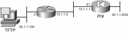
| 4. | Load the npdisk image in the root directory of the TFTP server.
| 5. | From the ROM monitor mode of PIX firewall, configure the network parameters for the interface where the TFTP server is connected. For example, if the ethernet1 interface is connected to the TFTP server, the configuration should like the following (based on Figure 3-3):
Use BREAK or ESC to interrupt boot. Use SPACE to begin boot immediately. Boot interrupted. Use ? for help. monitor> interface 1 monitor> address 10.1.1.1 monitor> file np63.bin monitor> gateway 10.1.1.2 monitor> server 20.1.1.100
| | | 6. | Initiate the TFTP download of the npdisk image.
At this stage, you can initiate the download process for npdisk image. If the password recovery is allowed as per configuration, you will see the following output:
monitor> tftp tftp np63.bin@20.1.1.100 via 10.1.1.2............ Received 92180 bytes Do you wish to erase the passwords? [yn] y The following lines will be removed from the configuration: enable password 8Ry2YjIyt7RRXU24 encrypted passwd 2KFQnbNIdI.2KYOU encrypted aaa authentication serial console LOCAL aaa authentication telnet console LOCAL aaa authentication ssh console LOCAL aaa authentication enable console LOCAL Do you want to remove the commands listed above from the configuration? [yn] y Passwords and aaa commands have been erased. Rebooting..
When npdisk is loaded via the monitor mode, npdisk will read the startup-config file. If service password-recovery is present in the configuration, it will operate as it does in previous versionsit will remove only the startup-config lines that are used to configure the enable password, as in the above output.
If no service password-recovery is configured on the PIX firewall, the following sequence will occur:
[View full width] monitor> tftp ! Following is what's shown when you no password recovery option is configured. Cisco Secure PIX Firewall password tool (3.0) #3: Wed May 5 16:20:53 EDT 2004 . . . . . Using the default startup configuration WARNING: Password recovery has been disabled by your security policy. Choosing YES below will cause ALL configurations, passwords, images, and files systems to be erased and a new image must be downloaded via monitor mode. Erase all file systems? y/n [n]: ! Answering 'yes' to this question will result in a prompt to verify ! deletion and overwriting of all local file systems (flash: for PIX ! platforms). After all file systems are erased the system will reboot ! and a new image must be downloaded via monitor mode. WARNING: Password recovery has been disabled by your security policy. Choosing YES below will cause ALL configurations, passwords, images, and files systems to be erased and a new image must be downloaded via monitor mode. Erase all file systems? y/n [n]: yes Permanently erase flash:? y/n [n]: yes Erasing Flash: ............................... Rebooting... ! Answering 'no' to the question above will result in the system rebooting and ! loading the image on flash: WARNING: Password recovery has been disabled by your security policy. Choosing YES below will cause ALL configurations, passwords, images, and files systems to be erased and a new image must be downloaded via monitor mode. Erase all file systems? y/n [n]: no Rebooting...
When you have password recovery option disabled, when npdisk is loaded, it will detect no service password-recovery in the startup-config file. Hence, the user will be prompted to erase the Flash file system. If the user chooses not to erase the Flash, the system will reload. This is because password recovery depends on maintaining the existing configuration; this erasure prevents you from recovering a password. However, if you choose Yes, the configuration will be removed and you will need to load a new image.
|
Software Upgrade and Downgrade Issues Before proceeding with the upgrade to PIX Firewall Version 7.x, it's important to understand the minimum requirements in terms of hardware, software and the memory. Also it's important to understand different types of releases, which are as follows: Major Feature Releases Major feature releases contain, of course, all the new major features. Typically these releases are not frequent. PIX Firewall Versions 6.0(1), 6.1(1), 6.2(1), 6.3(1), and 7.0(1) are examples of major releases. Maintenance Releases Maintenance releases introduce minor features of PIX Firewall. PIX Versions 6.0(2), 6.0(3), and 6.0(4) are examples of maintenance releases. Also, bugs are fixed in maintenance releases, which are published on the Cisco web site more frequently than the major releases. In addition, the maintenance release features are combined to form the next major release. Interim Releases Interim releases are for bug fixes. All the interim releases, along with additional new minor features, are combined to form the next maintenance release. Examples of interim releases are 6.0(2.100), 6.0(2.101), and 6.0(2.122).
Once you become comfortable with the release process, quickly go through the following list to understand the minimum hardware, software, memory, and flash requirement: Minimum hardware Requirements PIX Version 7.0 software can be upgraded on PIX 515/515E, PIX 525, and PIX 535 platforms. This version is not currently supported on PIX 501 or PIX 506/506E platforms. Minimum software Requirements You must be running Version 6.2 or later to upgrade to PIX Version 7.0. So, if you are running a PIX version earlier than 6.2, you must first upgrade to PIX Version 6.2 or PIX Version 6.3 before you can proceed with the upgrade. Minimum Memory Requirements To upgrade the PIX 515 or PIX 515E, you need to upgrade the memory before performing an upgrade. The PIX 515 and PIX 515E memory upgrades do not require a BIOS update. The minimum flash memory requirement is 16 MB. The memory requirement is based on the types of licenses you have on the PIX as shown in Table 3-8. Table 3-8. Memory Requirements Based On License on PIX 515 and PIX 515ERestricted License | Unrestricted License |
|---|
64 MBAdd an additional 32 MB module to your current 32 MB | 128 MBRemove your two 32 MB modules and install a single 128 MB module |
Note For PIX 515 and PIX 535 platforms that use 8 MB of Flash memory on versions earlier than PIX Version 7.0, the Flash size automatically expands to 16 MB when upgrading to PIX Version 7.0, which is sufficient for PIX Version 7.0 operation. However, you need to perform the upgrade from ROM Monitor mode.
Minimum connectivity requirements The minimum connectivity requirements to perform an upgrade to PIX Version 7.0 are: - A PC that is connected to any network port of the PIX and is running TFTP software. (Your PC can be connected to the PIX using a switch or a crossover cable). - A console connectivity program to talk to the PIX (HyperTerminal or another Terminal Emulation program, DB-9 connector, and rollover cable).
Depending on the platform, you can upgrade the PIX firewall in one of the two following ways: Standard Upgrade Procedure You can a use standard upgrade procedure for any model of PIX other than PIX 515 (not PIX 515E), and PIX 535 to upgrade the PIX from 6.x to 7.x. 1. | Ensure the IP connectivity between the PIX and the TFTP server with the ping command:
PIX# ping 20.1.1.100
Replace 192.168.2.200 with your TFTP server IP address.
| 2. | Save the current configuration with the write net <ip address> <file name> command to the TFTP server.
PIX# write net 20.1.1.100:pix63config.txt
| 3. | Copy the PIX Firewall binary image (for example, pix702.bin) to the root directory of the TFTP server.
| | | 4. | Execute the following command to initiate the upgrade process:
PIX# copy tftp flash:image
| 5. | Enter the IP Address of the TFTP server at the following prompt:
Address or name of remote host [0.0.0.0]? <tftp_server_ip_address>
| 6. | Enter the name of the file on the TFTP server that you wish to load. This will be the PIX binary image file name.
Source file name [cdisk]? <filename>
| 7. | Type yes when prompted to start the TFTP copy.
copying tftp://172.18.173.123/pix701.bin to flash:image [yes | no | again]? yes
The image will now be copied over from the TFTP server to Flash. You should see the following messages indicating that the transfer was successful, the old binary image in Flash is being erased, and the new image is written and installed.
!!!!!!!!!!!!!!!!!!!!!!!!!!!!!!!!!!!!!!!!!!!!!!!!!!!!!!!!!!!!! Received 5124096 bytes Erasing current image Writing 5066808 bytes of image !!!!!!!!!!!!!!!!!!!!!!!!!!!!!!!!!!!!!!!!!!!!!!!!!!!!!!!!!!!!! Image installed PIX#
| 8. | Check and set the correct boot variable.
After copying the file to Flash, confirm the configuration boot command with the following command:
PIX# show running-config | grep boot boot system flash:/pix701.bin PIX#
If the boot system is pointing to the correct file, execute the write memory command to retain this configuration.
PIX# write memory
The correct <filename> is the name of the file on Flash that was copied from the TFTP server earlier. It should show something like boot system flash:/<filename>.
| 9. | If boot system file is set up incorrectly, remove and set this up in the configuration mode:
PIX# configure terminal PIX(config)# no boot system flash:pix701.bin PIX(config)# boot system flash:pix.702.bin PIX(config)# exit PIX# write memory
| | | 10. | Reload PIX Firewall to boot the new image.
PIX# reload Proceed with reload? [confirm] <enter> Rebooting....
The PIX will now boot the 7.0 image.
|
Upgrade using ROM Monitor Mode If you try to upgrade PIX 515 (not PIX 515E) and PIX 535 from Version 6.3 to 7.0, you might run into a problem with the Flash as shown in Example 3-15. The problem is that PIX Version 6.3 can access only 8 MB of onboard Flash out of 16 MB Flash under normal mode of operation. This means that if you have PIX 515 and 535 that have a PDM images installed, you will not be able to upgrade via "copy tftp flash", because there is not enough available space in Flash. You must copy the image over from Monitor mode, and then boot up into 7.0, which will convert the file system, and then you will have to copy the same 7.0 image over again to save it in Flash. If you attempt to upgrade via "copy tftp flash", you will receive the following error: Example 3-15. Insufficient flash PIX# copy tftp://20.1.1.100/cdisk flash: copying tftp://20.1.1.100/cdisk to flash:image !!!!!!!!!!!!!!!!!!!!!!!!!!!!!!!!!!!!!!!!!!!!!!!!!!!!!!!!!!!!!!!!!!!!!!!!!!!!!!!!!! !!!! ! Output is suppressed !!!!!!!!!!!! Received 4902912 bytes Erasing current image ! Insufficient flash space available for this request: Size info:request:4849720 current:1941560 delta:2908160 free:1310720 Image not installed PIX#
|
Work through the following steps to upgrade the PIX firewall to Version 7.0 from ROM Monitor mode on PIX 515 and PIX 535: 1. | Download the PIX 7.x image from the following location and copy it to the root directory of the TFTP server: http://www.cisco.com/cgi-bin/tablebuild.pl/pix
| | | 2. | Enter into Monitor Mode.
Work through the following steps to enter into the Monitor mode:
- a. Connect a console cable to the console port on the PIX using the following communication settings:
9600 bits per second 8 data bits no parity 1 stop bit no flow control
- b. Power cycle or reload the PIX. During bootup you will be prompted to use BREAK or ESC to interrupt Flash boot. You have 10 seconds to interrupt the normal boot process.
- c. Press the ESC key or send a BREAK character to enter monitor mode. If you are using Windows Hyper Terminal, you can press the ESC key or send a BREAK character by pressing Ctrl+Break. If you are telnetting through a terminal server to access the console port of the PIX, you will need to press Ctrl+] (Control + Right bracket) to get to the Telnet command prompt. Then enter the send break command.
- d. This will bring the monitor mode with the monitor> prompt.
- e. Define interface settings in the ROM Monitor mode.
Enter the interface number that the TFTP server is connected to. The default is interface 1 (Inside).
monitor> interface <num>
The command to use the inside interface should look like the following:
monitor> interface 1
Remember that in Monitor Mode, the interface will always auto-negotiate the speed and duplex. The interface settings cannot be hard-coded. Therefore, if the PIX interface is plugged into a switch that is hard-coded for speed and duplex, you must reconfigure it to auto-negotiate while you are in Monitor Mode. Also be aware that the PIX firewall cannot initialize a Gigabit Ethernet interface from Monitor Mode. You must use a Fast Ethernet interface instead.
Enter the IP address of the interface just defined with the following command:
monitor> address <PIX_ip_address>
To assign IP address 10.1.1.1, use the following command:
monitor> address 10.1.1.1
| 3. | (Optional) Enter the IP address of your gateway. A gateway address is required if the PIX's interface is not on the same network as the TFTP server.
monitor> gateway <gateway_ip_address>
If your TFTP server is on a different network (for example, the 172.16.171.0/24 network) define the default gateway so that you know how to get there.
monitor> gateway 10.1.1.100
| | | 4. | Enter the IP Address of the TFTP server with the following command:
monitor> server <tftp_server_ip_address>
If the TFTP server IP address is 172.16.171.1, configure the following:
monitor> server 172.16.171.50
| 5. | Enter the name of the file on the TFTP server that you wish to load. This will be the PIX binary image file name.
monitor> file <filename>
For example, if you are trying to install Version pix702.bin, your configuration will look like this:
Monitor> file pix702.bin
| 6. | Verify IP connectivity by pinging from the PIX to the TFTP server. If the pings fail, double-check the cables, IP address of the PIX interface, and the TFTP server, and the IP address of the gateway (if needed). The pings must succeed before continuing.
monitor> ping <tftp_server_ip_address>
For example, if you have the TFTP server with IP address 20.0.0.101, you can ping as follows:
monitor> ping 172.16.171.50 Sending 5, 100-byte 0xc56 ICMP Echoes to 20.0.0.101, timeout is 4 sec !!!!! Success rate is 100 percent (5/5) monitor>
| 7. | Start the TFTP download by typing "tftp" as follows:
monitor> tftp
The PIX will download the image into RAM and will automatically boot it. During the boot process, the file system will be converted along with your existing configuration. However, you are not finished yet. Note the following warning message after booting.
************************************************************************ ** ** ** *** WARNING *** WARNING *** WARNING *** WARNING *** WARNING *** ** ** ** ** ----> Current image running from RAM only! <---- ** ** ** ** When the PIX was upgraded in Monitor mode the boot image was not ** ** written to Flash. Please issue "copy tftp: flash:" to load and ** ** save a bootable image to Flash. Failure to do so will result in ** ** a boot loop the next time the PIX is reloaded. ** ** ** ************************************************************************
After the image has been copied, wait for the PIX to return to the normal prompt. (This may take from 3 minutes on a PIX 525 to 10 minutes on a PIX 515.)
| | | 8. | Once booted, you enter enable mode and copy the same image over to the PIX again, but this time using the copy tftp flash command. This will save the image into the Flash file system. Failure to perform this step will result in a boot loop the next time the PIX is reloaded.
PIX> enable PIX# configure terminal PIX(config)# interface ethernet 1 PIX(config-if)# ip address 10.1.1.1 255.255.255.0 PIX(config-if)# exit PIX(config)# exit
Use the following command to upgrade the PIX with the following command:
copy tftp[:[[//location] [/tftp_pathname]]] flash[:[image | pdm]]
The following command will show the upgrade procedure:
PIX# copy tftp://20.0.0.101/cdisk.7.0.80.245 flash: Address or name of remote host [20.0.0.101]? Source filename [cdisk.7.0.80.245]? Destination filename [cdisk.7.0.80.245]?
| 9. | Once the image is copied over using the copy tftp: flash: command, the upgrade process is complete.
| 10. | Execute the following command to verify that the image file is loaded in Flash:
PIX# show flash Directory of flash:/ -rw- 2024 05:31:23 Apr 23 2004 downgrade.cfg -rw- 4644864 06:13:53 Apr 22 2004 cdisk.7.0.80.245
| 11. | Set the boot system flash:/ command with the following command:
PIX# configure terminal ! In this case "boot system flash:cdisk.7.0.80.245" to boot from the new image. PIX(config)# boot system flash:/cdisk.7.0.80.245 ! Enter the write memory command to update the flash configuration file. PIX(config)# write memory
| 12. | Enter the reload command:
PIX(config)# reload
| 13. | Execute the show version command and make sure the new version is shown in Flash.
|
Downgrade Procedure To downgrade PIX from Version 7.x to Version 6.x, use the downgrade command instead of the copy tftp flash command. Failure to use the downgrade command will cause the PIX to go into a boot loop. When the PIX is upgraded from 6.x to 7.x, the 6.x startup configuration is saved in Flash with the file name downgrade.cfg. This configuration can be reviewed before downgrade by issuing the command more flash:downgrade.cfg from an enable prompt in 7.0. When you follow the downgrade procedure, which is outlined in the steps that follow, this configuration will be restored to the device when it is downgraded. Additionally, if the PIX is upgraded via Monitor Mode, the previous 6.x binary image will be saved in Flash as image_old.bin. You can verify that this image exists by issuing the show flash: command on 7.0. If the image exists on Flash, you can use this image, instead of loading the image from a TFTP server. Work through the following steps to downgrade the version from 7.x to 6.x on the PIX firewall: 1. | Enter the downgrade command and specify the location of the image that you want to downgrade to.
PIX# downgrade tftp://<tftp_server_ip_address>/<filename>
For example, to downgrade to Version 6.3.4 from TFTP server, execute the following command:
PIX# downgrade tftp://10.1.1.50/pix634.bin
If you upgraded your PIX from Monitor Mode, the old binary image is still saved in Flash. Use the following command to downgrade back to that image:
PIX# downgrade flash:/image_old.bin
| 2. | A Warning message appears alerting you that the Flash is about to be formatted. Press enter to continue.
This command will reformat the flash and automatically reboot the system. Do you wish to continue? [confirm] <enter>
The image will now be copied over into RAM, and the startup configuration is also copied into RAM.
Buffering image !!!!!!!!!!!!!!!!!!!!!!!!!!!!!!!!!!!!!!!!!!!!!!!!!!!!!!!!!!!!!!!!!!! !!!!!!!!!!!!!!!!!!!!!!!!!!!!!!!!!!!!!!!!!!!!!!!!!!!!!!!!!!!!!!!!!!! Buffering startup config All items have been buffered successfully.
| | | 3. | A second warning message appears indicating that the Flash will now be formatted. Do NOT interrupt this process or the Flash may become corrupt. Press enter to continue with the format.
If the flash reformat is interrupted or fails, data in flash will be lost and the system might drop to monitor mode. Do you wish to continue? [confirm] <enter>
The Flash is now formatted and the old image installed, and the PIX is rebooted.
Acquiring exclusive access to flash Installing the correct file system for the image and saving the buffered data !!!!!!!!!!!!!!!!!!!!!!!!!!!!!!!!!!!!!!!!!!!!!!!!!!!!!!!!!!!!!!!!!!!!! !!!!!!!!!!!!!!!!!!!!!!!!!!!!!!!!!!!!!!!!!!!!!!!!!!!!!!!!!!!!!!!!!!!!! Flash downgrade succeeded Rebooting....
| 4. | The PIX will now boot up to the normal prompt.
|
Upgrading PIX Firewall in a Failover Setup Upgrading the PIX Appliance from 6.x to 7.x is a major upgrade. It cannot be accomplished without downtime, even for PIXen in a failover set. Note that many of the failover commands change with the upgrade. The recommend upgrade path is to power down one of the PIXen in the failover set. Then follow the preceding instructions to upgrade the powered-on PIX. Once the upgrade is complete, verify that traffic is passing, and also reboot the PIX once to verify it comes back up without issue. Once you are satisfied that everything is working properly, power off the newly upgraded PIX and power on the other PIX. Then follow the instructions above to upgrade the PIX. Once the upgrade is complete, verify that traffic is passing, and also reboot the PIX once to verify that it comes back up without issue. Once you are satisfied that everything is working properly, power on the other PIX. Both PIXen should now be upgraded to 7.0 and powered on. Verify that they establish failover communications properly by issuing the show failover command. Note The PIX now enforces the restriction that any interface passing data traffic cannot also be used as the LAN failover interface, or the stateful failover interface. If your current PIX configuration has a shared interface that is being used to pass normal data traffic and the LAN failover information or the stateful information, then if you upgrade, the data traffic will no longer pass through this interface. All commands associated with that interface also will fail.
From PIX 6.x to 7.x upgrade, you require a minimum downtime of the network because of the incompatibility between different image versions. From 7.0 to 7.0x, you can upgrade without downtime if the stateful failover is configured. Connection Issues Across PIX Firewall Figure 3-4 shows a typical deployment of the PIX firewall in the network. Figure 3-4. A Typical PIX Firewall Deployment in the Network 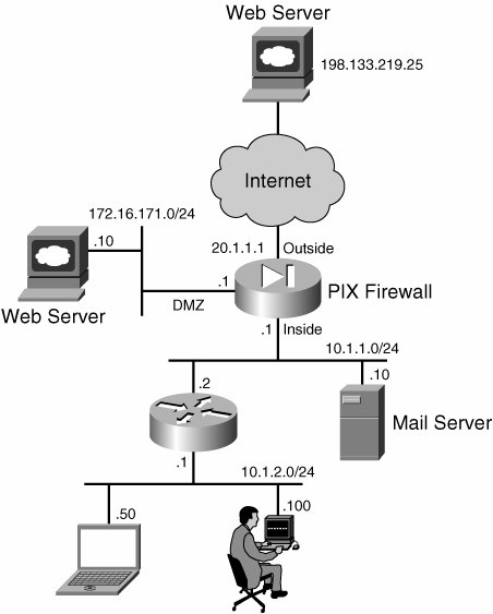
This section discusses the configuration and the troubleshooting steps of the firewall configuration based on Figure 3-4. Configuration Steps Connections initiated from higher security going to lower security (for example, inside to Internet or inside to DMZ interface) are considered to be outbound connections. And the traffic from the lower- to higher-security interface network is considered to be inbound traffic. Work through the following steps to configure PIX Firewall for inbound and outbound traffic: | | 1. | Configure access-list on ingress (incoming) interface (optional).
By default, outbound connections are allowed through the PIX firewall if you have the proper translation (if nat-control is turned on) and the routing configured. If nat-control is turned off, you do not need any translation. However, if you prefer to create an ACL and apply it on the ingress (incoming) interface, be sure to allow the initial traffic so that translation (if nat-control is turned on and NAT is configured for the traffic) and connections can be created on the PIX firewall. This translation and connection information is maintained on the PIX firewall. To allow the outbound web traffic only from the inside network to a single web server IP address 198.133.219.25 (see Figure 3-4), use the following command:
PIX (config) # access-list 101 permit tcp any host 198.133.219.25 eq www PIX (config) # access-group 101 in interface inside
By default, inbound connections are denied on the interface. You must configure an access-list to allow the connection on the interface. However, you must be sure to allow the initial traffic so that translation and connections can be created on the PIX firewall and the state information is maintained. The following ACL will allow SMTP traffic to the mail server (10.1.1.10), which has translated IP address 20.1.1.10:
PIX (config) # access-list 102 permit tcp any host 20.1.1.10 eq smtp PIX (config) # access-group 102 in interface outside
If you want to allow the connection from the web server (172.16.171.10) to the mail server on the inside with the IP address of 10.1.1.10, use the following ACL:
PIX (config)# access-list 103 permit tcp host 172.16.171.10 host 10.1.1.10 eq smtp PIX (config)# access-group 103 in interface dmz
| 2. | Configure for translation or no translation.
Beginning with PIX Firewall Version 7.0, you have the option to turn NAT on or off with the NAT-control command. If the NAT-control command is turned on (off is default unless the PIX is upgraded from 6.3), PIX Firewall requires you to configure the NAT for source address translation by default for outbound traffic, and destination address translation for the inbound traffic. If NAT-control is turned off, NAT will be performed only if the packet matches the source or destination NAT rules.
| | | 3. | Configure NAT for the outbound connection.
There are many options available to configure source address translation depending on your need for the outbound connection.
To configure Dynamic NAT, use the following command:
PIX(config)# global (outside) 1 20.1.1.2020.1.1.50 netmask 255.255.255.0 PIX(config)# global (outside) 1 20.1.1.51 PIX(config)# nat (inside) 1 10.10.1.0 255.255.255.0 PIX(config)# nat (inside) 1 10.10.2.0 255.255.255.0
For outbound connection, you can also configure Dynamic PAT with the interface IP address as follows:
PIX(config)# global (outside) 1 interface PIX(config)# nat (inside) 1 10.10.1.0 255.255.255.0 PIX(config)# nat (inside) 1 10.10.2.0 255.255.255.0
To configure policy NAT for outbound connection, use the following command:
PIX(config)# access-list 101 permit 10.1.1.0 255.255.255.0 any PIX(config)# access-list 101 permit 10.1.2.0 255.255.255.0 any PIX(config)# nat (inside) 1 access-list 101 PIX(config)# global (outside) 1 20.1.1.2020.1.1.50 netmask 255.255.255.0
To configure Policy PAT, use the following commands:
PIX(config)# access-list 101 permit 10.1.1.0 255.255.255.0 any PIX(config)# access-list 101 permit 10.1.2.0 255.255.255.0 any PIX(config)# nat (inside) 1 access-list 101 PIX(config)# global (outside) 1 interface
To use static for the source address translation, use the following command:
PIX(config)# static (inside,outside) 20.1.1.100 10.1.1.100 netmask 255.255.255.255
Note that the same static translation can be used for the inbound connection to the 10.1.1.100 address which has external IP address 20.1.1.100.
If you do not want to perform the NAT for the source address, you can configure identity NAT, which is also known as nat 0 with the following command:
PIX(config)# nat(inside) 0 10.1.1.0 255.255.255.0 PIX(config)# nat(inside) 0 10.1.2.0 255.255.255.0
The same can be configured with the following command:
PIX(config)# access-list 101 permit 10.1.1.0 255.255.255.0 any PIX(config)# access-list 101 permit 10.1.2.0 255.255.255.0 any PIX(config)# nat (inside) 0 access-list 101
The difference between the nat 0 ACL vs. nat 0 network is that with nat 0 ACL, the translation will be bypassed for both inbound and outbound connections. For inbound connections, the destination address will be bypassed and for outbound connections, the source address will be bypassed. But when you have nat 0 network statement, only the source address translation will be bypassed.
| | | 4. | Configure NAT for inbound connection if required.
For an inbound connection you must configure PIX to perform destination address translation. This usually is accomplished with the static command on the PIX firewall as follows:
PIX(config) # static(inside,outside) 20.1.1.100 10.1.1.100 netmask 255.255.255.255
You must allow the traffic to 20.1.1.100 on the outside interface of the PIX for the inbound connection.
To use the interface IP address for the inside host address 20.1.1.100, configure static PAT with the following command:
PIX(config)# static (inside,outside) tcp interface 80 10.1.1.100 80 netmask 255.255.255.255
On the ACL applied to the ingress interface, you must create an ACL to allow the traffic to the 20.1.1.1 address for the web access.
To configure policy static NAT to define additional criteria for the NAT to be triggered for the destination address translation, use the following command:
PIX(config)# access-list 101 permit tcp host 10.1.1.100 eq 80 host any PIX(config)# static (inside, outside) 20.1.1.100 access-list 101
You also can configure bi-directional NAT on the PIX firewall. The details of bi-directional NAT are beyond the scope of this book.
| 5. | Configure routes for outside and inside networks.
You can configure static or dynamic routing protocol on the PIX to populate the routing table. Usually, if PIX performs the NAT/PAT for the Internet-bound traffic, a default gateway is configured to point to the next-hop router. You can have a single default gateway on the PIX firewall. The following command will configure the default gateway for the Internet-bound traffic:
PIX(config)# route outside 0.0.0.0 0.0.0.0 20.1.1.10
As the network 10.1.2.0/24 network is not directly connected to the PIX firewall, but off the inside router, you must configure the following route pointing to 10.1.1.2.
PIX(config)# route inside 10.1.2.0 255.255.255.0 10.1.1.2
You also must have a default gateway on the inside router to point to PIX inside interface IP address (10.1.1.1).
| 6. | Turn on protocol inspection.
By default, several protocol inspections are enabled, which are sufficient to process traffic across the PIX firewall. If there is a protocol that is not inspected, you might need to turn it on.
|
Troubleshooting Steps Before delving into the details of how to troubleshoot connectivity problems, it is important to understand the meaning of different connection flags to quickly identify the problem with connections. You can use combinations of show, debug, and the syslog message that are discussed in this section, to troubleshoot connectivity problems. Figure 3-5 shows the connection flags for both inbound and outbound connections across the PIX firewall for TCP connections. Figure 3-5. PIX Firewall Connection Flags Information for Both Inbound and Outbound Connections 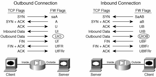
The following numbered steps show the sequence of the packets and the connections flags for the outbound connection (see Figure 3-5) through the PIX firewall: 1. | When PIX receives an initial SYN packet from the inside network, the SYN packet is permitted by the access-list on the ingress interface, a translation (xlate) is built up (if NAT is configured), and the connection is created with the flag saA, which can be verified with the show connection command.
| 2. | The outside device responds to the SYN packet with a SYN+ACK. The connection flags are updated to reflect this, and now show A. Again, this information can be verified with show connection command output.
| 3. | The inside device responds to the SYN+ACK with an ACK, and this completes the TCP 3-way handshake. The connection is now considered up (the U flag will be shown with the show connection command).
| 4. | When the outside device sends the first data packet, the connection is updated, and an I is added to the connection flags to indicate that the PIX received inbound data on that connection.
| 5. | Finally, after the inside device sends a data packet, the connection is updated to include the O flag.
|
Understanding the connection flags for the teardown of the connection is very important. Following is the sequence of packets and the corresponding connection flags for the outbound connection: 1. | When PIX receives a FIN packet from the inside, PIX updates the connection flags by adding an f.
| | | 2. | The outside device immediately responds to the FIN packet with a FIN+ACK. The connection flags are updated to reflect this with UfFR flags.
| 3. | The inside device responds to the FIN+ACK with a final ACK, and the PIX tears down the connection. Thus, there are no more connection flags, because the connection no longer exists.
|
The sequence of events that takes place for the inbound connection is similar to that of the outbound connection on the PIX firewall but it has different flags. Details are not discussed here, but refer to Figure 3-5 for a summary of connection flags for the inbound connection. If you have connectivity problems through the PIX firewall, you need to analyze the connection syslog ID, which is in the following form: PIX-6-302014: Teardown TCP connection number for interface_name:real_address/ real_port to interface_name:real_address/real_port duration time bytes number [reason] [(user)]
The reason field is important to understand. Table 3-9 outlines the reasons for connection terminations. Table 3-9. Reasons for Connection TerminationConnection Flags | Meaning |
|---|
Reset-I | Reset was from Inside | Reset-O | Reset was from Outside | TCP FINs | Normal Close Down Sequence | FIN Timeout | Force Termination After 15 Seconds | SYN Timeout | Force Termination After 2 Minutes | Xlate[*] Clear | Command Line Removal | Deny | Terminate by Application Inspection | SYN Control | Back Channel Initiation from Wrong Side | Uauth Deny | Deny by URL Filter | Unknown | Catch All Error |
[*] An xlate is created dynamically when a packet from a high-security-level interface initiates an outbound connection to a lower-security-level interface.
If you cannot make connection across the PIX firewall, the problem might be with the access-list, NAT, routing, and so on. Work through the following steps to correct the connectivity problem: | | 1. | Is the initial packet reaching the PIX firewall?
This is the first and most important step to troubleshoot the connectivity problem across the firewall. You must be sure the PIX is receiving the initial packet on its interface. If ACL is configured on the interface, you can find out if the packet is reaching to the PIX interface by executing the show access-list command. You should see the hit counts incrementing on the show access-list command output. Another way you can verify if the packets are reaching is by executing the show interface command as shown in Example 3-16. You should see that the Input counters are incrementing. The software input queue is an indicator of traffic load, and "No buffers" indicates packet drops, typically due to bursty traffic.
Example 3-16. Interface Statistics of Inside Interface PIX-A# show interface inside Interface Ethernet1 "inside", is up, line protocol is up Hardware is i82559, BW 100 Mbps Auto-Duplex(Full-duplex), Auto-Speed(100 Mbps) MAC address 000d.2807.097a, MTU 1500 IP address 192.168.1.1, subnet mask 255.255.255.0 32 packets input, 2100 bytes, 0 no buffer Received 0 broadcasts, 0 runts, 0 giants 0 input errors, 0 CRC, 0 frame, 0 overrun, 0 ignored, 0 abort 36 packets output, 2304 bytes, 0 underruns 0 output errors, 0 collisions, 0 interface resets 0 babbles, 0 late collisions, 0 deferred 0 lost carrier, 0 no carrier input queue (curr/max blocks): hardware (128/128) software (0/1) output queue (curr/max blocks): hardware (0/1) software (0/1) Received 35 VLAN untagged packets, 1610 bytes Transmitted 36 VLAN untagged packets, 1008 bytes Dropped 0 VLAN untagged packets PIX-A#
|
To see the details of the packet going across or reaching the PIX firewall, run the capture command as shown in the "Diagnostic Commands and Tools" section.
| 2. | Is the initial packet allowed by the ACL?
For outbound connection across the PIX firewall, you do not have to configure an ACL to allow the traffic. By default, all traffic is allowed. However, for the inbound connection, you must configure an ACL to allow the traffic. Execute the show access-list command and be sure that you see that the hit count on ingress interface ACL increases over time. Remember that creating an ACL is not sufficient; you also must apply the ACL on the interface in the proper direction. Execute show running-config access-group command to verify if indeed the access-list is applied to the correct interface.
| | | 3. | Is translation being built up?
If Steps 12 are verified, the next step is to verify if the translation is being built up for the connection (this is mandatory when the nat-control is turned on or when nat-control is turned off but NAT is configured to perform the translation). If the translation is not being built up, first be sure the nat/global is configured correctly. For example, to verify that the nat/global is configured for the outbound connection, execute the following commands:
PIX# show run nat-control PIX# show running-config nat PIX# show running-config global PIX# show running-config static PIX# show run alias
You need to ensure that the NAT identification corresponds to the global identification.
If some hosts are able to connect through the PIX, but some are not, the problem might be that you are running short of addresses from the global pool. To be on the safe side, it is recommended to configure a PAT address along with the NAT pool (when the nat-control is turned on).
To verify that a host is building up translation, use the following command:
[View full width] show xlate [global | local <ip1[-ip2]> [netmask <mask>]] [gport | lport <port1[-port2]>] [debug]
For example, to find out if inside host 10.1.1.70 is building up the translation, execute the following command:
PIX# show xlate local 10.1.1.70 debug NAT from inside:10.1.1.70 to outside:20.1.1.70 flags - idle 0:00:10 timeout 3:00:00 PIX#
For translation issues, the following syslog message will be generated:
[View full width] PIX-3-305005: No translation group found for tcp src inside:10.1.1.70/11039 dst outside :198.133.219.25/80 PIX-3-305006: regular translation creation failed for tcp src inside:10.1.1.70/11040 dst outside:198.133.219.25/80
To find out the translation and connection entry created for a specific host (10.1.1.70), execute the following command:
PIX# show local 10.1.1.70
If the NAT is not working as expected, run the following debug command to get the details of the NAT translation process:
PIX# debug pix process
| 4. | Is the connection being built up?
If the translation is built up, next make sure that the connection is built up. This can be verified with the show conn or show conn detail commands to find the connection flag. The meaning of different connection flags is in Figure 3-5. You also need to analyze the syslog to see why the connection is being reset. Refer to Table 3-9 to find out the meaning of different connection resets. For example, if you see connection reset reason as Reset-I, the inside host is resetting the connection.
| | | 5. | Is routing set up correctly on PIX?
If you see the translation being built up on the PIX but it does not know where to forward the traffic, you must ensure that you have the route set up correctly. For outbound traffic towards the Internet, you must ensure that the default gateway is set up on the outside interface. If the default route is missing to reach to 198.133.219.25 from the inside host 10.1.1.1, you will get the following syslog message:
PIX-6-110001: No route to 198.133.219.25 from 10.1.1.70
Use the following commands to find out if the route indeed exists:
PIX(config)# show route | include 198.133.219.25
In Figure 3-4, if you want the users from network 10.1.2.0/24 to be able to access 198.133.219.25, in addition to a default gateway configured on the outside interface, you must configure a static route pointing to the inside router as follows:
PIX(config)# route inside 10.1.2.0 255.255.255.0 10.1.1.2
| 6. | Is the return traffic coming back to the PIX?
If the global pool or the translated IP address of the initial packet is not part of the same network as the outside interface network of the PIX, the next-hop router will not get the proxy Address Resolution Protocol (ARP) from the PIX. Hence, it is mandatory to create a static route on the next-hop router for the translated network so that the next hop router directs the packets back to the outside interface of the PIX Firewall. For example, in Figure 3-4, if you are using any address on the global pool which is part of network 20.1.1.0/24, you do not need any route defined on the router where the PIX outside interface is connected. This is because, with nat/global, PIX will proxy ARP the MAC address from the global pool to the router that is connected to the outside router. If the global pool is defined with the IP address not part of the outside interface network (20.1.1.0/24), for example, the 30.1.1.0/24 network, you must define a static route on the outside router for network 30.1.1.0/24 pointing to the outside interface (20.1.1.1) of the PIX firewall.
| 7. | Is the router or the PIX ARPing correctly?
If everything else is set up correctly, and you are still unable to make connection across the PIX firewall, execute the show arp command on the PIX to see if the next-hop address has an ARP entry. For example, if you have a default gateway setup pointing to 20.1.1.10, on the PIX you should see an ARP entry for the 20.1.1.10 address. If the ARP entry is built as shown by the show arp command, execute the debug arp command and then execute the clear arp command to see if the ARP is having issues. ARP can be a problem for the next-hop router (especially on the outside router). When you make changes to the global pool, static and so on, it is recommended to clear the ARP on the outside router.
| | | 8. | Packets are dropped by Accelerated Security Path (ASP).
PIX Firewall contains a system for packet inspection, called the Accelerated Security Path (ASP). All packets have to go through the ASP logic, and if any packet violates the logic, that packet will be dropped by the PIX firewall. Sometimes what the ASP considers to be illegitimate packets may be legitimate for you. So it's important to find out what packets the ASP is dropping. This section presents some techniques that you can use to help troubleshoot the problem.
Execute the show asp drop command to find out counter values for the reasons for packet drops by the ASP. Issue the command clear asp drop then show asp drop to get a baseline of the drops so far, then send the traffic that is not making it through the firewall, and then issue show asp drop again, and check which counters are incrementing. Following is a sample output of the show asp drop command.
PIX# show asp drop Frame drop: Flow is denied by access rule 3001 First TCP packet not SYN 3000 Bad TCP flags 30 TCP failed 3 way handshake 51 TCP RST/FIN out of order 71 TCP SEQ in SYN/SYNACK invalid 10 TCP ACK in SYNACK invalid 10 TCP packet SEQ past window 40 TCP RST/SYN in window 60 TCP DUP and has been ACKed 16 DNS Guard id not matched 80 PIX#
To find the details on what packets are dropped by the ASP, turn on capture with the following command:
PIX# capture capture_name type asp-drop drop-code all packet-length 1518
Drop-code can be all or a specific one in the preceding command. However, because you typically don't know why the PIX is dropping the packet, you cannot specify a specific drop-code; therefore you will usually use all as drop-code. You might need to run interface capture in addition to ASP drop capture to troubleshoot ASP drop issues.
Additionally, instead of sending the debug output to the console, redirect it to the logging buffer with the following commands:
PIX(config)# logging list mylist message 711001 PIX(config)# logging buffered mylist PIX(config)# logging debug-trace PIX(config)# debug fixup tcp PIX(config)# debug pix process
|
After going through the preceding steps, you should be able to resolve most of the connectivity problems. However, if you run into a problem with the PIX Firewall version, you might need to engage the Technical Assistance Center (TAC) for further analysis. Transparent Firewall Issues Beginning with PIX Firewall Version 7.0, the transparent firewall feature is supported. This section explains the configuration and troubleshooting steps of transparent firewall on the PIX firewall. Configuration is based on Figure 3-6. Figure 3-6. Transparent Firewall Deployment 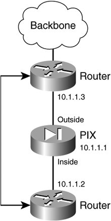
Configuration Steps Work through the following steps to configure transparent firewall based on Figure 3-6: 1. | Turn on transparent firewall.
Convert the PIX firewall with the following command:
PIX(config)# show firewall Firewall mode: Router PIX(config)# firewall transparent Switched to transparent mode PIX(config)#
| 2. | Assign an IP address for management.
Configure the IP address for the PIX firewall for management purposes. This address cannot be used as a default gateway for the host. The IP address should be of the same subnet of the other hosts.
PIX(config)# ip address 10.1.1.1 255.255.255.0
| | | 3. | Configure interfaces (inside and outside).
Bring up both inside and outside interfaces and be sure not to use the IP addresses on the interface. The following command will turn on the outside interface:
PIX(config)# interface Ethernet 0 PIX(config-if)# nameif outside PIX(config-if)# security-level 0 PIX(config-if)# no shutdown
Configure the inside interface with the following commands:
PIX(config)# interface Ethernet 1 PIX(config-if)# nameif inside PIX(config-if)# security-level 100 PIX(config-if)# no shutdown
| 4. | Configure an access-list (optional).
You can configure an access-list optionally, and filter the traffic. The command syntax is as follows:
[View full width] PIX(config)# [no] access-list <acl-name> ethertype <permit | deny> <ether-value> [unicast | multicast | broadcast]
For example, if you want to allow only the IPX traffic, and deny the rest, your ACL configuration will be the like the following:
PIX(config)# access-list 100 ethertype permit ipx
Then, you need to apply the access-list on the interface. If the access-list 100 needs to be applied on the inside interface, the configuration will look like this:
PIX(config)# access-group 100 in interface inside
| | | 5. | Configure ARP inspection.
ARP inspection is turned off by default, which means that all ARP packets are allowed through the PIX firewall. You can control the flow of ARP packets by enabling ARP inspection. When you enable ARP inspection, PIX Firewall compares the MAC address, IP address, and source interface in all ARP packets to static entries in the ARP table, and takes the actions as follows:
- a. If the IP address, MAC address, and source interface match an ARP entry, the packet is allowed through.
- b. If there is a mismatch between the MAC address, the IP address, or the interface, the PIX firewall drops the packet.
- c. If the ARP packet does not match any entries in the static ARP table, you can set the PIX firewall to either forward the packet out all interfaces (flood), or to drop the packet.
ARP inspection prevents network devices from ARP spoofing. ARP spoofing can lead an attacker to a man-in-the-middle attack. For example, a host sends an ARP request to the gateway router; the gateway router responds with the gateway router MAC address. The attacker, however, sends another ARP response to the host with the attacker's MAC address instead of the router's MAC address. The host, thinking that the hacker's MAC address is the valid destination, starts forwarding the packet. The attacker can now intercept all the host traffic before forwarding it on to the router.
ARP inspection ensures that an attacker cannot send an ARP response with the attacker MAC address, if the correct MAC address and the associated IP address are in the static ARP table.
Note In multiple context mode, the commands in this chapter can be entered in a security context, but not in the system context. The dedicated management interface, if present, never floods packets even if this parameter is set to flood. You can add a static ARP Entry with the following command:
arp interface_name ip_address mac_address
ARP inspection compares ARP packets with static ARP entries in the ARP table. The following command allows ARP responses from the router at 10.1.1.1 with the MAC address 0009.7cbe.2100 on the outside interface. Enter the following command.
PIX(config)# arp outside 10.1.1.3 0009.7cbe.2100
Note that the transparent firewall uses dynamic ARP entries in the ARP table for traffic to and from PIX Firewall, such as management traffic. To enable ARP inspection, use the following command:
PIX(config)# arp-inspection interface name enable flood | no-flood]
Here flood forwards non-matching ARP packets out all interfaces, and no-flood drops non-matching packets. Note that the default setting is to flood non-matching packets. To restrict ARP through the PIX firewall to only static entries, set this command to no-flood. The following command enables ARP inspection on the outside interface, and to drop all non-matching ARP Packets.
PIX(config)# arp-inspection outside enable no-flood
To view the current settings for ARP inspection on all interfaces, enter the following command:
PIX(config)# show arp-inspection
| | | 6. | Configure the MAC address table.
Just as with a normal bridge or switch, PIX Firewall learns and builds a MAC address table by inserting the MAC address with the source interface. Unlike a normal bridge or switch, if the destination is not present on the MAC table, PIX does not flood on all interfaces. Instead it does the following:
- a. If the packets are for devices directly connected, PIX firewall generates an ARP request for the destination IP address so that it can learn which interface receives the ARP response.
- b. If the packets for devices are not directly connected, PIX Firewall generates a ping to the destination IP address so that PIX Firewall can learn which interface receives the ping reply. The original packet is dropped.
You can build up the MAC table dynamically or statically. By default, each interface automatically learns the MAC addresses of entering traffic, and PIX Firewall adds corresponding entries to the MAC address table. You can disable MAC address learning if desired; however, unless you add MAC addresses to the table statically, no traffic can pass through the PIX Firewall.
To disable MAC address learning, enter the following command.
PIX(config)# mac-learn interface_name disable
The no form of this command re-enables MAC address learning. The clear configure mac-learn command re-enables MAC address learning on all interfaces.
You can add static MAC addresses to the MAC address table if desired. One benefit to adding static entries is to guard against MAC spoofing. If a client with the same MAC address as a static entry attempts to send traffic to an interface that does not match the static entry, the security appliance drops the traffic and generates a system message.
To add a static MAC address to the MAC address table, enter the following command:
PIX(config)# mac-address-table static interface_name mac_address
The interface name is the source interface. The default timeout value for dynamic MAC address table entries is five minutes, but you can change the timeout. To change the timeout, enter the following command.
PIX(config)# mac-address-table aging-time timeout_value
The timeout_value (in minutes) is between 5 and 720 (12 hours). The default is 5 minutes.
|
Troubleshooting Steps There are a combination of show and debug commands available to troubleshoot problems with transparent firewall. You can determine the mode of firewall with the following command: PIX# show firewall
You can find out the mac-address-table on the PIX in transparent mode with the following command: PIX# show mac-address-table [interface_name]
The following is sample output from the show mac-address-table command that shows the entire table: PIX# show mac-address-table interface mac address type Time Left ----------------------------------------------------------------------- outside 0009.7cbe.2100 static - inside 0010.7cbe.6101 static - inside 0009.7cbe.5101 dynamic 10 PIX#
The following command displays the mac-address-table only for inside interface: PIX# show mac-address-table inside interface mac address type Time Left ----------------------------------------------------------------------- inside 0010.7cbe.6101 static - inside 0009.7cbe.5101 dynamic 10 PIX#
Use the following debug command in addition to the show commands to troubleshoot the transparent firewall issues: debug arp-inspection To track the code path of arp forwarding and arp inspection module in transparent firewall. debug mac-address-table To track insert/delete/update to the bridge table maintained for transparent firewall. debug l2-indication To track code path for processing of layer 2 (l2) indications.
You need to turn on syslog level 4 to see all messages pertaining to transparent problem. This can help in identifying problems pertaining to transparent firewall. MAC Spoofing If you receive a MAC address entry that conflicts with the existing static entry (MAC address to a specific interface), you will get the following syslog message: %PIX-3-321001: Deny MAC address <mac-address>, possible spoof attempt on interface <interface> For example, if you have a static MAC address defined pointing to the DMZ interface, and if you receive the same MAC address dynamically from the inside interface, then it will be considered as MAC spoofing. ARP Inspection If the ARP inspection module drops a packet, the following syslog message will be generated: [View full width] %PIX-3-321002: ARP inspection check failed for arp <request | response> received from host <mac-address> on interface <interface>. This host is advertising MAC Address <mac-address-1> for IP Address <ip-address>, which is currently statically assigned to MAC Address <mac-address-2>.
Host Movement If a MAC address of a host is moved from one interface to the other, the following syslog message will be generated: %PIX-4-411001: MAC <mac-address> moved from <interface-1> to <interface-2> Here interface-1 is the name of the interface from where the host has moved. Interface-2 is the name of the interface to where the host has moved. L2 Table Flooding When the bridge table is full and an attempt is made to add one more entry by the Mac-address of the host, the following syslog message will be generated: [View full width] %PIX-4-411002: Detected bridge table full while inserting MAC <mac-address> on interface <interface>. Number of entries = <num>
Virtual Firewall Beginning with PIX Firewall Version 7.0, you can logically partition a single PIX firewall into multiple logical PIX firewalls. Each logical PIX firewall can have its own security policy and administration control. This logical PIX firewall is called a Security Context, which is discussed next. Security Context Depending on your type of platform and the license, you can have up to 50 security contexts on the PIX, which means you can create up to 50 logical PIXen out of a single PIX firewall. As mentioned before, each security context is an independent firewall with its own security policy, interfaces, and administrators. Almost all the required features to provide the firewalling are possible with multiple contexts: firewall features, IPS, and management, to name a few. Note, however, that with multiple mode some of the features are not supported, including VPN (you can still establish VPN for management purposes only), Web VPN, Dynamic Routing protocols, and Multicast. As soon as you convert the PIX firewall from single to multiple mode, it creates the system resource space and the admin context: System Resource After converting into multiple mode, when you log in to the PIX, you are taken to the System Resource space. From System Resource, the system administrator adds and manages contexts. The System Resource configuration identifies basic settings for the PIX firewall. The system Resource space does not include any network interfaces or network settings for itself; rather, when the system needs to access network resources (such as downloading the contexts from the server), it uses the admin context, which can have interface and network connectivity. Admin Context The admin context is created as soon as you convert the PIX firewall into multiple mode. It is just like any other context, except that users for admin context can access system administrator rights and can access the system and all other contexts. Typically, the admin context provides network access to network-wide resources, such as a syslog server or a context configuration server. User Security Context Apart from the admin context, you can create an individual security context. The limit is up to 50 based on your PIX model. Each security context is just like a single PIX firewall.
How the Virtual Firewall Works When PIX operates in multiple context mode, each packet that enters the PIX firewall must be classified, so that the PIX can determine to which context it should send a packet. This is the job of a component of the PIX software called classifier. To classify the packets, the classifier goes through the following order to check with the destination IP address of the packet: | | 1. | Context Interface IP Address
If the destination address of the packet is the interface IP address of the context (for instance, outside the interface IP address of a context) that means the packet is for a specific context, hence the classifier marks the packet for that context. An example of these types of packets is an SSH connection to a specific context to mange the context.
| 2. | Source Interface (VLAN)
If the destination address of the packet is not one of the interface IP addresses of the context, the next check is performed based on the source VLAN of the packet. For example, if Ethernet 1 and Ethernet 2 interfaces are connected to VLAN100 and VLAN200, respectively, and if these interfaces are mapped to the context 1 and context 2, when the packet enters into PIX through Ethernet 1, the classifier will forward the packet to context 1, which is obvious. To make it little more complex, assume that Ethernet 1 is configured as trunks for VLAN100 and VLAN200, and VLAN100 is mapped to context1 and VLAN200 is mapped to context 2. With this setup, if the packet reaches to the PIX using VLAN 200, the classifier will forward the packet to context 2. Figure 3-7 shows an example to illustrate this point.
Figure 3-7. Source VLAN Varies with Multiple Contexts 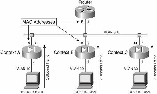
This example shows VLAN 10, 20, and 30 mapped to separate contexts, so for outbound traffic; the classification will be made based on these sources' VLAN. Note that the PIX inside interface can be configured as a trunk for these VLANs, and then mapped to the individual VLAN to the respective contexts. For example, VLAN 10 should be mapped to Context A. For return traffic, the classifier would already know which context the return traffic belongs to. Even though the outside VLAN 500 is shared for the outside interface across all three contexts, the classifier builds up the knowledge base on which context the return packet should belong to based on the source address translation of the initial outbound traffic.
| | | 3. | Destination Address
If the packet is not destined for the interface IP address of any context, and if the source VLAN of the packet is shared as shown in Figure 3-8 for the inbound connection, the classifier makes the decision on which context the packet needs to be forwarded based on the destination IP address.
Figure 3-8. VLAN Sharing with Multiple Contexts 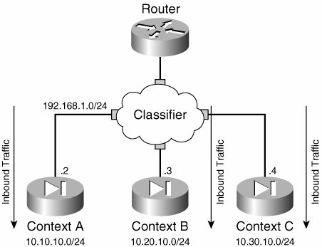
Therefore, PIX classifier needs to have the knowledge of the destination network for each context. The classifier learns this destination network based on the translation configured on the contexts. Figure 3-8 illustrates this point.
|
For inbound traffic initiated from outside, the classifier looks only at static statements where the global interface matches the source interface of the packet. So in Figure 3-6, to allow the inbound connection initiated from outside, configure static NAT on each classifier for the inside network. Limitations of Virtual Firewall Before delving into the details of configuration and troubleshooting of Virtual Firewall, it is important to understand some of the limitations of the Firewall implementation: Transparent Firewall in Multiple Contexts In routed mode, the classifier classifies the packet based on source VLAN, or destination IP address. So it is possible to share the same VLAN across multiple contexts with the help of NAT. But, in transparent mode, NAT cannot be configured. Therefore, classification is based only on source VLAN. This means it is not possible to share the same VLAN across multiple contexts. NAT Zero Access List and Shared Interfaces in routed mode On the PIX Firewall, you can configure "NAT zero access-list" to bypass the NAT for the traffic defined on the ACL. If you do that and if the VLAN is shared, the classifier will not know the destination address per context, so communication will fail. Hosts on Shared Interfaces Cannot Initiate Outbound Connections If you share the inside VLAN among multiple contexts, this will cause problems, unless you have the destination address translation configured. Usually outbound traffic is Internet-bound, and configuration address translation may not be possible. Therefore, it is strongly recommended not to share the inside VLAN for outbound traffic among multiple contexts.
Configuration Steps Figure 3-9 shows two context deployments of the PIX firewall. Figure 3-9. Two Context Deployment of the PIX Firewall 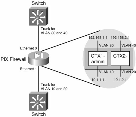
Work through the following steps to configure multiple contexts on the PIX firewall based on Figure 3-9: | | 1. | Change the mode of operation from the single to multiple with the following command:
PIX(config)# mode multiple WARNING: This command will change the behavior of the device WARNING: This command will initiate a Reboot Proceed with change mode? [confirm] Convert the system configuration? [confirm] . . . . . .
Once the PIX is booted up, execute the following show command and be sure that the security context mode is shown as multiple:
PIX# show mode Security context mode: multiple PIX#
After the PIX is converted to the multiple context, once you log in to the PIX, you will be taken to the System Resource Space (context). From here, you can configure the rest of the other contexts. The context admin will be created by default, which can be verified with the following command:
PIX# show running-config context admin context admin config-url flash:/admin.cfg ! PIX#
| 2. | Configure interfaces.
You need to configure all interfaces on the system context before they can be mapped to the user security context. For this setup, the inside and outside (both interfaces) are configured as trunk carrying VLAN 10 and 20 on the inside and VLAN 30 and 40 on the outside. For the outside interface, configure the PIX in the system context as follows:
PIX(config)# interface Ethernet 0 PIX(config-if)# speed auto PIX(config-if)# duplex auto PIX(config)# interface Ethernet 0.30 PIX(config-subif)# vlan 30 PIX(config-subif)# interface Ethernet 0.40 PIX(config-subif)# vlan 40
Similarly, configure the inside interface for VLAN 10 and 20 as follows:
PIX(config)# interface Ethernet 1 PIX(config-if)# speed auto PIX(config-if)# duplex auto PIX(config)# interface Ethernet 1.10 PIX(config-subif)# vlan 10 PIX(config-subif)# interface Ethernet 0.20 PIX(config-subif)# vlan 20 PIX(config-subif)#
| | | 3. | Create contexts.
From system context, you can create a new context or change the role of admin context. To do this, you need to create a new context that you want to designate as admin context. For instance, if you want to configure contexts ctx1 and ctx2, and want to make ctx1 your admin context, you need to create the two new contexts as follows:
PIX(config)# context ctx1 PIX(config-ctx)# config-url flash:/ctx1.cfg PIX(config)# context ctx2 PIX(config-ctx)# config-url flash:/ctx2.cfg PIX(config-ctx)#
Now assign the admin context role to ctx1 context as follows:
PIX(config)# admin-context ctx1
Finally remove the admin context that was created by default as follows:
PIX(config)# no context admin
Verify the contexts you have just created:
PIX# show context Context Name Interfaces URL *ctx1 flash:/ctx1.cfg ctx2 flash:/ctx2.cfg Total active Security Contexts: 2 PIX#
| 4. | Associate interfaces to the contexts.
You need to associate the interfaces from the system context with the allocate-interface commands. For example, to allocate interfaces Ethernet0.30, and Ethernet1.10, you can use the following commands:
PIX(config)# context ctx1 PIX(config-ctx)# allocate-interface Ethernet0.30 PIX(config-ctx)# allocate-interface Ethernet1.10
Similarly, the following interface mappings are for context ctx2:
PIX(config)# context ctx2 PIX(config-ctx)# allocate-interface Ethernet0.40 PIX(config-ctx)# allocate-interface Ethernet1.20
After creation of context, verify it with the following command:
PIX# show context Context Name Interfaces URL *ctx1 Ethernet0.30, Ethernet1.10 flash:/ctx1.cfg ctx2 Ethernet0.40, Ethernet0.20 flash:/ctx2.cfg Total active Security Contexts: 2 PIX#
| | | 5. | Configure the interfaces on the context.
From system context, go to the respective contexts to configure the interfaces with changeto command. The following commands show how to configure the interfaces on the context ctx1:
PIX(config)# changeto context ctx1 PIX/ctx1(config)# interface Ethernet0.30 PIX/ctx1(config-if)# ip address 192.168.1.1 255.255.255.0 PIX/ctx1(config-if)# nameif outside PIX/ctx1(config-if)# exit
The following commands are used to configure the inside interface on context ctx1:
PIX/ctx1(config)# interface Ethernet1.10 PIX/ctx1(config-if)# ip address 10.1.1.1 255.255.255.0 PIX/ctx1(config-if)# nameif inside PIX/ctx1(config-if)# exit
Configure interfaces for context ctx2 in the same way as for context ctx1:
PIX(config)# changeto context ctx2 PIX/ctx2(config)# interface Ethernet0.40 PIX/ctx2(config-if)# ip address 192.168.2.1 255.255.255.0 PIX/ctx2(config-if)# nameif outside PIX/ctx2(config-if)# exit PIX/ctx2(config)# interface Ethernet1.20 PIX/ctx2(config-if)# ip address 10.1.2.1 255.255.255.0 PIX/ctx2(config-if)# nameif inside PIX/ctx2(config-if)# exit
| 6. | At this stage, you can treat both ctx1 and ctx2 contexts as individual firewalls and define the policies, NAT, and so on just as you would do for a regular PIX firewall.
To go back to the system context, execute the following command:
PIX(config-ctx)# changeto context system PIX(config)#
|
Troubleshooting Steps Troubleshooting techniques for multiple contexts are the same as for a single context, so the same information will not be repeated here. Most of the problems that arise with multiple context are caused by a lack of understanding of how multiple context works. It is strongly recommended that you work through the preceding section to understand how multiple context works and how to configure the PIX firewall correctly. Quality of Service (QoS) Issues Beginning with PIX Version 7.0, there are two QoS features available on PIX Firewall: Policing Policing is used to control the amount of traffic that can flow through an interface. On the PIX, policing is supported for outbound traffic only. The example that follows illustrates this concept. Assume that you have a LAN-to-LAN connection between the main office (hub), and a remote office (spoke). The communication between the LAN of the hub, 10.1.1.0/24 and LAN of the spoke, 10.1.2.0/24 is protected by the LAN-to-LAN IPsec tunnel. Assume that you want to limit traffic from the main office to remote office traffic so that the VPN data link does not become oversubscribed. To achieve this, work through the steps that follow to configure outbound policing on the PIX firewall on the main office (hub): Step 1. | Create a class-map to classify the traffic subject for policing.
Use the class-map command to enter class-map configuration mode. From class-map configuration mode, you can define what traffic should be included in the class using the match command.
The following is an example that shows how to classify the VPN traffic (tunnel group name is spoke1) for policing for destination IP address flow:
PIX(config)# class-map remote-VPN-traffic PIX(config-cmap)# match flow ip destination-address PIX(config-cmap)# match tunnel-group spoke1 PIX(config-cmap)#
The following commands are available in class-map configuration mode:
- - description It describes the class-map.
- - match any It specifies all traffic to be matched.
- - match access-list Traffic classification is made based on the access-list.
- - match port It specifies that traffic should be matched using a TCP/UDP destination port.
- - match precedence This specifies that the precedence value represented by the Type of Service (TOS) byte in the IP header should be matched.
- - match dscp It specifies that the Internet Engineering Task Force (IETF)-defined DSCP value in the IP header should be matched.
- - match rtp This specifies that an RTP port should be matched.
- - match tunnel-group It specifies that the security-related tunnel groups should be matched.
- - match flow It specifies that the IP destination address should be matched.
- - Match default-inspection-traffic This specifies that the default traffic for the inspect commands should be matched.
| | | Step 2. | Create a policy-map describing the action you want to perform on the data flow.
To define the policy map, use the following command syntax:
PIX(config)# policy-map mypolicy PIX(config-pmap)# ? MPF policy-map configuration commands: class Policy criteria description Specify policy-map description exit Exit from MPF policy-map configuration mode help Help for MPF policy-map configuration commands no Negate or set default values of a command rename Rename this policy-map <cr> PIX(config-pmap)#
The descriptions of keywords are as follows:
- - class Specifies a class-map for traffic classification.
- - clear configure policy-map Specifies that all policy-map configurations should be removed with one exception: if a policy-map is in use in a service-policy command, that policy-map is not removed.
- - description Specifies a description for the policy-map.
- - help policy The map shows syntax help for the policy-map command.
For your example, if you want to configure police rate 10,000 bps, and burst 15,000 bytes, and if VPN traffic exceeds the burst and then drops, your policy-map can be configured as follows:
PIX(config)# policy-map vpn-Policy PIX(config-pmap)# class remote-VPN-traffic PIX(config-pmap-c)# police 10000 15000 conform-action transmit exceed-action drop
Once the policy-map is configured, you can verify it with the following command:
PIX# show running-config policy-map
| | | Step 3. | Attach the policy map to a service-policy.
The service-policy identifies the interface at which the action is performed.
Use this command to apply the service policy:
PIX(config)# service-policy policy-map-name interface interface-name
For example, to apply a service policy globally, use the following command:
PIX(config)# service-policy global-policy global
To apply the policy on the outside interface, use the following configuration:
PIX(config)# service-policy vpn-Policy interface outside
|
Low Latency Queuing (LLQ) Low Latency Queuing is important for latency-sensitive traffic such as VoIP traffic. If you want to make sure VoIP phones at the main office have the lowest latency possible through the firewall and VPN to the remote office, you need to configure LLQ. To be effective, you must configure LLQ in both directions both on the Main and the Remote sites. Just as with Policing, assume that you have a LAN-to-LAN between the main office (hub), and the remote office (spoke). The communication between the LAN of hub, 10.1.1.0/24 and LAN of spoke, 10.1.2.0/24 is protected by the LAN-to-LAN IPsec tunnel. Assume that you want to apply LLQ for the voice traffic across the tunnel. Work through the following steps to accomplish this task: Step 1. | Create a class-map describing the data flow. More than one class-map is required; one for voice traffic, and other one for the rest of the other traffic.
All voice traffic can be classified with the following class-map, which requires LLQ:
PIX(config)# class-map remote-Voice PIX(config-cmap)# match tunnel-group spoke1 PIX(config-cmap)# match dscp ef PIX(config-cmap)#
The following class-map classifies the rest of the other traffic that doesn't require LLQ:
PIX(config)# class-map remote-Other-traffic PIX(config-cmap)# match tunnel-group spoke1 PIX(config-cmap)# match flow ip destination-address PIX(config-cmap)#
| | | Step 2. | Create a policy-map describing the action on the previously created class-map.
Create a policy-map and apply priority queue for the VOICE traffic and the policing for the other traffic as follows:
PIX(config)# policy-map vpn-Policy PIX(config-pmap)# class remote-Voice PIX(config-pmap-c)# Priority PIX(config-pmap)# class remote-Other-Traffic PIX(config-pmap-c)# police outside 200000 37500 conform-action transmit exceed-action drop
Note You cannot combine priority and police in the same class map. | Step 3. | Attach the policy-map to a new or existing service-policy that identifies where the action is performed.
Bind the policy-map outside-policy to the interface with the following command:
PIX(config)# service-policy vpn-Policy interface outside
| Step 4. | Configure priority queues for LLQ and Best Effort traffic.
Use the following command to configure priority queue on the interface:
priority-queue interface name tx-ring-limit value queue-limit value
Example 3-17 shows a sample of priority queue on the outside interface of the PIX firewall.
Example 3-17. Priority Queue Applied to the Outside Interface PIX(config)# priority-queue outside ! <max allowed no of packets queued at the tx-ring for the priority-queue> PIX(priority-queue)# tx-ring-limit 20 ! <max # of packets queued at the priority queue> PIX(priority-queue)# queue-limit 20 PIX(priority-queue)#
|
|
Troubleshooting Steps Use the show service-policy command to get statistics, and observe their behavior to determine operational status. There is no low latency queue or priority queue in multiple context modes. Performance Issues When you run into high CPU or low memory on the PIX, you might observe one or more of the following symptoms: A packet drops across the firewall. You are unable to log in to PIX either via Telnet, SSH or even the console. You are unable to execute any command on the CLI even if you can connect to it.
This high CPU and low memory condition on the PIX firewall can be caused by normal or abnormal traffic. Examples of abnormal traffic are attacks, worms, viruses, and so on, in the network. However, if you have just deployed a new PIX in the network, and you are having performance issues, you might be reaching the CPU or memory limit on the PIX. This can happen if you have an additional feed or bandwidth increment for your existing PIX. It can also happen because of misconfiguration on the switch that causes the redirecting of all traffic into the port of the PIX firewall. However, if performance deteriorates suddenly, chances are that either you are running into a configuration issue on the PIX or your network is under attack. This section describes troubleshooting steps for isolating issues with CPU and memory problems. High CPU Utilization It is important to keep the CPU utilization under 60 percent. If utilization exceeds 60 percent, you must examine the traffic and see if you need to consider a firewall with higher performance, or if you are under attack. Work through the following steps to identify and correct high CPU utilization problem: | | Step 1. | Find out the summary of CPU utilization.
In both single and multiple mode, execute the following command to obtain the summary of the CPU usage at any time:
PIX# show cpu [usage] [context {all | context_name}]
A sample output of the show cpu usage command is as follows:
PIX# show cpu usage CPU utilization for 5 seconds = 1%; 1 minute: 0%; 5 minutes: 0% PIX#
A sample output of CPU usage for a specific context in multiple context mode follows:
PIX/context_name(config)# show cpu usage context admin CPU utilization for 5 seconds = 1%; 1 minute: 0%; 5 minutes: 0% PIX/context name(config)#
You can find out the same information by executing the command from the context itself as follows:
PIX/context_name(config)# show cpu usage context admin CPU utilization for 5 seconds = 1%; 1 minute: 0%; 5 minutes: 0% PIX/context name(config)#
The following command shows how to display the CPU utilization for all contexts:
PIX(config)# show cpu usage context all CPU utilization for 5 seconds = 1%; 1 minute: 0%; 5 minutes: 0% 5 sec 1 min 5 min Context Name 0% 0% 0% admin 59% 59% 59% system 41% 41% 41% <kernel> PIX#
If the CPU utilization is showing high, move to the next step to find out which process is causing the high CPU utilization.
| Step 2. | Identify the process that is utilizing maximum CPU cycles.
Execute the show process command on the PIX firewall and find out the run time of the process. You should compare the other processes with different poll processes, for example, the 557poll process. Example 3-18 shows that the Logger process is utilizing the maximum CPU cycles other than 557poll.
Example 3-18. Output of show processes on PIX Firewall PIX(config)# show processes PC SP STATE Runtime SBASE Stack Process Hsi 001eab19 008a5a74 00557910 0 008a4aec 3628/4096 arp_timer Lsi 001f00bd 00a28dbc 00557910 0 00a27e44 3832/4096 FragDBGC Lwe 00119abf 02d280dc 0055b070 0 02d27274 3688/4096 dbgtrace Lwe 003e4425 02d2a26c 00557dd8 74440 02d28324 6936/8192 Logger Crd 001e26fb 0533940c 00557d88 6070290 05338484 3684/4096 557poll Lsi 00300a29 04c0f504 00557910 0 04c0e57c 3944/4096 xlate clean .... PIX(config)#
|
As it is not clear how severely CPU cycles are utilized by the Logger process, take a show process command output in one-minute intervals. Now take the difference, and list the difference of CPU utilization as shown in Example 3-19.
Example 3-19. The Differences in CPU Utilization by Different Process Process_Name Runtime (msec) Logger 35340 pix/intf3 28410 557poll 8250 i82543_timer 5180 i82542_timer 2330
|
As you can see, the Logger process is utilizing the maximum CPU cycles. Starting with PIX firewall version 7.0, you can find out the same information just discussed on which process is utilizing the highest CPU cycles by executing show processes cpu-hog. This is preferred to the method that was just explained.
| | | Step 3. | Examine the process and take corrective action.
As the Logger process is using the maximum CPU, review the configuration for syslog as shown in Example 3-20.
Example 3-20. The Output of the show log Command PIX(config)# show log Syslog logging: enabled Standby logging: disabled Console logging: disabled Monitor logging: disabled Buffer logging: level alerts, 0 messages logged ! Following line shows huge amount of trap level logging, which mean this much ! of syslog information is written to the syslog server. But this in total since ! the PIX is rebooted last. Trap logging: level warnings, 6929312 messages logged Logging to inside 172.16.171.10 History logging: disabled . . . PIX(config)#
|
In Example 3-20, it is not conclusive how quickly the PIX is generating so many messages to the syslog. Therefore, execute the show log command again as shown in Example 3-21 and compare the new output with the previously taken output that was shown in Example 3-20.
Example 3-21. The show log Output Taken After a Few Minutes PIX(config)# show log Syslog logging: enabled Buffer logging: level alerts, 0 messages logged !Notice the amount of messages logged after few minutes Trap logging: level warnings, 9152372 messages logged Logging to inside 172.16.171.10 PIX(config)#
|
| | | Step 4. | Investigate the Syslog messages.
At this stage, you should be fairly certain that the syslog is causing the high CPU utilization problem. So you need to determine if it is because of attack or misconfiguration. If the syslog server is available, perform the analysis from the syslog server, or turn on the buffer logging.
For this specific example, assume that the syslog server is down, which will cause the PIX to generate the syslog messages as shown in Example 3-22.
Example 3-22. show log Output When the Syslog Server Is Unreachable PIX(config)# show log Buffer logging: level warnings, 41527 messages logged Trap logging: level warnings, 9553127 messages logged Logging to inside 172.16.171.10 . . . 400011: IDS:2001 ICMP unreachable from 172.16.171.10 to 172.16.171.1 on interface inside 400011: IDS:2001 ICMP unreachable from 172.16.171.10 to 172.16.171.1 on interface inside 400011: IDS:2001 ICMP unreachable from 172.16.171.10 to 172.16.171.1 on interface inside 400011: IDS:2001 ICMP unreachable from 172.16.171.10 to 172.16.171.1 on interface inside 400011: IDS:2001 ICMP unreachable from 172.16.171.10 to 172.16.171.1 on interface inside 400011: IDS:2001 ICMP unreachable from 172.16.171.10 to 172.16.171.1 on interface inside PIX(config)#
|
In the previous example, ICMP Unreachable is generated by the syslog server for each syslog message PIX is sending to the syslog server. The problem is aggravated when the Intrusion Prevention System (IPS) is configured, because for every ICMP unreachable message, PIX is generating an IPS message and sending it to the syslog server, which in turn generates another similar message. And this cycle continues until the syslog server is rechargeable.
To correct the problem, you need to bring up the syslog server or turn off logging. You might consider turning of IPS until the syslog server is up again.
| Step 5. | Follow the same procedure to correct other problems. For example, if you are under attack, examining the syslog along with sniffer capture will assist in finding the hosts that are infected, so that you can correct the problem by patching the host, or, as a temporary work-around, configuring the PIX with ACL to drop the bad packets on the interface. Actions that need to be taken differ depending on the problem.
| Step 6. | Re-examine the CPU output, and repeat as necessary.
|
For additional details on troubleshooting performance issues on the PIX firewall, refer to the following link: http://www.cisco.com/en/US/products/hw/vpndevc/ps2030/products_tech_note09186a008009491c.shtml To find out the function of different processes on the PIX, refer to the following link: http://www.cisco.com/en/US/partner/products/hw/vpndevc/ps2030/products_tech_note09186a008009456c.shtml High Memory Utilization If you cannot make a new connection across the PIX firewall, but your existing connections are working well, most likely you are running into low memory issues. Work through the steps that follow to identify and correct the problem: | | Step 1. | Check the amount of free memory available with the following command:
PIX# show memory Free memory: 40955872 bytes (61%) Used memory: 26152992 bytes (39%) ------------- ---------------- Total memory: 67108864 bytes (100%) PIX#
This output will show the memory available. If free memory is low, investigate the reason for the low memory.
| Step 2. | Analyze the syslog message to find out if you received the following message for running short of memory:
%PIX-3-211001: Memory allocation Error %PIX-3-211001: Memory allocation Error
| Step 3. | Identify what is utilizing the memory (RAM) most heavily on the PIX. Before you can make that identification, you must know how memory is utilized on the PIX. Several things use up memory, such as the PIX image (run from RAM), configuration, the IPsec database, Xlates (translations), and connections. Most of the time, if the problem appears suddenly, the problem is with either translations or connections.
So, you need to check the translations count with the show xlate command as shown below:
PIX# show xlate count 350 in use, 400 most used PIX#
The translation count in this example looks normal.
Now, quickly find the connection count with the following command:
PIX# show conn count 161723 in use, 161723 most used PIX#
So, it appears that with only 350 translations, 16,1723 connections are made, which is an indication that your network may be infected by a virus or worm.
| | | Step 4. | Now analyze the traffic load and find out from which interface the vast majority of traffic is coming. You can find this information with the command shown in Example 3-23.
Example 3-23. Examining Traffic Load with the show traffic Command PIX# show traffic ! Following statistics is for outside interface outside: received (in 50.000 secs): 2170 packets 501050 bytes 65 pkts/sec 21752 bytes/sec transmitted (in 50.000 secs): 187629 packets 9455480 bytes 7601 pkts/sec 394156 bytes/sec ! Following statistics is for outside interface inside: received (in 25.000 secs): 180224 packets 10410480 bytes 7208 pkts/sec 416419 bytes/sec transmitted (in 50.000 secs): 7500 packets 124631 bytes 65 pkts/sec 6725 bytes/sec PIX#
|
As you can see in the previous example, the inside interface is receiving the vast majority of traffic very fast (7208 pkts/sec). So, at this point, you can be fairly certain that a virus or a worm has infected the inside hosts.
| Step 5. | Identify the hosts that are generating all the connections. Example 3-24 shows how to find out the hosts that are generating all these connections:
Example 3-24. Identifying Hosts that Are Generating All These Connections PIX# show local-host | include host|count/limit local host: <10.1.1.10>, TCP connection count/limit = 2/unlimited UDP connection count/limit = 0/unlimited local host: <10.1.1.20>, TCP connection count/limit = 5/unlimited UDP connection count/limit = 0/unlimited local host: <10.1.1.50>, TCP connection count/limit = 12/unlimited UDP connection count/limit = 0/unlimited . . . local host: <10.1.1.100>, TCP connection count/limit = 151501/unlimited UDP connection count/limit = 0/unlimited PIX#
|
The previous example shows that the majority of the traffic is indeed coming from 10.1.1.100.
| | | Step 6. | Now that you have found the host that is generating all this traffic, look at the connections, and find the details of the type of connection as shown in Example 3-25.
Example 3-25. Connections Generated by the Host PIX# show local-host 10.1.1.100 Interface inside: 300 active, 300 maximum active, 0 denied local host: <10.1.1.100>, TCP connection count/limit = 166108/unlimited TCP embryonic count = 166108 UDP connection count/limit = 0/unlimited Xlate(s): Global 209.165.201.21 Local 10.1.1.100 Conn(s): TCP out 65.101.32.157:135 in 10.1.1.100:34580 idle 0:01:43 Bytes 0 flags saA TCP out 65.103.108.191:135 in 10.1.1.100:8688 idle 0:01:43 Bytes 0 flags saA TCP out 65.100.205.160:135 in 10.1.1.100:7774 idle 0:01:43 Bytes 0 flags saA TCP out 65.101.182.19:135 in 10.1.1.100:39193 idle 0:01:43 Bytes 0 flags saA . . . . . . PIX#
|
The preceding example shows that all connections are embryonic connections, which reaffirms that the host is infected.
| Step 7. | To cure the problem, patch the machine, and take any other actions recommended by the anti-virus software vendor. If the patch is not possible immediately, shut down the machine and unplug it from the network.
| Step 8. | As a temporary work-around, you can limit the maximum number of connections for the specific host as follows:
PIX(config)# nat (inside) 1 10.1.1.100 255.255.255.255 50 0
For the remainder of the network, configure for unlimited connections as follows:
PIX(config)# nat (inside) 1 0.0.0.0 0.0.0.0 0 0
Finally, be sure to clear the local host with the following command:
PIX(config)# clear local-host 10.1.1.100
| Step 9. | If the memory is leaked by a specific process, you may run into problem with memory on the PIX firewall even under normal load of traffic. Under this circumstance, use the output of show process memory over time to see which process is continually getting more memory allocated, but not freeing it back. Then look for specific bug on the code.
|
Large ACL ACL comprises multiple Access Controls Elements (ACEs), which are processed sequentially in top-down fashion. So, it is very important that you configure the entries that are most likely to be matched towards the top of the access-list. The performance impact of an access-list increases linearly with the increase in the number of ACEs. So, try to summarize the address ranges of the ACEs as much as possible. The smaller the list is, the less the CPU is used and the shorter the time required to search sequentially for an entry. If you have a huge number of ACEs even after summarization, configure turbo ACL. Note that the turbo ACL feature is available only on PIX Firewall Version 6.2 and above. Reverse DNS & IDENT Protocol If you can connect to the servers but need to wait a long time before the data comes back, you might run into a problem with reverse DNS or IDENTD. To work around the problem with DNS issues, be sure to allow UDP/53 to the DNS server from the destination server, provided that the DNS server is behind the PIX firewall. To get around the problem for IDENT protocol, be sure to allow TCP/113 through the PIX firewall so that the server can communicate with the client on TCP/113. |