| This case study examines the configuration required for shunning on the sensor by IDS/IPS MC based on Figure 18-4. Our assumption is that the IDS/IPS sensor is imported to the IDS/IPS MC and all the connectivity is established among IDS/IPS MC, IDS/IPS sensor, and the routers (managed device). Figure 18-4. Sensor Setup in the Network 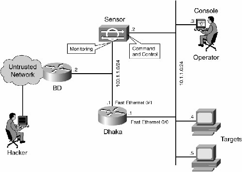
Work through the following procedures to configure shunning. Step 1. | At the VMS server console, select VPN/Security Management Solution > Management Center > IDS/IPS Sensors.
| Step 2. | Select the Configuration tab, select your sensor from Object Selector, and click Settings.
| Step 3. | To add a new signature, select Signatures, click Custom, and then click Add.
| Step 4. | Enter the new Signature Name, and then select the Engine (in this case, STRING.TCP) from the drop-down list.
| Step 5. | You can customize the available parameters by checking the appropriate radio button and clicking Edit. For this case study, edit the ServicePorts parameter to 23 (for Telnet). Also, edit the RegexString parameter to add the value hackattempt. When this is complete, click OK to continue.
| Step 6. | To edit the signature's severity and actions, or to Enable/Disable the signature, click the name of the signature.
| Step 7. | For this case study, change the severity to High and select the action as Block Host. Click OK to continue. The Block Host blocks attacking IP hosts or IP subnets and the Block Connection blocks TCP or UDP ports (based on attacking TCP or UDP connections).
| | | Step 8. | To configure the Blocking Device, select Blocking > Blocking Devices from the Object Selector (the menu on the left side of the screen), and click Add to enter all the required information. The minimum required information is marked with asterisks: Device Type, IP Address, Password, and Interfaces. If AAA is configured on the blocking device, then enable password is optional. However, if AAA is not configured and you just provide the password on the blocking device screen (no username), enable password is a must. When AAA is configured on a blocking device, you must ensure that the username has a privilege level of 15 and can create the access-list if the command authorization is turned on. In this case study, the Dhaka router is our blocking device, so the IP address is defined as 10.1.1.1. For the interface configuration of blocking devices, go to the next step.
| Step 9. | Click Edit Interfaces, and then click Add. In the new window, define the Blocking Interface Name, select Blocking Direction (inbound/outbound), and define the Pre-block ACL and or Post-block ACL name. For this case study, FastEthernet 0/1 in the inbound direction is used on the Dhaka router for a blocking interface. Then click OK to continue.
| Step 10. | Click OK twice to complete the configuration of the blocking device.
| Step 11. | To configure Blocking Properties, select Blocking > Blocking Properties. The Length of the automatic block is 30 minutes by default, which can be modified. In this case, it is changed to 10 minutes. You may need to check the Override check box to be able to make the change. Click Apply to continue.
| Step 12. | Select Configuration from the main menu, then select Pending. Check the pending configuration to ensure it is correct, and click Save.
| Step 13. | To push the configuration changes to the sensor, generate and then deploy the changes by selecting Deployment > Generate and click Apply.
| Step 14. | Select Deployment > Deploy, and then click Submit.
| Step 15. | Check the check box next to your sensor, and then click Deploy.
| Step 16. | Check the check box for the job in the queue, and then click Next to continue.
| Step 17. | Enter the job name and schedule the job as Immediate. Then click Finish.
| Step 18. | Select Deployment > Deploy > Pending. Wait a few minutes until all the pending jobs have been completed. The queue should then be empty.
| Step 19. | To confirm the deployment, select Configuration > History. Ensure the status of the configuration is displayed as Deployed. This means that the sensor configuration has been updated successfully.
|
Launch the Attack and Blocking To verify that the blocking process is working correctly, launch a test attack and check the results. Before launching the attack, work through the following procedure: Step 1. | Select VPN/Security Management Solution > Monitoring Center > Security Monitor.
| Step 2. | Choose Monitor from the main menu, click Events and then click Launch Event Viewer.
| Step 3. | Use Telnet to access the Dhaka router, as that is the blocking device in this case study (see Figure 18-4 for the location of Dhaka router), and verify that the sensor can communicate with the blocking device (in this case the Dhaka router). To verify the communication, execute the commands on the Dhaka router as shown in Example 18-13.
Example 18-13. Verification of the Communication Between the Sensor and the Managed Router Dhaka# show user Line User Host(s) Idle Location * 0 con 0 idle 00:00:00 226 vty 0 idle 00:00:17 10.1.1.2 Dhaka#show access-list Extended IP access list IDS_Ethernet1_in_0 10 permit ip host 10.1.1.4 any 20 permit ip any any (20 matches) Dhaka#
|
| Step 4. | To simulate an attack, use Telnet from the BD router to the Dhaka router, type hackattempt, then hit <Enter>. As this hackattempt string goes over the Telnet connection, the IDS/IPS sensor will sniff that and will trigger the signature that was created earlier using the IDS/IPS MC. Because the action configured is Blocking-Host, your Telnet session will be reset and will be blocked for 10 minutes. Example 18-14 shows the Telnet session disconnection.
Example 18-14. Telnet Session Disconnection Due to Shunning BD# telnet 100.1.1.1 Trying 100.1.1.1 ... Open User Access Verification Password: Dhaka> enable Password: Dhaka#hackattempt !--- Host 100.1.1.2 has been blocked due to the !--- signature "hackattempt" being triggered. [Connection to 100.1.1.1 lost]
|
| | | Step 5. | Now use Telnet to access the Dhaka router from another host and enter the command show access-list to see the dynamical ACL pushed by the sensor as shown in Example 18-15.
Example 18-15. The Output of show access-list After the Attack Dhaka#show access-list Extended IP access list IDS_Ethernet1_in_1 10 permit ip host 10.1.1.4 any !You will see a temporary entry has been added to !the access list to block the router from which you connected via Telnet previously. 20 deny ip host 100.1.1.2 any (37 matches) 30 permit ip any any
|
|
Troubleshooting Steps Work through the following procedure to troubleshoot issues with shunning: Step 1. | In the IDS/IPS MC, select Reports > Generate. Depending on the problem type, further detail can be found in one of the seven available reports.
At the sensor CLI, enter the command show statistics networkaccess and check the output to ensure that the "state" is active as shown in Example 18-16.
Example 18-16. The Statistics of the Networkaccess Service sensor# show statistics networkAccess Current Configuration AllowSensorShun = false ShunMaxEntries = 100 NetDevice Type = Cisco IP = 10.1.1.1 NATAddr = 0.0.0.0 Communications = telnet ShunInterface InterfaceName = FastEthernet0/1 InterfaceDirection = in State ShunEnable = true NetDevice IP = 10.1.1.1 AclSupport = uses Named ACLs State = Active ShunnedAddr Host IP = 100.1.1.2 ShunMinutes = 10 MinutesRemaining = 8 sensor#
|
| | | Step 2. | If the State does not show Active, be sure the communication parameter shows that the correct protocol is being used, such as Telnet or Secure Shell (SSH) with 3DES. If the configuration looks fine on the sensor based on Example 18-16, you can try ssh or Telnet to get into the blocking device after logging into sensor using service account. This will help verify that the issue is with the sensor or the blocking device. If it is an issue on the blocking device, troubleshoot the issue with AAA or SSH (if configured) to find out why login is failing with the blocking device.
|
|