Example nPartition Management Scenario
| The remainder of this chapter walks through an example management scenario that covers the nPartition management tasks involved with an HP nPartition server hardware upgrade. This example scenario does not cover the process of installing the physical resources; this is typically performed by an HP field engineer. Instead, the purpose of this example is to illustrate the nPartition management applications with a practical example. The initial configuration of the complex is shown in Table 4-4. The HP nPartition server used in this scenario is an rx8620 with two cells. The two cells are contained in a single nPartition which is named rex01. There are two I/O chassis in the server and both are in use by the rex01 nPartition.
Table 4-5 shows the configuration of the complex after the hardware upgrade scenario is complete. Two new cells will be added to the server, and an I/O expansion cabinet containing two I/O chassis will also be part of the upgrade. Notice that the rex01 nPartition is extended with a portion of the newly added hardware and an additional nPartition, rex02, is created with the remaining hardware resources.
Viewing the Configuration of an nPartition ComplexThe first step in performing the hardware upgrade is viewing the current configuration of the complex. There are three primary mechanisms for viewing the configuration of an HP nPartition server:
Each of these mechanisms exposes the SCCD and PCD data in slightly different ways. The MP's interface provides high-level information about the configuration of the complex and very detailed information about the status of the hardware components. The nPartition command-line interfaces provide textual output such as that shown in Listing 4-2 and Listing 4-3. Finally, the Partition Manager GUI provides graphical views of the system configuration and status. While all three of these mechanisms can be used to view the configuration of an nPartition complex, Partition Manager will be used in this example. The Partition Manager screen shown in Figure 4-6 is the first screen displayed in Partition Manager when the tool is started. This view shows a hardware representation of the complex, rex complex, along with the nPartition configuration and the status of the components. This screen shows the complex configuration as documented in Table 4-4. A single nPartition, rex01, contains two cells. Each of the cells is connected to an I/O chassis. The rex01 nPartition is active, as indicated by icons next to each of the hardware components. It is also evident that cell slots 2 and 3 are empty. Cells will be added to each of these empty slots as part of this example scenario. Figure 4-6. Partition Manager Hardware View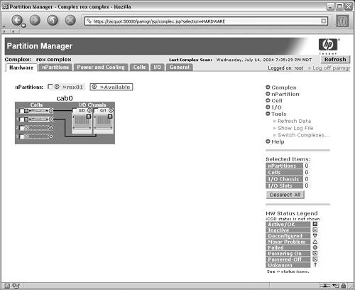 Partition Manager color-codes the nPartitions and assigned hardware resources to assist in distinguishing resource assignment. In addition to color-coding, each hardware resource has a small icon with a number indicating nPartition assignment. In this example, rex01 is assigned nPartition id 0 (zero); therefore, the circle next to the resources assigned to the nPartition contains a zero. Available or empty cell and I/O chassis slots contain an "A" in the circle to indicate the resource is not assigned to any nPartition and is therefore available. Figure 4-7 shows another view of the rex complex, this time focusing on a detailed view of the cells. This view is available by selecting the "cells" tab at the top of the screen. The upper portion of the page provides several tables with summary information for the cells, CPUs, and memory in the complex. From the cells table it is clear there are two active cells and two absent cells. The two absent cell slots will be populated with new hardware in this scenario. Figure 4-7. Partition Manager Cell View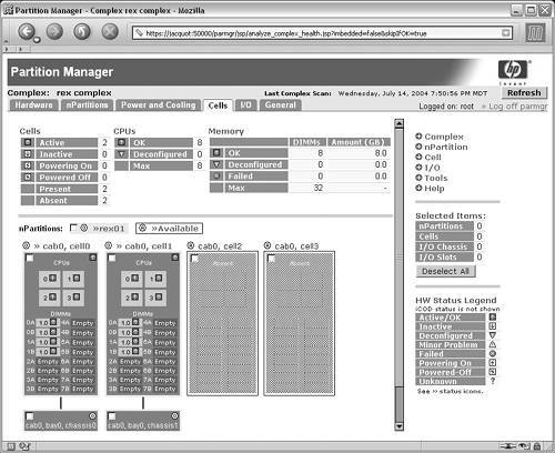 In addition to the summary tables, each CPU, including multi-core CPUs, is shown, as is the status of each CPU. Every DIMM is shown with its size and status. The label alongside the DIMM slot is the actual silk-screen label found on the physical cell board. Should any CPU or DIMM be deconfigured or failed, this screen provides vital information in the process of troubleshooting and physical repair because an administrator can quickly determine the problem area. Viewing the Complex after Installing HardwareFrom the analysis performed, it's clear the new cells should be added into cell slots 2 and 3. Additionally, there are no empty I/O chassis slots, so an I/O expansion cabinet must be installed in order to configure additional nPartitions. The I/O expansion cabinet is required because every nPartition requires at least one cell that is connected to an I/O chassis and that chassis must contain a core I/O card. For the purposes of this example, assume the new hardware has now been installed and power has been enabled. Figure 4-8 shows the state of the complex with the new hardware installed. Cell slots 2 and 3 now contain cells that are inactive. They are each physically connected to an I/O chassis in the I/O expansion cabinet with an ID of eight. Figure 4-8. Partition Manager View after Hardware Upgrade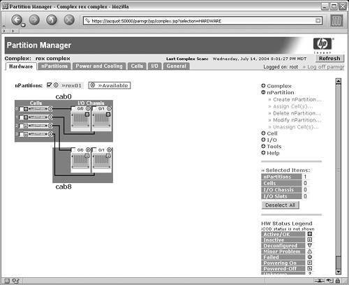
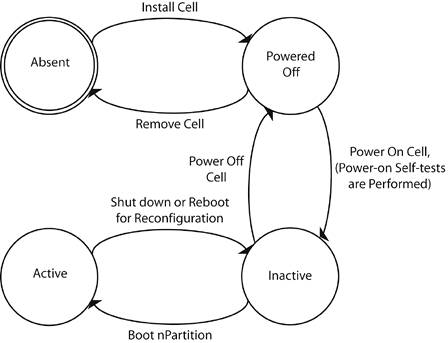
Extending the Existing nPartitionThe first step in the process of putting the new hardware resources to use is to extend the rex01 partition. Notice in Figure 4-8 that the checkbox next to the rex01 partition is selected. From the actions menu on the left-hand side, the Modify nPartition task under the nPartition portion of the menu is selected. This task provides an interface to modify attributes for the nPartition such as the cells assigned to the nPartition and the nPartition name. The Modify nPartition screen is shown in Figure 4-9. Notice the checkbox next to cell 2 has been selected indicating it should be added to the rex01 nPartition. Other settings for the nPartition, such as cell local memory, core cell choices, and the name of the nPartition could also be changed from this dialog by selecting the other tabs. For the purposes of this example, only the new cell will be added. Figure 4-9. Partition Manager Modify nPartition Screen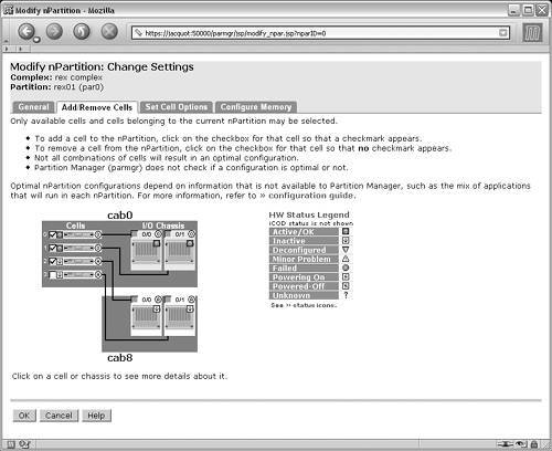 When the OK button is pressed in the Modify nPartition dialog, the Modify nPartition Finish dialog, Figure 4-10, is displayed. This dialog provides a list of notes and warnings, a summary of the changes which will be performed to the complex, and a list of advisory high availability (HA) checks. Figure 4-10. Partition Manager Modify nPartition Finish Dialog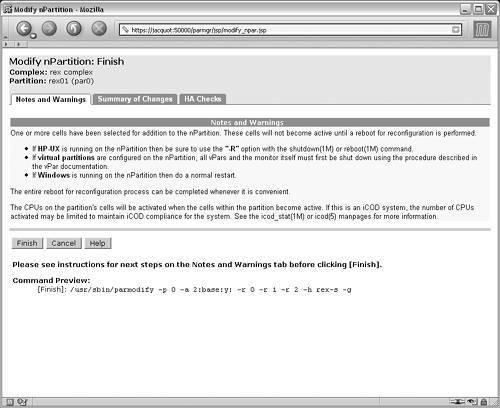 The Command Preview immediately below the buttons provides the exact command that could be executed to perform the requested changes. This is especially useful for administrators who prefer using the command-line interface but have yet to master the various command-line arguments and options. The command parmodify is used to modify nPartitions. Of particular interest in the command are the h and g command-line arguments. These options are required when using the nPartition management paradigm presented in Figure 4-5 for using remote management via the MP. This is required because the nPartition configuration privilege was set to "restricted" in Listing 4-1. As described earlier, this setting prevents changes to the SCCD data structure such as assigning cells to an nPartition. Pressing the OK button will result in Partition Manager executing the command shown in the Command Preview, which will assign cell 2 to the rex01 nPartition, which has the nPartition ID of 0 (zero). Creating a new nPartitionThe rex01 partition is now extended to the desired size, as shown in Table 4-5. The final configuration task associated with the hardware upgrade is to create the new nPartition, rex02. Figure 4-11 shows the rex complex with the changes made thus far. Notice that cell 2 and the attached I/O chassis 0/0 are assigned to rex01, but they are not active (as indicated by the icon next to the cell). Cell 3 and I/O chassis 8/0/1 are both available and will be used to create the new nPartition rex02. Figure 4-11. Partition Manager Hardware View before Creating Second nPartition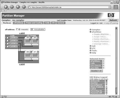 The Create nPartition link is selected from the nPartition portion of the actions menu, which opens the Create nPartition wizard. The first step in creating an nPartition is to set the name. In this example, the name of the nPartition is rex02. The second step is to select the cells that will be assigned to the nPartition shown in the Create nPartition Select Cells screen in Figure 4-12. This screen allows simple point-and-click selection of the cells to be assigned to the nPartition. In this example, the only cell available is cell 3, so it is selected with a checkbox next to the cell. Figure 4-12. Partition Manager Create nPartition Dialog: Select Cells Page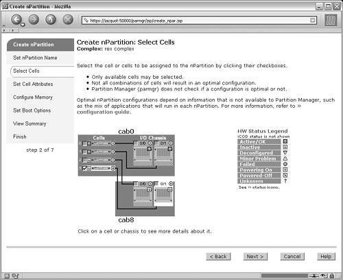 Subsequent steps in the Create nPartition wizard are similar to the options available in the Modify nPartition dialog. Setting the core cell choice, configuring cell local memory, and other options are all available in the wizard. Before performing the requested changes to the complex, consult the summary pages Partition Manager provides, which give detailed information regarding the nPartition that will be created. The final step in the process of creating an nPartition is the Finish page, show in Figure 4-13. As with the Modify nPartition task, the Command Preview is presented. Once again, remote management via IPMI over LAN is being utilized, as is evident by the h and g command-line options. Figure 4-13. Partition Manager Create nPartition Dialog: Finish Page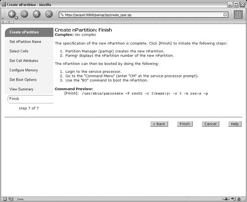 The changes to the rex complex are now complete. The rex01 nPartition has been extended to include the newly added cell 2 and I/O chassis 8/0/0. The rex02 nPartition has been created using the remaining new hardware resources, cell 3 and I/O chassis 8/0/1. Figure 4-14 shows the final configuration of the complex. Notice, however, that the newly added resources are inactive, as shown by the icon next to each hardware component. Rebooting the rex01 nPartition and booting the rex02 nPartition are the final steps in this example scenario. Figure 4-14. Partition Manager Hardware View after Complex Reconfiguration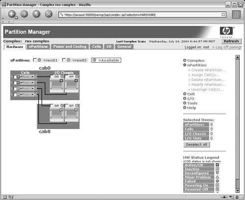 Rebooting and Booting nPartitionsThe complex configuration tasks related to the hardware upgrade are complete. However, the new resources are not usable for workloads. The rex01 nPartition must be rebooted and the rex02 nPartition must be booted in order for the new hardware to be usable. Before jumping into the process of rebooting and booting nPartitions, a discussion of the states of cells is warranted to clarify the process of configuration an HP nPartition server. As shown in Figure 4-15, there are four cell states. When cells are not physically installed, the nPartition management tools refer to the cells as absent. After initially installing a cell, it will be in the Powered-Off state. Enabling power to the cell causes the cell to go through a series of power-on self-tests. These tests ensure that the CPUs, memory, I/O, and other hardware entities are functioning appropriately. After the power-on self-test sequence, a cell stops at the "Inactive" state; this is also known as the Boot Is Blocked (BIB) or Boot Inhibit Bit (BIB) state. Cells 2 and 3 are Inactive, or at BIB, in Figure 4-14. The final cell state is the "Active" state. This is the state that will most commonly be observed on production systems, as only active cells are able to run operating systems and workloads. Cells 0 and 1 are Active in Figure 4-14. Figure 4-15. HP nPartition Server Cell State Diagram
While it is possible to make changes to a complex when cells are in the Active state, it is generally not the recommended approach. Every cell contains a copy of the SCCD data structure that mirrors the copy contained in the MP. When changes are made to the SCCD affecting an active cell, the change cannot be pushed out to any cells until the affected cell becomes inactive. Therefore, a Pending SCCD data structure results. This Pending SCCD will persist until the affected cell becomes inactive, which could be an indefinite amount of time. In addition, no other changes can be made to the SCCD data structure until the change is pushed out. In some cases it is necessary to make changes to the SCCD that affect an active cell, and in those cases, it is recommended that the nPartition be rebooted as soon as possible to minimize the amount of time the Pending SCCD data structure persists. The addition of cell 2 to the rex01 nPartition did not create a Pending SCCD because the only affected cell, cell 2, was inactive when the change was made. Therefore, the copy of the SCCD for cell 2 was pushed out immediately. Similarly, when the rex02 nPartition was created, only cell 3 was affected, and it was inactive when the nPartition was created. The state of an nPartition is related to the cell states shown in Figure 4-15; when one or more assigned cells are in the active state, then the nPartition is said to be active. Otherwise, the nPartition is inactive. The rex01 nPartition must be rebooted for reconfiguration in order for cell 2 to communicate with the other cells in the nPartition and become active. The HP-UX operating system requires special command-line options when rebooting the operating system in order for complex configuration changes to take effect. The R option is required for both the shutdown and reboot commands on HP-UX. This requirement is shown in the Notes and Warnings section of Figure 4-10. If rex01 were running Microsoft Windows or Linux, a normal reboot would result in activation of cell 2 and the original two cells. The difference in behavior on HP-UX allows an administrator to alter the SCCD but have finer control over exactly when the changes to the SCCD take effect. A normal HP-UX shutdown or reboot command with the R option omitted reboots the operating system without activating the newly added hardware in the nPartition. Finally, rex02 must be booted by using the MP's command menu. The boot, bo, command boots the nPartition, releasing the cell from BIB and allowing it to become active. The cell proceeds to either the BCH firmware interface on a cell that contains PA-RISC processors or to the Extensible Firmware Interface (EFI) on a cell that contains Intel Itanium Processor Family (IPF) processors. From the firmware interface, an operating system can be installed and then workloads can be started. Figure 4-16 shows the final hardware view of the complex after the upgrading the hardware, reconfiguring the complex, rebooting rex01, and booting rex02. Figure 4-16. Partition Manager Hardware View after Hardware Upgrade Complete |
EAN: 2147483647
Pages: 197