Entity-Relationship Modeling
| for RuBoard |
In 1976, Peter Chen published the first specification for viewing relational data as a collection of relationships between entities in "The Entity Relationship ModelToward a Unified View of Data." Chen's work (along with that of other theorists such as Hammer and McLeod, proponents of the Semantic Data Model) gave rise to E-R diagramspictorial depictions of entity relationshipsnow a mainstay of logical data modeling.
One of the first things you'll discover about E-R modeling is that there's no sequential path from business processes to fully defined logical data models. Constructing entity relationships requires a lot of thought. It's a process you'll probably go through repeatedly before you feel comfortable with a given model.
Types of E-R Diagrams
E-R diagrams usually come in one of two flavors. First, there's the standard Chen notation. Chen-style E-R diagrams approach modeling very granularly: Each diagram typically represents just one relationship between two entities. Figure 5-11 illustrates a simple Chen-style E-R model:
Figure 5-11. An E-R diagram that follows the original Chen methodology.

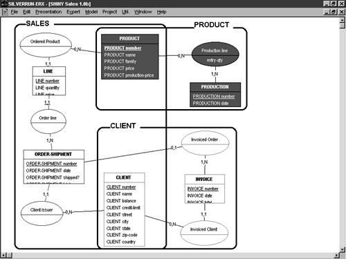
The second type of E-R model is the detailed E-R diagram. Detailed E-R models have come about because the piecemeal approach taken by Chen-style notation results in hundreds (or even thousands) of individual diagrams for complex database designs. This isn't usually the case with detailed E-R models because all the relationships for a given entity are depicted in a single diagram. The diagram is entity-centric rather than relationship-centric. Detailed E-R diagrams usually contain attribute-level information and deviate from simple Chen-style notation in significant ways. Figure 5-12 shows what a detailed E-R diagram might look like.
Figure 5-12. A more detailed E-R diagram that deviates from the classic Chen style.
Generally speaking, entities you define in E-R diagrams will correspond to tables in your relational model and later in your physical database implementation. This is why many popular E-R tools blend in elements of the relational model and physical design with E-R modeling. It's more economical to show the correlation between entities and tables than to force users to keep them separate.
E-R Modeling Terms
Before we get very far into E-R modeling, we need to cover some basic modeling terms. Knowing these is essential to understanding the discussions that follow. The list in Table 5-2 isn't meant to be exhaustive, but it should give you a good sampling of the terms you'll encounter in this and other technical literature that broaches the subject of E-R and logical data modeling. Some of these terms apply only to E-R modeling; some relate to logical data modeling in general.
Table 5-2. Glossary of Essential E-R Data Modeling Terms
| Term | Definition |
|---|---|
| Entity | A real objecta person, place, event, or thingabout which you want to store data. Entities are also known as entity classes. |
| Entity instance | A specific item represented by an entity class. For example, customer John Doe would be an entity instance of the CUSTOMER entity class. Entity instances are sometimes referred to as entity occurrences. |
| E-R modeling | A type of logical data modeling that assumes all business elements can be generalized into archetypal idealsabstract concepts. These conceptual entities are described in terms of their characteristics or attributes. They are related to one another through the actions they perform on each other. These actions establish relationships between the entities. E-R modeling visually depicts these relationships. |
| Subtype | An entity class that is a subset of a larger, more inclusive type of entity is known as a supertype . For example, the entity class FIREMAN may be a subtype of the supertype CITYWORKER. Subtypes typically inherit the supertype's attributes and relationships, and reserve the right to define their own. Groups of subtypes (e.g., FIREMAN, POLICEMAN, GARBAGEMAN) are known as subtype clusters. |
| Supertype | An entity class that is a superset of smaller, less inclusive entity classes, known as subtypes. For example, entity class AUTOMOBILE may be an entity supertype of the FORDAUTO, GMAUTO, and CHRYSLERAUTO entity subtypes. You'll often hear subtypes and supertypes referred to collectively as s-types. |
| Attribute | A characteristic of an entity or entity relationship. Attributes describe entities in detail. For example, SocialSecurityNo would likely be an attribute of the EMPLOYEE entity class. |
| Domain | A particular type of data or range of values that an attribute allows. For example, applying the TDate domain to the HireDate attribute might require that all HireDate entries be valid dates. Likewise, applying the TNonZeroCost domain to the Price attribute might require that all Price values be nonzero. |
| Domain integrity | The rules that control the types of data a domain allows. Ensuring domain integrity, for example, makes certain that values contained in the Date domain are indeed valid dates and that values stored in Numeric attributes are indeed numbers . |
| Relationship | A link between two entities that establishes the behavior of one entity when something happens to the other. There are five basic types of entity relationships: one-to-many, many-to-many, one-to-one, mutually exclusive, and recursive. |
| Relational integrity | The rules that ensure relationships between entities are respected. For example, relational integrity would prevent the deletion of CUSTOMER entity instances that still have associated INVOICE entity instances. |
| Connectivity | Defines the mapping of associated entity instances in a relationship. For example, defining the connectivity between the INVOICE and CUSTOMER entities might specify that for every instance of the CUSTOMER entity, there can be many corresponding instances of the INVOICE class, because each customer can place multiple orders. |
| Cardinality | The actual number of related instances between the entities in entity relationships. It quantifies abstract relationships by elaborating on connectivity. For example, the cardinality between the INVOICE and CUSTOMER entities might ensure that for every INVOICE instance, there is at least one corresponding CUSTOMER instance. |
| Modality | Specifies whether the existence of an entity instance is optional or required in a relationship. Modality (also referred to as optionality or existence ) refers to the minimum cardinality of relationships between entities. |
| Normalization | The removal of a data model's redundant, inconsistent, and convoluted elements. The idea behind normalization is to ensure that each entity instance represents no more than one real-world object. |
| Entity Identifier | The combination of attributes necessary to distinguish one entity instance from another |
There is a direct correlation between E-R modeling terms and relational modeling terms. Table 5-3 cross-references some of the E-R terms you just learned with their relational counterparts.
The best modeling tools treat E-R modeling as a subset of relational data modeling. Not only does E-R modeling not constitute the entirety of logical data modeling, it's also independent of physical design.
Now that you have an understanding of some basic modeling concepts, let's proceed with modeling the entity relationships necessary to support the processes you defined earlier.
Building Your E-R Model
Thanks to having defined a complete business process model before beginning the E-R modeling process, you'll spend a lot less time developing a working E-R model than you otherwise would have. In this chapter, the main thing you'll accomplish by constructing an E-R model is normalizing your data.
Table 5-3. Cross-reference of E-R Terms with Relational Modeling Terms
| E-R term | Relational or logical design term |
|---|---|
| Entity | Table |
| Entity occurrence/instance | Row |
| Entity identifier | Primary key |
| Unique identifier | Candidate key |
| Relationship | Foreign key |
| Attribute | Column |
| Domain | Data type |
NOTE
As a rule, normalization is a function of the relational data modeling or database design process. In this book, we're treating E-R modeling as the first step of this process. Some people completely separate the two types of modeling. Some go straight from E-R modeling to constructing database objects; others build relational models without bothering with E-R diagrams. In this book you'll learn to do both types of modeling. Once you finish modeling your entity relationships, you'll complete your logical database design. Although it may seem intuitive to hold off normalizing your data until the logical data modeling stage, most E-R tools provide normalization facilities of some sort , so we'll cover it here.
Let's get started building an E-R model for the lease business process model we designed earlier. Create a new E-R model, and, if your tool supports it, import your business process model from earlier (reference it in your tool's repository if necessary).
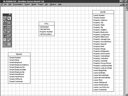
Insert each store from the business process model into your new E-R diagram. Depending on your tool, this should create entity objects that correspond to the store objects you defined in your process model. Your tool may prevent you from inserting the PROPERTY store because it does not have an associated data structure. Figure 5-13 shows what your model might look like so far.
Figure 5-13. Your model with the entity objects derived from your repository in place.
If your E-R tool has a normalization expert, you can avoid the tedium of having to normalize the model yourself. Without a normalization wizard or facility, the next step may be to decompose your entities into normalized entity classes, then link them to one another via entity relationships. This is generally the way things are done with E-R modeling.
If your tool sports a normalization wizard, you'll get to skip some of the real work of data modeling. In many cases, these types of facilities can completely normalize a model just by asking a few simple questions.
NOTE
I should point out here that some normalization wizards do an incomplete job of normalizing a database. You should always check the work of a normalization program before assuming it's right (which is another good reason to have an in-depth understanding of normalization yourself).
Assuming your E-R diagramming tool supports a normalization wizard or facility, invoke it now to normalize the model. Figure 5-14 illustrates what the model should look like once normalized. Arrange your entities and their associated relationships so that they do not overlap one another in the diagram.
Figure 5-14. Your model as it should appear after normalization.
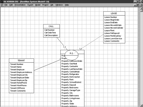
After you've normalized your model, you should see a new entity, the PROPERTY entity. This entity should have been added by the normalization expert due to redundancy in the LEASE entity. Set its name to PROPERTY. Figure 5-15 shows what the model should look like this far.
Figure 5-15. Normalization results in a new entity being added to your design.
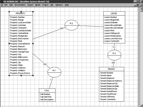
When you designed the data structure objects for the process model you defined earlier, you may have wondered why I didn't ask you to create a data structure for the PROPERTY store. Now you know the reason. The attributes needed by the PROPERTY store were already embedded in the LEASE data structure. I left them there to illustrate the power of using a CASE tool to assist in modeling data. Your E-R tool should have pulled those attributes relating to property from the LEASE entity and placed them in the new PROPERTY entity. The Property Number attribute should also have been copied from the CALL entity.
Normalization
Because you likely just watched it happen before your very eyes, I suppose I should outline exactly what normalization is. Beyond the earlier glossary definition, normalization seeks to save work and reduce the potential for errors when updating database table rows. For example, if you store a customer's address in every Invoice record, changing the customer's address means changing every occurrence of it in the Invoice table. If, on the other hand, that address information is stored separately in a Customer table, it only has to be changed in one place, greatly reducing the time it takes to change a customer's address as well as eliminating the possibility of a row in the Invoice table being missed.
Normalization is formally divided into five forms or stages, first normal form through fifth normal form. These obscure terms really just refer to the five sets of relational criteria that an entity either does or does not meet. Each successive stage builds on the previous one. Although there are technically five basic forms, in practice you'll probably use just the first three. The last two are generally regarded as too specialized for commonplace database design.
NOTE
Alhough we haven't yet discussed relational design in depth, I'm going to use relational terms like table , row , and column interchangeably with E-R terms like entity , entity occurrence , and attribute in the normalization discussion that follows. This is because I think the examples I give for each normal form will be easier to follow if expressed in terms of relational and physical database objects rather than abstract concepts.
First Normal Form
In order for a table to be considered normalized to first normal form (1NF), each of its columns must be completely atomic and it must contain no repeating groups. A column is atomic when it contains only one element of data. For example, an Address column that contains not only a street address but also a city, state, and zip code is not completely atomic. Columns designed this way should be split into multiple columns to be fully compliant with first normal form. Keep in mind that the degree to which you should break down a column depends on its intended useas with all things: be sensible .
A repeating group is a column that is repeated within a row definition for the sole purpose of storing multiple values for that attribute. For example, we could have taken the approach in designing our Tenant table of storing the property the tenant was renting within the Tenant table rather than separately in the Property table. This fails to allow for the possibility that a single tenant (for example, a corporation leasing a number of corporate apartments) may rent more than one property. To address this exclusively within the Tenant table, we would have to decide on the maximum number of properties a tenant may rent, then add the requisite supporting columns to the table. These repetitive columns would constitute a repeating group.
Some database tools and languages provide direct support for repeating groups, and, thereby encourage nonrelational design. Obviously, a design cannot be relational if it violates first normal form. An example of such a tool is Advanced Revelation. Its multivalue columns are actually repeating groups. Using them, which is a popular practice in AREV applications, violates first normal form. A similar nonrelational construct is Perl's associative array. Associative arrays are collections of name/value pairs that are stored as single variables . Although powerful in practice and certainly handy, they encourage coding and, thereby, database design, which violates first normal form. Another fine example of nonrelational language support is COBOL's groupname occurs several times syntax. COBOL's support for nonrelational elements isn't as surprising as it may seem because it predates relational databases. These types of constructs are to be avoided if you want to build well-designed relational database applications.
Whether you're building a database or a database application, repeating groups are a very poor design practice. I mention applications here because application design inevitably affects database design. After all, the information that's being shuffled around inside an app will most likely need to be stored at some point. As a practical matter, repeating groups present a number of design difficulties. First, returning to the Tenant table example, if we were to store all the properties rented by a tenant within the Tenant table, every tenant row would include the repeating property columns regardless of whether they were used. This would no doubt waste space in the database. Second, repeating groups present a challenge when it comes to processing the data they represent. In particular, properly formatting them on printed reports can be difficult. Not only do you have to deal with sets of rows, but you also have to deal with sets of columns, turning a one-dimensional task into a two-dimensional one. Third, if the maximum number of properties that a tenant may rent needs to be increased, the structure of the Tenant table must be changed, along with any applications that access it.
Second Normal Form
In order for a table to be normalized in second normal form (2NF), each of its columns must be fully dependent on its primary key and on each attribute in the primary key when the key consists of multiple columns. This means that each nonkey column in a table must be uniquely identified by the table's primary key. Tables with a single-column primary key that are 1NF compliant are already 2NF compliant.
Let's take the example of the Invoice table again. If the table's primary key consists of the LocationNo and InvoiceNo columns, storing the name of the location in each row would violate second normal form. This is because the LocationName column wouldn't be uniquely identified by the entirety of the primary key. It would depend only on the LocationNo column; the InvoiceNo column would have no effect on it. Instead, the LocationName column should be retrieved from the Location table through a join whenever it's needed, not permanently stored in the Invoice table. For a table to be 2NF compliant, all nonkey columns must be fully functionally dependent on the primary key. Transitive dependencies, however, are still allowed.
Third Normal Form
In order for a table to be normalized in third normal form (3NF), each of its columns must be fully dependent on its primary key and independent of each other. So, along with meeting the qualifications of second normal form, each nonkey column in a table must be independent of the other nonkey columns. This means that, unlike 2NF, 3NF does not allow transitive dependencies.
Let's return to our Invoice table example. Let's say that the primary key of the table is again both LocationNo and InvoiceNo. One of the nonkey columns in the table would probably be the CustomerNo column. If, along with the CustomerNo column, the CustomerName column was also stored in the Invoice table, the table would fail the criteria for third normal form because the CustomerNo and CustomerName columns would be dependent on one another. If the CustomerNo column was changed, the CustomerName column would likely need to change with it, and vice versa. Instead, the CustomerName column should be located in a separate table (e.g., the Customer table) and accessed through a join when needed.
NOTE
An elaboration of third normal form, called Boyce-Codd Normal Form (BCNF), requires that each column on which another column depends must itself be a unique key. The column sets that can uniquely identify rows are known as candidate keys. A table's primary key is selected from these candidates. BCNF requires that any columns that depend on other columns must only depend on one of these candidates. This means that all determinates must be candidate keys. So, BCNF refines third normal form by allowing for intercolumn dependencies between candidate keys and nonkey columns. However, this doesn't violate third normal form, as it may appear, because the key on which the dependent columns rely is also a candidate key. It uniquely identifies the row, just as the table's primary key does. So, the dependency of a column on a candidate key other than the table's primary key is a purely academic distinction, because both the primary key and the nonprimary candidate key uniquely identify each row.
If this seems confusing, don't worry about it. Compliance through third normal form is the generally accepted criterion by which a table or entity is said to be normalized. A difference that makes no difference is no difference.
Fourth Normal Form
Fourth normal form prohibits multivalue dependencies from existing between columns. If a column, rather than uniquely identifying another column, limits it to a set of predefined values, a multivalue dependency exists between them. Let's look at the Tenant table that we've been discussing. Let's assume for the moment that the only employer-related information you want to store for a Tenant is his employer's name, so you include the Employer attribute in the TENANT entity. In order for a tenant to have more than one employer (let's say he's a workaholic and writes books at night), you'd have to have a separate row in the Tenant table for each of his employers . All the attributes in each row would be identical, with the exception of the Employer attribute. It would differ between rows for a given tenant.
The relationship between the other columns in Tenant and the Employer column would amount to a multivalued dependency. For each TenantNo column, you might have multiple Employer values. As a matter of practice, you may want to allow for the possibility that a tenant could have more than one employer. Also, although unlikely , knowing which tenants work for a given employer may be of interest to you as well. In order to be fourth normal form compliant, then, you would have to create a separate table whose whole purpose is to cross-reference tenants with employers. Ideally, this new table would have just two columns TenantNo and Employer with both of them serving as parts of a compound primary key. Then, when you needed to list all the information for a given tenant, you would join the Tenant table with the new cross-reference table using their common TenantNo column.
In the real world, finding tables that are not fourth normal form compliant is not uncommon. Decomposing entities beyond third normal form sometimes results in more entities than people care to deal with. What is theoretically sound is not always practically sensible.
Fifth Normal Form
Fifth normal form stipulates that if a table has three or more candidate keys and can be decomposed without losing data, it should be broken into separate tables for each candidate key. Fifth normal form comes into play very rarely for a couple of reasons. First, it's unusual to find a table with three or more separate column sets that uniquely identify rows. Second, excessive decomposition can result in inaccurate joins, such as those that produce new rows. For the most part, you don't see fifth normal form applied (or even discussed) in the real world. I include it here only for reference.
Normalize, But Don't Overdo It
When you begin normalizing your data, it's important not to get too carried away. Overnormalization can have a devastating effect on performance. It can also needlessly complicate your database design. For instance, consider the example I mention in the discussion on fourth normal form. You may be tempted to set up a separate table for the employer information currently stored in the Tenant table. After all, Employer and EmpAddress are clearly dependent on one another, in violation of third normal form. But what real benefit would you realize from doing this? Probably very little. Employer information is probably only of interest to you as it relates to a given tenant. For example, you probably wouldn't care to list all tenants working for a given employer. And let's assume that you don't care to store more than one employer per tenant and that you'd never want to change all employer-related information en masse. If this is the case, setting up a separate table for tenant employers would likely add needless complexity to your model and generally be a waste of time.
There are also times when limited denormalization is the only way to get the performance you need. This is especially possible when working with large amounts of data. For example, suppose that you've built an application that processes millions of credit card receipts each day. Among other things, each receipt lists the card number, the amount of the transaction, and the card's expiration date. At the end of each day's work, your system needs to be able to print a report of all the credit cards used, the net amount of the day's transactions for each card, and each card's expiration date. Because you can easily join to the base credit card table to retrieve the expiration date of each card, you wisely normalize the credit card transaction table by not storing the expiration date from the receipts in it. This saves space in the database and avoids redundancy in the design. This is a better relational design, but has the unfortunate side effect of making your report run twice as long. It runs so long, in fact, that your client finds the application's performance unacceptable.
Speaking only in terms of database design, the resolution to this may be to store and use the expiration date as it is received in each transaction. Although this introduces redundancy into the database, it is controlled redundancy, and it is done by design for a specific purpose. Often, this is an acceptable deviation from strict relational policy.
The rule to follow when introducing controlled redundancy into a database design is this: First fully normalize the database, then introduce redundancy only when absolutely necessary. Resist the temptation to denormalize on a whim or to pass off poor relational design as performance tuning. Unless you work with very large sets of data, denormalizing is rarely necessary.
Completing Your Model
Technically speaking, your model is now normalized, but there still remains work to be done. For one thing, no entity identifiers (primary keys) have been defined yet for the model. For another, we haven't checked the connections between the entities for correctness.
Verifying Connectivity
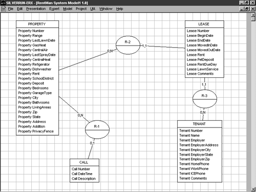
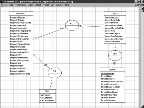
Let's begin by verifying that the decisions made by the tool regarding entity connectivity are correct. There's a minor problem with your E-R diagram as it's currently defined. Look over Figure 5-15 and see if you can spot it. If you discover it, go ahead and correct it in the model. Figure 5-16 shows the model as it should appear. Compare it with Figure 5-15 and notice the change that occurred in the relationship between the CALL entity and the PROPERTY entity.
Figure 5-16. Your model after its connections have been verified .
Specifying Cardinality
Notice that the connectivity between the CALL and PROPERTY entity was changed from 1,1 to 0,1. What does this mean? The numbers you see on the diagram in Figure 5-16 represent the minimum and maximum cardinality, respectively, for the entities in the relationship. That is, a cardinality of 1,1 between the CALL and PROPERTY entities indicates that, at a minimum, at least one corresponding instance must exist in the PROPERTY entity for each instance in the CALL entity. In terms of the database itself, this means that each row stored in the Call table will require a valid PropertyNo from the Property table. PropertyNo cannot be left blank. As a manner of normal course, though, a PROPERTY instance need not exist in order for a CALL to exist (a person might call who doesn't yet lease a property), so Figure 5-16 reduced the minimum cardinality to 0. A zero cardinality is necessary if the leasing company wants to be able to record calls that don't reference a particular property, such as prospective tenant inquiries. This will allow the Call table's PropertyNo column to be left blank. You can't require the existence of a property reference in every call if you intend to record calls that don't reference properties.
Similarly, the maximum cardinality of 1 stipulates that, at a maximum, there can be just one corresponding PROPERTY instance for each CALL instance. This means that a given row in the Call table will be able to reference just one property. It may not reference multiple properties. Again, this is a good decision given that calls would normally either reference no specific property (such as during an inquiry by a prospective tenant) or a particular one (such as a repair request by a tenant).
Cardinality relationships are depicted from the perspective of the nearest entity. That is, you can construct a sentence like the following to make entity cardinality easier to comprehend:
For each NEAR ENTITY row, I need a minimum of MINIMUM CARDINALITY corresponding rows and a maximum of MAXIMUM CARDINALTY corresponding rows in the Far Entity table.
So, in this case, you'd construct the following sentence to express the cardinality of the CALL-PROPERTY relationship:
For each CALL row, I need a minimum of 0 corresponding rows and a maximum of 1 corresponding row in the Property table.
Note that a separate sentence is needed to express the relationship from the perspective of the PROPERTY entity. One sentence is usually not enough. For example, although a PROPERTY instance may not require the existence of a LEASE instance, a LEASE instance certainly requires a corresponding PROPERTY instance.
Entity relationships are frequently expressed in terms like these, and many CASE tools support annotating E-R diagrams with these types of sentences. Another way of expressing entity relationships as sentences follows this format:
PARENT ENTITY has at least number CHILD ENTITY.
So, returning to the CALL-PROPERTY example, you'd write
CALL has at least zero PROPERTY
to express minimum cardinality.
Likewise, the form
PARENT ENTITY has at most number CHILD ENTITY
can be used to express maximum cardinality. You'd write
CALL has at most one PROPERTY
to express the maximum cardinality between the Call and Property entities. There are a number of variations on this theme, but the idea is basically the same. You should use whatever works best for you.
Choosing Entity Identifiers
The next step in completing your E-R model is to select an identifier for each entity. An entity identifier will translate into a primary key definition in your relational model.
Entity identifiers come in two flavors: natural identifiers and artificial or surrogate identifiers. A natural entity identifier is an entity attribute (or set of attributes) already present in the entity that uniquely identifies each entity instance. For example, the SocialSecurityNo attribute would be a natural identifier of the EMPLOYEE entity. An artificial identifier is an attribute that's added to an entity for the express purpose of giving the entity a unique identifier.
Adding an artificial identifier may be necessary for a couple of reasons. One, although another unique identifier exists, it may be too large or too unwieldy to work with practically. For example, a user may feel that typing an employee's social security number regularly is too much work and may request a shorter, less cumbersome employee number attribute. A second reason that you may have to add an artificial identifier is that an entity may not initially have a natural identifier. For example, without a CustomerNo attribute, a CUSTOMER entity may not possess an attribute or group of attributes that can uniquely identify each entity instance.
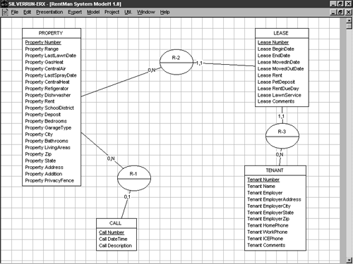
In the case of the entities covered here, each entity has an artificial identifier. Despite the fact that you may be able to combine attributes in some of the entities to produce unique identifiers, for simplicity's sake I had you include surrogate identifiers to begin with. This saves time and helps ensure that you won't have problems later. Using your tool's method for doing so, identify the surrogate key in each of your entities. Table 5-4 lists the entities and their keys:
Table 5-4. The Surrogate Keys for Your Entities
| Entity | Key |
|---|---|
| CALL | Call Number |
| LEASE | Lease Number |
| PROPERTY | Property Number |
| TENANT | Tenant Number |
Figure 5-17 illustrates what your model might now look like.
Figure 5-17. Your model as it might appear once entity identifiers have been defined (keys are underlined ).
Finishing Touches
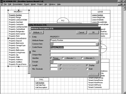
There are a number of additional things we could do to polish the model a bit more, but only a couple of them are really worthwhile. Before we move on to logical data modeling, let's set up cleaner names for the items in your model. By cleaner, I mean abbreviating or condensing your entity, attribute, or other object names to make them more implementation safe. Names that work fine in a diagram may be difficult or impossible to implement as database objects because they contain spaces or other illegal characters. Because the entities you've defined in your model will eventually become tables in your new database, it's important to use names that the target DBMS will accept. Although SQL Server's square brackets allow us to work with names containing otherwise illegal characters , it's smarter and easier just to use good names in the first place. Many E-R tools can clean up the names you've used in a diagram by converting them from human-readable monikers to DBMS-friendly ones. Sometimes no changes are needed; sometimes radical changes are necessary.
If your E-R tool includes a name correction feature, invoke it now to condense the names in your model. Most tools will replace the names displayed in the diagram itself with these abbreviated names; some won't. Some tools store the new names internally; some allow you to choose which names to display on the diagram (the more human-readable versions or their abbreviated counterparts).
Figures 5-18 and 5-19 illustrate the name refinement process.
Figure 5-18. A common technique for handling names with spaces is to use underbars.
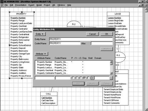
Figure 5-19. It's better to use simpler names than to have to resort to SQL Server's square brackets.
The last thing we'll do before moving on to relational modeling is name and save your model. Most modeling tools allow you to assign a textual name for the models you create that's independent of the filename. A good one for this model is E-R Diagram for Lease Process. Once you've named your model, save it to disk. You're now ready to move on to relational data modeling. Figure 5-20 illustrates what your completed E-R model might look like.
Figure 5-20. Your completed E-R model.
| for RuBoard |
EAN: N/A
Pages: 223