Section 2.2. Components of the Design
2.2. Components of the DesignHaving glimpsed the BPM architecture "from 30,000 feet," we now descend to a lower altitude to get a closer look at each of its major components. This section examines the requirements and proposes designs for the notations and graphical tool, the runtime engine, the human and system interaction interfaces, the administration and monitoring facilities, and the CDL toolkit. 2.2.1. Notation and Graphical ToolThe need for a graphical process modeling language is often overlooked in the BPM standards race. Most BPM languages are XML-based and can be relatively difficult to compose or read. Design is best communicated with diagrams. Scan through a typical object-oriented component design document, for example, and you will discover that a single UML class diagram can convey most of the intended meaning, making many of the surrounding words redundant. If a picture is sufficiently rich, it is worth more than a thousand words! Standardization adds even more value. A diagram that is drawn to a standard specification is familiar to a wide audience, and its semantics are also clearly understood. Readers get the gist of a haphazardly drawn assemblage of boxes and arrows, but the lack of precision in representation makes it less intelligible. BPM has two good graphical modeling notationsBPMN (Chapter 6) and the UML activity diagram (Chapter 3)but BPMN is the preferred choice for our architecture because it is more expressive (it supports most of the "P4" patterns described in Chapter 4) and has a mapping to BPEL. ITpearls' Process Modeler tool, for example, is a BPMN drawing tool with BPEL export capabilities. As Figure 2-4 shows, ITpearls provides a set of stencils that are imported into Microsoft Visio. A BPMN diagram is drawn by dragging shapes from one of the stencils onto a canvas sheet. The ITpearls tool also embeds a Process menu in the Visio menu bar. As shown in the figure, the designer can export the diagram to a file; at the time of writing, this function was planned for BPEL and BPML formats but was not yet available. The ability to manage the technical implementation detail is one of the greatest shortcomings of modeling languages. A BPMN drawing dragged onto a Visio canvas captures perhaps 75% of the required processing, but the remaining 25% requires Figure 2-4. ITpearls' BPMN drawing tool with Microsoft Visio development tool capabilities, such as a source code editor and property sheets. For example, the following are not easily modeled using drag-and-drop tools:
Serving both business and technical users is challenging because business users generally want details hidden, whereas technical users require the power of a scaled-down integrated development environment. A worthwhile process modeling tool resolves these tensions by providing different views of the process: a simpler business view that controls the overall shape of the process and a technical view that has full reign over the behavior of each step. 2.2.2. Runtime EngineA BPM engine, like a computer, loads programs (called process definitions) and runs instances of them (called processes). A BPM program is a series of steps, and the job of the engine is to run through the steps, much like a computer processor runs through lines of code. A BPM program is also highly event-driven, meaning that it spends much of its time waiting for a stimulus to awaken it, at which point it performs a burst of activity before returning to sleep in anticipation of the next event. A BPM program also calls other systems. The BPM engine is responsible for detecting events, injecting them into the process, and managing outbound message calls, as shown in Figure 2-5. Figure 2-5. BPM runtime engine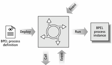 The preferred execution language, BPEL (discussed in Chapter 5), is the most advanced and popular XML process language. Exactly how a BPEL engine works is largely irrelevant because the architecture treats is as a black boxso buy an engine from a reputable vendor, instead of building your own! NOTE For Java programmers keen to see a good implementation of a BPEL engine, the open source ActiveBPEL is a good bet. The web site http://www.activebpel.org provides source code, binaries, and documentation, including a high-level description of the engine's architecture. 2.2.3. Human InteractionThe application's support for human participation in a process requires a worklist interface that allows the process to coordinate that is, initiate, then wait for completion ofmanual work tasks. Users view and execute pending tasks in a user-friendly graphical console designed for usability and productivity. Figure 2-6 illustrates a web-based worklist console, known as the Travel Agent Portal, for a travel agency. The user, named Bill Smith, sees three panels. The banner at the top of the second panel welcomes him to the site and reports that he performs the roles of Agent and Supervisor. The left panel is a command menu that, among other things, presents him with links to view three lists of tasks: Resolve Error, Escalations, and Approvals. (The number in parentheses indicates the size of the list.) When one link is clicked, a summary of the task list is populated into the main panel in the bottom right. Currently, the panel shows the Resolve Error list. When the user clicks on one of its items, a separate window pops up Figure 2-6. Human worklist console for a travel agency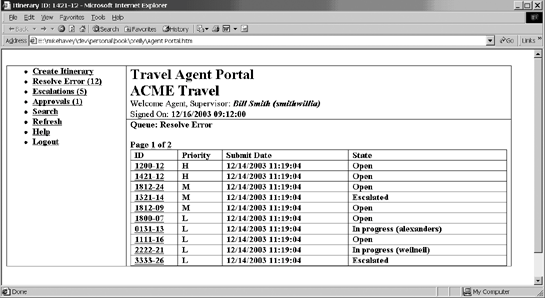 showing information about the task and providing an editable form to complete it and send it back to the waiting process. Behind the scenes, a web service called the Worklist offers two operations:
The state of the task is persisted to a system management database (described in detail in the later section "Administration and Monitoring"). On initiateTask, the Worklist web service writes the details of the task to a table; the worklist console pulls data from that table for display to the user and updates it as the task progresses. The normal sequence of events is shown in Figure 2-7. The figure shows two classes: Worklist, stereotyped as a web service, and AdminDB (typically a set of stored procedures or a Java or C# data access object), representing the typical accesses to the database for task management. In the sequence diagram, when the process invokes the Worklist's initiateTask( ),Worklist persists to the database, via assign(), a record of the initial assignment (e.g., Resolve Error is assigned to role Agent). The worklist console, when the user clicks on a Worklist link, performs the query queryTasks( ) to draw a summary of tasks, and when the user selects one of the tasks, calls getTaskDetail( ) to show the full set of task data. The user then "claims" the task (more on this next) and completes it (claim( ) and complete( ), respectively), at which point the Figure 2-7. Worklist interface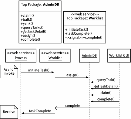 console signals to the Worklist that the job is finished; the Worklist in turn invokes the taskComplete( ) callback, which awakens the BPEL process.[*]
NOTE Several BPM products (e.g., IBM MQ Workflow) have worklist interfaces. Oracle's implementation stands out because it is designed as a web service callable from a BPEL process. In most cases, from the perspective of the process, the identity of the person who actually performs a task is irrelevant. What is important is that person's type or role. Any travel agent, for example, can work a Resolve Error case. But in the end, a particular person does end up doing the work, and a good role-based security model is required to make it happen. Bill Smith is allowed to execute a Resolve Error task, for example, because he has the role of Agent. The security infrastructure leveraged by the BPM architecture should provide two role-based functions:
During its lifetime, a task can change hands several times: from role to user, from user to role, or from user to user within a role. In the simplest case, described in the previous scenario, a task is initially assigned to a role and then claimed by a user having that role. Other possibilities are summarized in Table 2-2.
2.2.4. System InteractionNo process runs in isolation. In addition to its human dependencies, a process invariably calls or is called by various types of software components. There are four possible modes of interaction as shown in Table 2-3.
Components can be divided into those that are external and internal to the company. External interactions are web service-based and follow choreography or collaboration protocols. Internal software interactions can be inline code snippets or client/server interfaces to other systems running on the corporate network. 2.2.4.1 AdaptersThe BPM architecture should aim to support the widest variety of system interfaces. A naïve design would be provide individual hooks for every conceivable technology: the MQ hook, the JDBC hook, the Tuxedo hook, the Java hook, the EJB hook, the COM hook, the web service hook, the JMS hook, and so on. A cleaner, more extensible approach is to provide built-in support for the typical process technologies such as web services and XML, inline code capabilities for Java or C#, and an adapter plug-in model for anything else. The adapter plug-in model requires the following:
In Figure 2-8, adapters for SAP, MQ, mainframe and database are deployed to the engine, sitting alongside natively supported XML, web service, and Java modules. Figure 2-8. System interaction: native and adapter 2.2.4.2 The process is a web serviceIn many contemporary BPM approaches, including BPEL, the process not only interacts with other web services, it is itself a web service. Every receive node, in which the process listens for inbound messages, appears to the outside world as a web service operation. Calling that operation injects an event into the process and causes it to perform a burst of activity before either completing or waiting for the next event. For BPM architects, this feature means that the runtime engine must include a special web services listener that knows how to accept an inbound Simple Object Access Protocol (SOAP) message, inject it into the engine, obtain the response, if any, and send it back out as a SOAP message. On a J2EE platform, because SOAP is typically transported over HTTP, this component can be an HTTP servlet that handles inbound SOAP using HTTP POST and GET methods. The design is depicted in Figure 2-9. Figure 2-9. Servlet as web services listener for engine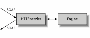 2.2.5. Administration and MonitoringThe mark of a successful production application is a well-conceived and sophisticated set of administration and monitoring tools. The main tool is a graphical console that lets system administrators watch, tune, and perform management actions; in most cases, the console uses (under the covers) a standard management API to converse with the running system. A BPM console should allow operators to monitor running processes, kill hanging processes, install new process definitions, and decommission processes that are no longer required. Internally, the BPM application should support SNMP or JMX management infrastructures to facilitate these operational capabilities. With these interfaces, custom consoles can be developed to meet requirements that are not provided out of the box (e.g., sending an email to a specified group list when an error occurs while deactivating a process definition). The first step in designing a system management interface for a particular system is to identify the managed objects and their services. Table 2-4 summarizes the BPM managed objects and required services.
Figure 2-10 illustrates a typical BPM console that provides these services. The left panel contains a set of links representing the core managed objects. When an administrator clicks on a link, the right panel shows administrative options for the selected object. For example, clicking on Processes brings up the panel ProcessesSearch. The search shown in the diagram will find all processes with definition HandleClaim.bpel that started on or after 2002-01-01 and have a variable called claimID that starts with the text 12. The search is executed by clicking on the Search link. The list of matching processes is shown in Figure 2-11. Figure 2-10. Admin console: process search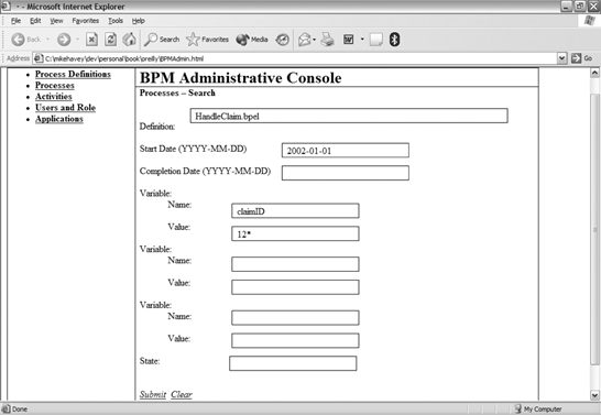 Figure 2-11. Admin console: process search results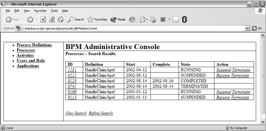 The list provides links (the ID value) to a page that displays the full detail of the process. For convenience, the links under the Action column allow process maintenance without the need to delve into the details. The options listed in this column depend on the state. The first item (ID 1231), whose state is RUNNING, can be suspended or terminated; the second item (ID 4212), which is already SUSPENDED, can be resumed or terminated. 2.2.5.1 PersistenceBecause most processes are stateful and must survive a restart of the runtime engine, the BPM implementation requires a persistent data store in which the process state is kept current in case of engine recovery. The data store is best modeled as a normalized relational database schema. Not only is this approach an accepted practice in contemporary enterprise architecture, it also benefits customers by enabling them to perform ad hoc process queries. Customers might also build reporting databases or data warehouses based on the runtime process persistence model and institute purge and replication jobs that, respectively, cleanup the runtime model and synchronize the reporting model. Figure 2-12 shows a good BPM runtime data model. Figure 2-12. Process data model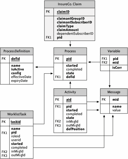 The tables in the model include the following:
Figure 2-12 also demonstrates how the core model can be extended with application-specific data. The shaded table InsureCo.Claim represents an insurance company's representation of a claim. The field pid links the claim to a particular record of the Process table, which represents a specific process instance. The mapping in this case is one-to-one: each claim is handled by one instance of claims business process. Table 2-5 describes some other possible scenarios; significantly, no changes are required to the core tables.
The following examples, based on an Oracle database implementation, illustrate several SQL statements that query the data model. These queries can generate reports or administer the system:
2.2.5.2 Process versioning basicsOver time, the definition of a process needs to change to accommodate bug fixes, enhancements, and new public interfaces. But in a production environment, applying these changes to definitions that have active and possibly long-running instances requires exquisite care. The trick is to make the change without compromising the current base. Depending on the nature of the change, use one of the following strategies:
2.2.5.3 BAM and process miningBusiness activity monitoring (BAM) is an exalted form of process administration and monitoring offered by vendors such as Pegasystems. BAM is targeted at the business manager who requires a sophisticated dashboard with graphical views (often in the form of graphs or charts) of process-related data updated in real time or generated as part of a report. This data can include the state of running processes and their activities, as well as aggregated statistics concerning the business subject matter of processes (e.g., if the process is for loans, view the number of approved loans so far today). Figure 2-13 illustrates a typical dashboard.[*]
BAM can also let the manager make changes in response to emerging conditions. For example, if a given process appears to be stuck waiting for the action of a particular person, the manager can reassign it to someone else. Some BAM implementations can even run on autopilot; rules can be defined to automatically perform a specific action when a particular event occurs or a particular condition takes effect (e.g., sending an email to the bank manager when a high-value customer closes an account). In addition to providing such a rich perspective on the state of the application, BAMby showing the most commonly traversed paths through a process and by isolating Figure 2-13. Pegasystems BAM dashboard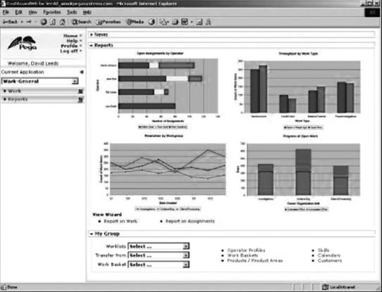 inefficient stepsalso helps process engineers and business operations people spot continuous improvements. The dashboard might reveal, for example, that a particular process path has not been run for the past five years, suggesting a redesign in which the path is eliminated and the staff that participates in it reduced or reassigned. The curious science of process mining formalizes this idea, specifying algorithms to discover the behavior of a process from the ordering of events in its logs. For example, if the logs show that, for a given process, activity A is always followed by B and then, in arbitrary order, C and D, we can guess that the process is designed such that A transitions sequentially to B, at which point it forks into two parallel paths headed by C and D, as shown in Figure 2-14. Figure 2-14. Process mining: guessing process flow from the event log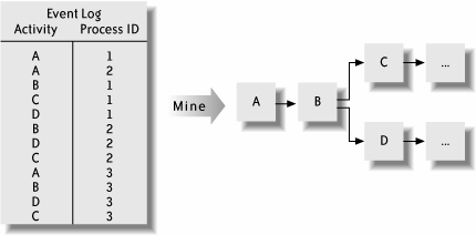 The ability to watch processes unfold "in the wild" is one of BAM's key benefits. Most processes are designed normatively, claim van der Aalst et al.[*] In other words, they are designed to behave as they should behave, but when we watch them run, we discover their actual behavior. In effect, by working backwards from the empirical runtime data, we can discover a process design that is potentially better than the one currently deployed.
2.2.6. Local View of Choreography: WS-CDL ToolkitThe most fanciful and speculative component of the architecture is the WS-CDL toolkit, which provides two tools:
There are several problematic aspects of the architecture to consider:
The good news is that BPMN is a sufficiently expressive language to capture the local participant view of a choreography. Further, BPMN's published mapping to BPEL adequately covers the key BPEL participant-related activity types: receive and invoke. In short, WS-CDL-to-BPMN-to-BPEL, when applied to choreography, is conceptually viable, although the first leg of that trip is potentially an uncomfortable ride. How does the generator work? Taking as input the choreography and the identity of the required participant, the generator scans through the choreography looking for interactions involving that participant. For each interaction, the tool generates an activity in the local process. The tool is required to handle various control constructs (sequential, conditional, parallel) and to detect and encode message correlation (e.g., correlate a response and an acknowledgement with an earlier request). Consider the following informally stated choreography: A sends request to B In parallel, B forwards request and then waits for an ack and then a response from, respectively, C and D B combines the two responses and sends to A The local process for B resembles the following: Receive request from A Do a parallel split Path 1 Send request to C Receive correlated ack from C Receive correlated response from C Path 2 Send request to D Receive correlated ack from D Receive correlated response from D Combine responses from C and D Send combined response to A As for the validator, taking as input the choreography, the identity of a participant, and the code of the participant's local process, the validator checks whether the process includes all the correct activities in the proper order. The following code for participant C is invalid because it does not include the step to send an acknowledgment: Receive request from B Send response to B |
EAN: 2147483647
Pages: 122