| The problem we have here is that when we first experience a Fibre Channel SAN, most of us think that the Fibre Channel card is in some way akin to a SCSI card. I can understand that because at the end of our SCSI card are our disks and the end of our Fibre Channel card are our disks. What we need to remember is that Fibre Channel is a link technology that supports other protocols running on top of it. In relation to disks, this means the SCSI-2 protocol is running over Fibre Channel. This is the one of the beauties of Fibre Channel, it gives us the best of both worlds ”the distances of LANs and the ease-of-use of SCSI. In some ways, I consider fibre channel as a mile-long SCSI cable (I know it can be longer than that it was a joke). In Chapter 23, we discuss Fibre Channel in more detail. Here, we are going to concentrate on deciphering device files for Fibre Channel attached disks. The most important thing to remember here is that Fibre Channel is supporting SCSI-2 protocols, so we will use SCSI-2 addressing to reference our disks. This means that the Instance number used in the device file for a disk is the Instance number of the ext_bus device to which we are connected. Let's take an example of a small SAN with two disk arrays attached to two interconnected switches: The two switches are connected together, and each HP server has a single connection to each switch. The two disk arrays have been configured with two LUNs (LUN0 = 4GB and LUN1 = 2GB) and three LUNs (LUN0 = 0GB, LUN1 = 10GB and LUN200 = 5GB), respectively. Here, we have the output from ioscan show the ext_bus interfaces for node hp1 :
root@hp1[] ioscan -fnC ext_bus Class I H/W Path Driver S/W State H/W Type Description ======================================================================== ext_bus 0 0/0/1/0 c720 CLAIMED INTERFACE SCSI C896 Ultra Wide LVD ext_bus 1 0/0/1/1 c720 CLAIMED INTERFACE SCSI C896 Ultra Wide Single-Ended ext_bus 2 0/0/2/0 c720 CLAIMED INTERFACE SCSI C87x Fast Wide Single-Ended ext_bus 3 0/0/2/1 c720 CLAIMED INTERFACE SCSI C87x Ultra Wide Single-Ended ext_bus 10 0/2/0/0.1.1.0.0 fcparray CLAIMED INTERFACE FCP Array Interface ext_bus 12 0/2/0/0.1.1.255.0 fcpdev CLAIMED INTERFACE FCP Device Interface ext_bus 14 0/2/0/0.2.1.0.0 fcparray CLAIMED INTERFACE FCP Array Interface ext_bus 15 0/2/0/0.2.1.0.1 fcparray CLAIMED INTERFACE FCP Array Interface ext_bus 17 0/2/0/0.2.1.255.0 fcpdev CLAIMED INTERFACE FCP Device Interface ext_bus 18 0/2/0/0.2.2.0.0 fcparray CLAIMED INTERFACE FCP Array Interface ext_bus 20 0/2/0/0.2.2.0.1 fcparray CLAIMED INTERFACE FCP Array Interface ext_bus 21 0/2/0/0.2.2.255.0 fcpdev CLAIMED INTERFACE FCP Device Interface ext_bus 11 0/4/0/0.1.1.0.0 fcparray CLAIMED INTERFACE FCP Array Interface ext_bus 13 0/4/0/0.1.1.255.0 fcpdev CLAIMED INTERFACE FCP Device Interface ext_bus 16 0/4/0/0.2.1.0.0 fcparray CLAIMED INTERFACE FCP Array Interface ext_bus 19 0/4/0/0.2.1.0.1 fcparray CLAIMED INTERFACE FCP Array Interface ext_bus 22 0/4/0/0.2.1.255.0 fcpdev CLAIMED INTERFACE FCP Device Interface ext_bus 4 0/4/0/0.2.2.0.0 fcparray CLAIMED INTERFACE FCP Array Interface ext_bus 23 0/4/0/0.2.2.0.1 fcparray CLAIMED INTERFACE FCP Array Interface ext_bus 5 0/4/0/0.2.2.255.0 fcpdev CLAIMED INTERFACE FCP Device Interface root@hp1[]
You can see that I have underlined the ext_bus interfaces that are acting as our Array Interface ; these are this interfaces used by the SCSI protocol to communicate with LUNs configured on the disk array. The entry described as Device Interface is simply a reference for the disk array itself; it plays no part in the addressing of individual LUNs. I suppose we need to start by explaining a little about the hardware path itself. Let's take one of the addresses as an example:
0/2/0/0.1.1.0.0
The format of the hardware path can be broken into three major components :
<HBA hardware path><Port ID><SCSI address>
Let's take each part in turn : <HBA hardware path> : An HBA in the world of Fibre Channel can be thought of as an interface card: HBA = Host Bus Adapter. In this example, the hardware path is
0/2/0/0
<Port ID> : Officially this is known as the N_Port ID . For our discussion, we can simplify it to just Port ID . The Port ID identifies the end-point in our SAN closest to our disks (LUNs). No matter how many switches we have traversed to get there, the Port ID is effectively the point at which I leave the SAN and start talking to my disk device. The Port ID is a 24-bit address assigned by a switch in our SAN. The 24-bit address is broken into three components: -
A Domain (switch number) = 1 -
An Area (physical port on the switch) = 1 -
A Port (the FC-AL Loop ID hence always 0 in a switched fabric SAN) These are the next three components in our hardware path:
1.1.0
A quick word of caution. In some (older) SANs, you may see the Area in our example as being 17. The firmware in a switch has a setting known as Core Switch PID Format . When turned off, we would add 16 to the physical port number to give the Area = 17 , taking the example above. When Core Switch PID Format is turned on, we simply use the physical port number on the switch. Most new switches come with this firmware setting turned on . A SAN will fragment (switches don't talk to each other) if switches use different settings. IMPORTANT Be careful if you ask your SAN administrator to change this firmware setting on your switches. If changed, HP-UX will see a whole new set of ext_bus interfaces all with the new Area number as part of the address. This means that a whole new set of disk device files associated with these new interfaces. If the disks are LVM disks, we will need to vgexport and vgimport entire volume groups in order to use the new disk device files. You have been warned ! |
<SCSI address> : The last component in the address of my ext_bus interface is known as the Virtual SCSI Bus (VSB) address. As we mentioned previously, Fibre Channel supports SCSI-2 protocols. Trying to visualize what this last component in the address is doing, I visualize this part of the address as the end of the SCSI cable. A Virtual SCSI Bus (visualize the end of SCSI cable) can support up to 128 devices. So at the end of this particular cable could be up to 128 LUNs. This will become important later. Our example address of 0/2/0/0.1.1.0.0 can be seen in Figure 4-1 as the line near the top of the figure. The other colored lines relate to the hardware address of an ext_bus as follows in Table 4-1. Figure 4-1. A sample switched fabric SAN 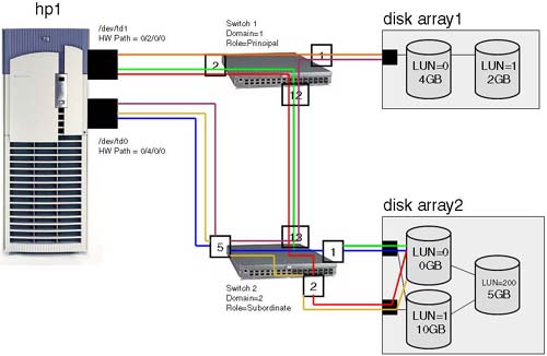
Table 4-1. Addresses of SCSI Interface | Color | H/W Path | Instance Number | | Orange | 0/2/0/0.1.1.0.0 | 10 | | Lime Green | 0/2/0/0.2.1.0.0 | 14 | | Red | 0/2/0/0.2.2.0.0 | 18 | | Burgundy/Violet | 0/4/0/0.1.2.0.0 | 11 | | Navy Blue | 0/4/0/0.2.1.0.0 | 16 | | Yellow/Gold | 0/4/0/0.2.2.0.0 | 4 |
The actual Fibre Channel cards themselves have their own Instance numbers :
root@hp1[] ioscan -fnkC fc Class I H/W Path Driver S/W State H/W Type Description ================================================================= fc 1 0/2/0/0 td CLAIMED INTERFACE HP Tachyon TL/TS Fibre Channel Mass  Storage Adapter /dev/td1 fc 0 0/4/0/0 td CLAIMED INTERFACE HP Tachyon XL2 Fibre Channel Mass Storage Adapter /dev/td0 Storage Adapter /dev/td1 fc 0 0/4/0/0 td CLAIMED INTERFACE HP Tachyon XL2 Fibre Channel Mass Storage Adapter /dev/td0
The Instance number of the Fibre Channel card plays no part in the device file name for a disk; remember that a SCSI disk is attached to an ext_bus interface. We can now talk about the address of the actual disks themselves. HP-UX hardware paths follow the SCSI-2 standard for addressing, so we use the idea of a target and SCSI logical unit number (LUN). The LUN number we see in Figure 4-1 is the LUN number assigned by the disk array. This is a common concept for disk arrays. HP-UX has to translate the LUN address assigned by the disk array into a SCSI address. If we look at the components of a SCSI address, we can start to try to work out how to convert a LUN number into a SCSI address: If we take an example of a LUN number of 20 10, there's a simple(ish) formula for calculating the SCSI target and LUN address. Here's the formula: -
Ensure that the LUN number is represented in decimal; an HP XP disk array uses hexadecimal LUN numbers while an HP VA disk array uses decimal LUN numbers. -
Divide the LUN number by 8. This gives us the SCSI target address. -
The remainder gives us the SCSI LUN. For our simple example of a LUN=20: -
LUN(on disk array) = 20 10. -
Divide 20 by 8 SCSI target = 2. -
Remainder = 4 SCSI LUN = 4. -
This would give us a complete hardware path of:
0/2/0/0 . 1 . 1 . . . 2 . 4
| Component of address | | HBA/Interface card | | Domain (=switch number) | | Area (=physical port number) | | Port (always 0 in a switched fabric) | | Virtual SCSI Bus | | SCSI target | | SCSI LUN |
The problem we've got here is that LUN numbers assigned by disk arrays can exceed 128! This poses an interesting problem for HP-UX. The way we get around that is simply to increase the Virtual SCSI Bus address every time we go beyond a multiple of 128. This goes to explain the two ext_bus we can see in the ioscan output above:
ext_bus 15 0/2/0/0.2.1.0.1 fcparray CLAIMED INTERFACE FCP Array Interface ext_bus 20 0/2/0/0.2.2.0.1 fcparray CLAIMED INTERFACE FCP Array Interface ext_bus 19 0/4/0/0.2.1.0.1 fcparray CLAIMED INTERFACE FCP Array Interface ext_bus 23 0/4/0/0.2.2.0.1 fcparray CLAIMED INTERFACE FCP Array Interface
The original ext_bus interfaces ran out of address space because we have a LUN number of 200 on our disk array. HP-UX will create additional ext_bus interfaces by increasing the Virtual SCSI Bus address by 1. These new interfaces are assigned their own Instance numbers. The Virtual SCSI Bus address is a 4-bit value, so we can support 16 VSB interfaces x 128 LUNS per VSB = 2048 LUNs per physical Fibre Channel card. This has a bearing on our formula for calculating our SCSI target and SCSI LUN address. We now have to accommodate the Virtual SCSI Bus in our formula. Here goes: -
Ensure that the LUN number is represented in decimal; an HP XP disk array uses hexadecimal LUN numbers while an HP VA disk array uses decimal LUN numbers. -
Virtual SCSI Bus starts at address 0. -
If LUN number is < 128 10, go to step 7, below. -
Increment Virtual SCSI Bus by 1 10 . -
Subtract 128 10 from the LUN number. -
If LUN number is still greater than 128 10, go back to step 4 above. -
Divide the LUN number by 8. This gives us the SCSI target address. -
The remainder gives us the SCSI LUN. In our SAN, we have a LUN = 200. Let's work out the three components of the SCSI address: -
LUN(on disk array) = 200 10 -
-
-
-
LUN number = 200 10 “ 128 10 = 72 10 -
-
Divide 72 by 8 SCSI target = 9 -
Remainder = 0 SCSI LUN = 0 -
We can now work out how specific device files are created. Let's take an example disk array LUN=200 connected via the Fibre Channel card at H/W Path 0/2/0/0. We know the ext_bus interface can see the LUN through two ports on Switch2 (ports 1 and 2). Because we are dealing with LUN=200 which exceeds 128, we are dealing with the ext_bus interfaces which utilize a new Virtual SCSI Bus interface:
ext_bus 15 0/2/0/0.2.1.0.1 fcparray CLAIMED INTERFACE FCP Array Interface ext_bus 20 0/2/0/0.2.2.0.1 fcparray CLAIMED INTERFACE FCP Array Interface
As you can see, the Virtual SCSI Bus address has been increased by one, giving us a new interface and consequently additional Instance numbers. The Instance numbers for these two new interfaces are 15 and 20 respectively, giving device file components, c15 and c20 . From our formula, to calculate the SCSI target and SCSI LUN addresses, we now know the other two components of the device file name, t9 and d0 . Here's an extract from an ioscan that shows these disks and their associated device file names :
root@hp1[] ioscan -fnC disk Class I H/W Path Driver S/W State H/W Type Description =========================================================================== ... disk 15 0/2/0/0.2.1.0.1.9.0 sdisk CLAIMED DEVICE HP A6189A /dev/dsk/c15t9d0 /dev/rdsk/c15t9d0 ... disk 19 0/2/0/0.2.2.0.1.9.0 sdisk CLAIMED DEVICE HP A6189A /dev/dsk/c20t9d0 /dev/rdsk/c20t9d0
I must admit that this was not entirely straightforward when I first looked at it, especially when you have a server connected to a large disk array with hundreds of LUNs, each with multiple paths to it. In the example above, we have a single LUN (=200) configured on a disk array, which has four paths to it. Trying to identify it can be a long and complex task. I would remind you of the adb command we have seen earlier which read the LVM header off the beginning of the disk. This can prove very useful in identifying disks that have multiple PV links to them. IMPORTANT Understanding the importance of the N_Port ID and Virtual SCSI Bus is crucial to deciphering HP-UX hardware paths for any SAN attached devices. |
Below is the ioscan output for the node hp1 with all the paths and device files for the five LUNs in Figure 4-1:
root@hp1[] ioscan -fnC disk Class I H/W Path Driver S/W State H/W Type Description =========================================================================== disk 0 0/0/1/1.15.0 sdisk CLAIMED DEVICE HP 36.4GST336753LC /dev/dsk/c1t15d0 /dev/rdsk/c1t15d0 disk 1 0/0/2/1.15.0 sdisk CLAIMED DEVICE HP 36.4GST336753LC /dev/dsk/c3t15d0 /dev/rdsk/c3t15d0 disk 20 0/2/0/0.1.1.0.0.0.0 sdisk CLAIMED DEVICE HP A6188A /dev/dsk/c10t0d0 /dev/rdsk/c10t0d0 disk 21 0/2/0/0.1.1.0.0.0.1 sdisk CLAIMED DEVICE HP A6188A /dev/dsk/c10t0d1 /dev/rdsk/c10t0d1 disk 9 0/2/0/0.2.1.0.0.0.0 sdisk CLAIMED DEVICE HP A6189A /dev/dsk/c14t0d0 /dev/rdsk/c14t0d0 disk 10 0/2/0/0.2.1.0.0.0.1 sdisk CLAIMED DEVICE HP A6189A /dev/dsk/c14t0d1 /dev/rdsk/c14t0d1 disk 15 0/2/0/0.2.1.0.1.9.0 sdisk CLAIMED DEVICE HP A6189A /dev/dsk/c15t9d0 /dev/rdsk/c15t9d0 disk 16 0/2/0/0.2.2.0.0.0.0 sdisk CLAIMED DEVICE HP A6189A /dev/dsk/c18t0d0 /dev/rdsk/c18t0d0 disk 17 0/2/0/0.2.2.0.0.0.1 sdisk CLAIMED DEVICE HP A6189A /dev/dsk/c18t0d1 /dev/rdsk/c18t0d1 disk 19 0/2/0/0.2.2.0.1.9.0 sdisk CLAIMED DEVICE HP A6189A /dev/dsk/c20t9d0 /dev/rdsk/c20t9d0 disk 11 0/4/0/0.1.1.0.0.0.0 sdisk CLAIMED DEVICE HP A6188A /dev/dsk/c11t0d0 /dev/rdsk/c11t0d0 disk 12 0/4/0/0.1.1.0.0.0.1 sdisk CLAIMED DEVICE HP A6188A /dev/dsk/c11t0d1 /dev/rdsk/c11t0d1 disk 13 0/4/0/0.2.1.0.0.0.0 sdisk CLAIMED DEVICE HP A6189A /dev/dsk/c16t0d0 /dev/rdsk/c16t0d0 disk 14 0/4/0/0.2.1.0.0.0.1 sdisk CLAIMED DEVICE HP A6189A /dev/dsk/c16t0d1 /dev/rdsk/c16t0d1 disk 18 0/4/0/0.2.1.0.1.9.0 sdisk CLAIMED DEVICE HP A6189A /dev/dsk/c19t9d0 /dev/rdsk/c19t9d0 disk 2 0/4/0/0.2.2.0.0.0.0 sdisk CLAIMED DEVICE HP A6189A /dev/dsk/c4t0d0 /dev/rdsk/c4t0d0 disk 3 0/4/0/0.2.2.0.0.0.1 sdisk CLAIMED DEVICE HP A6189A /dev/dsk/c4t0d1 /dev/rdsk/c4t0d1 disk 22 0/4/0/0.2.2.0.1.9.0 sdisk CLAIMED DEVICE HP A6189A /dev/dsk/c23t9d0 /dev/rdsk/c23t9d0 root@hp1[]
This should give you some examples to try to work out which disk Interface number is associated with each LUN, e.g., disk Interface = 22 (H/W Path = 0/4/0/0.2.2.0.1.9.0) is LUN 200 connected via /dev/td0 through the SAN via Switch2, port 2. |