Troubleshooting NAS WAN Links
| A NAS is the key piece of equipment that accepts incoming calls, authenticates the caller, and routes traffic for each call. The NAS is connected to the telephone company cloud by using a variety of leased lines that range from Basic Rate Interfaces (BRIs) to digital service 3s (DS3s). Typical design solutions include T1s and Primary Rate Interfaces (PRIs), which is why more detailed explanations about troubleshooting them are included in this section. Troubleshooting T1 CircuitsWhen you notice a problem with a T1 line, it's recommended that you start troubleshooting with the core end to determine where the problem exists. Start with the physical layer first. Controller and Line StatusStart with the physical condition and integrity of the T1 line. Always check the status of the T1 controllers and verify that you do not receive any errors. The command that displays the status is show controllers t1 , as shown in Example 7-1. Example 7-1. Output of the Command show controllers t15300-dial# show controllers t1 0 ! The circuit is up according to the next line: T1 0 is up. Applique type is Channelized T1 ! Cable length is shown next. If the circuit is not long, it needs to ! be configured differently: Cablelength is long gain36 0db Description: T1 with Pacific Bell. ! Alarms are shown in the next line. ! If an alarm exists, there is a major problem in the circuit: No alarms detected. Version info of slot 0: HW: 1, PLD Rev: 11 Framer Version: 0x8 Manufacture Cookie Info: EEPROM Type 0x0001, EEPROM Version 0x01, Board ID 0x48, Board Hardware Version 1.0, Item Number 800-3883-01, Board Revision A0, Serial Number 11692119, PLD/ISP Version 0.1, Manufacture Date 6-May-1999. Framing is ESF, Line Code is B8ZS, Clock Source is Line Secondary. ! The following 4 lines show that no errors occurred in the last 10 seconds: Data in current interval (10 seconds elapsed): 0 Line Code Violations, 0 Path Code Violations 0 Slip Secs, 0 Fr Loss Secs, 0 Line Err Secs, 0 Degraded Mins 0 Errored Secs, 0 Bursty Err Secs, 0 Severely Err Secs, 0 Unavail Secs ! The following 4 lines show a mostly clean line, but there ! were 9 Slip Seconds and 9 Errored Seconds in the last 24 hours: Total Data (last 24 hours) 0 Line Code Violations, 0 Path Code Violations, 9 Slip Secs, 0 Fr Loss Secs, 0 Line Err Secs, 0 Degraded Mins, 9 Errored Secs, 0 Bursty Err Secs, 0 Severely Err Secs, 0 Unavail Secs The first line shows line status and tells you if the T1 is either up, down, or administratively down. The first section of the output also alerts you of any alarms that are on the circuit. On the next line, you find your configured cable length. Make sure that this is configured correctly. If the observed output is not correct, the following options are available under the controller configuration mode: 5300-dial(config-controller)# cablelength { long [ gain26 gain36 ] [ 0db -7.5db -15db -22.5db ] short [ 133 266 399 533 655 ]} Cable length is defined as either long or short with long being anything over 655 feet in length. Length is the distance of the entire circuit from the closest repeater or switch to the NAS. In most cases, the closest repeater is not local, so you use the default long with a gain or a boost of 36 decibels ( gain36 ). For shorter long cable lengths, the signal is stronger and you might only need gain26 . The second part of defining a long cable length is transmitting attenuation. The default is 0db , which is the strongest transmit signal. If the circuit provider tells you that your signal is too strong, you can lower the transmit signal by using 7.5db, -15db , or 22db . A short cable length is defined in distance by feet from the NAS and closest repeater. You use the value of 133 for distances that range from 1 foot to 133 feet. The value of 266 is for distances that range from 134 to 266 feet. For distances of 267 to 399 feet, use 399. Use 533 for distances from 400 to 533. Finally, use 655 for anything between 534 and 655 feet in length. NOTE In modular routers (7200, 1600, and 1700 series), the command show service-module serial slot/port provides detailed information about the condition of the line. Examples of this command are included in Chapter 17, "Frame Relay Troubleshooting." Loopback FeaturesIf you have difficulty with any of Cisco's DS1 adapters or network modules with an internal CSU, you can troubleshoot by using the loopback command. The three main loopback modes that are configurable are diagnostic, local, and remote. Local loopback can be configured as either line or payload. Remote loopback can be configured as in- band bit-oriented code (IBOC) or Extended Superframe (ESF). Specify the loopback format using one of the following controller configuration commands: 5300-dial(config-controller)# loopback [ diagnostic local remote ] 5300-dial(config-controller)# loopback [ local { payload line }] 5300-dial(config-controller)# loopback [ remote { esf line iboc esf paylaod }] Check Bit Errors with a Bit Error Rate TesterA bit error rate tester (BERT) alerts you of any issues on the line. Although a circuit can be operational and passing data, some data might be flawed, which can be detected by using a BERT. A BERT is not an available option on every piece of Cisco hardware. If the option is not available, the proper way to perform this test is to put a tester directly on the circuit. To use a BERT to check for bit errors, if the router supports it, use the following controller configuration command: 5300-dial(config-controller)# bert pattern test pattern interval minutes The available options for test pattern are the following:
A further explanation of the most commonly used BERT test patterns include the following:
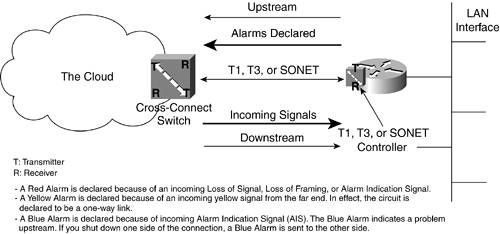
The minutes argument can be 1-14400, which designates the time that the BERT runs. BERT testing can only be done over a framed T1 signal. The test cannot run if the T1 is in an alarm state where "Receiver has loss of frame (or signal)." Additionally, it can only be run on one port at a time. Physical Layer AlarmsThe alarm section of the output from show controllers t1 is important as it tells you what type of problem might be present on the line. The presence of any alarm indicates a serious problem on the line (see Figure 7-1 and Table 7-1). In Figure 7-1, each WAN link is represented by a pair of cross-connected receivers and transmitters. Figure 7-1. A Functional Model of Physical Layer Alarm Messages When you have a T1 in an alarm state, verify that the framing and linecoding parameters are configured correctly. A common message in the alarm field is "receiver has loss of frame." Some routers also report a loss of frame (LOF) even when it should be a loss of signal (LOS). Therefore, ensure whenever you receive these errors that the T1 signal is present and the framing is correct. There are three types of alarms:
TIP Always verify the framing and T1 signal when troubleshooting. NOTE Regardless of the leased line connection that you are troubleshooting, whether a T1, T3, or Synchronous Optical Network (SONET), the alarm signals and their interpretations remain the same. The alarm states are always based on the presence or lack of signals or certain patterns. This is why the alarm states in this section apply to all circuits in the book. Linecode ViolationsThese violations occur when either a bipolar violation (BPV) or excessive zero error event is present. BPVs are inserted as a means of synchronizing circuits with bipolar 8-zero substitution (B8ZS) linecoding. Linecode errors occur when BPVs that are not used for synchronization are received. Excessive zero errors occur when eight or more 0s in a row are received on a circuit where alternate mark inversion (AMI) linecoding is being used. The errors might occur because of an AMI/B8ZS configuration problem or there might be points along the transmission path that do not have all the linecoding parameters set correctly. Pathcode ViolationsTwo examples for pathcode violations are frame synchronization errors for SF and cyclic redundancy check (CRC) errors for ESF. Typically, both pathcode violations and linecode violations are present simultaneously , so always that verify the linecoding is correct. Some smartjacks (and mux equipment) might need to be specifically configured for AMI/B8ZS because of problems with automatic linecode detection. Be aware that some amount of errors on your T1 can occur because of impulse noise; therefore, the errors might appear only a few times a day and the effects might be miniscule. Slip SecondsThe presence of slips on a T1 line indicates a clocking problem. The network provides the clocking with which the customer premises equipment (CPE) must synchronize. If you see slips on the line, verify that you are deriving your clocking from the telephone company (telco) (clock source line). It is possible that only one side of the T1 is experiencing errors, so contact the provider to ensure that they are not seeing errors on their side of the circuit. T1 ErrorsRFC 1232 defines the managed objects for the DS1 interface type and standardizes the DS1 terminology and descriptions of error conditions on a T1 or E1 circuit. Table 7-1 shows the RFC 1232 categories, errors, and their descriptions. Table 7-1. RFC 1232 Categories, Errors, and Their Descriptions
Troubleshooting PRI CircuitsA PRI is actually an ISDN connection that uses a type of signaling to channelize a T1 without robbing signaling bits from each channel; instead, the signaling is done on the last (24 th ) channel. The first step in troubleshooting problems with a PRI is to use the show isdn status command as shown in Example 7-2. Example 7-2. Output of show isdn status 5300-dialin# show isdn status Global ISDN Switchtype = primary-5ess ISDN Serial0:23 interface dsl 0, interface ISDN Switchtype = primary-5ess Layer 1 Status: ACTIVE Layer 2 Status: TEI = 0, Ces = 1, SAPI = 0, State = MULTIPLE_FRAME_ESTABLISHED Layer 3 Status: 0 Active Layer 3 Call(s) <output omitted> The following sections explain this output. Layer 1 StatusThe Layer 1 status portion of the output shows whether the T1 access circuit that the PRI signaling rides on is up or not. If it is not in an active state, go to the beginning of this chapter and troubleshoot the T1 portion of the circuit first. Layer 2 StatusIf the Layer 2 state does not show MULTIPLE_FRAME_ESTABLISHED, check the T1 circuit for incrementing errors and treat this situation as any T1 problem. More information about troubleshooting measures is covered in the section, "Troubleshooting T1 Circuits." If the T1 checks out okay, verify that the ISDN switch type and PRI group time slots were set up the same as the circuit was provisioned. Then check the serial interface associated with the PRI by using the command show interface serial x :23 , where X is the associated T1 port number. A sample output is shown in Example 7-3. Example 7-3. Output of show interface serial 0:23 S5200-dialin> show interface serial 0:23 Serial2:23 is up, line protocol is up (spoofing) Hardware is DSX1 MTU 1500 bytes, BW 64 Kbit, DLY 20000 usec, reliability 128/255, txload 1/255, rxload 1/255 Encapsulation HDLC, loopback not set DTR is pulsed for 1 seconds on reset Last input 00:00:20, output never, output hang never Last clearing of "show interface" counters never Input queue: 0/75/0/0 (size/max/drops/flushes); Total output drops: 0 <output omitted>e Verify that the D channel is up and not in a loopback state. If the state of Layer 2 is still not MULTIPLE_FRAME_ESTABLISHED, you need to call your service provider. However, if you receive this message but you are still experiencing problems, turn on ISDN Q921 debugs. After using debug isdn q921 and show debug , ensure that the output is similar to that in Example 7-4. Example 7-4. Output of show debug Indicates That debug isdn q921 Is On 5300-dialin# show debug ISDN: ISDN Q921 packets debugging is on ISDN Q921 packets debug DSLs. (On/Off/No DSL:1/0/-) DSL 0 --> 7 1 1 1 1 1 1 1 1 If you are not directly connected to the console port, you have to enable terminal monitor to see the output from debug commands. Also, verify that the only activity you see is similar to that in Example 7-5. Example 7-5. Debug Output Showing ISDN q921 Activity 5300-dialin# terminal monitor Jan 6 03:44:01.653: ISDN Se0:23: RX <- RRf sapi = 0 tei = 0 nr = 4 Jan 6 03:44:05.669: ISDN Se1:23: TX -> RRp sapi = 0 tei = 0 nr = 113 Jan 6 03:44:05.677: ISDN Se1:23: RX <- RRf sapi = 0 tei = 0 nr = 1 Jan 6 03:44:14.981: ISDN Se2:23: TX -> RRp sapi = 0 tei = 0 nr = 0 Jan 6 03:44:14.989: ISDN Se2:23: RX <- RRf sapi = 0 tei = 0 nr = 0 Jan 6 03:44:16.169: ISDN Se3:23: TX -> RRp sapi = 0 tei = 0 nr = 79 Jan 6 03:44:16.185: ISDN Se3:23: RX <- RRf sapi = 0 tei = 0 nr = 79 A service access point identifier (SAPI) has a value assigned to it. This value determines the data type coming from the device at the other end. The data types are as follows :
A terminal endpoint identifier (TEI) is an address used at Layer 2 that manages individual devices that are connecting to the ISDN network. The TEI is typically dynamically negotiated with the ISDN switch. The range is from 0 to 127. The following shows what each TEI number means:
NOTE The correct TEI for PRI is always 0. If Set Asynchronous Balanced Mode Extended (SABME) messages appear, the switch-type or PRI time slots are set incorrectly. SABME messages in the debug appear as follows: Jan 6 03:45:16.185: ISDN Se0:23: TX -> SABMEp sapi = 0 tei = 0 Jan 6 03:45:16.662: ISDN Se0:23: RX <- BAD FRAME(0x00017F)Line may be looped! See Chapter 12, "ISDN BRI Troubleshooting," for additional information about the Q921 protocol. |
EAN: 2147483647
Pages: 235