Frame Relay Topologies and Congestion Control
| After a discussion about Frame Relay design parameters, an understanding of the various Frame Relay topologies becomes important. Partial-Mesh and Full-Mesh Frame Relay DesignsFrame Relay networks provide several virtual circuits that form the basis for connections between stations (routers) that are attached to it. The resulting set of interconnected devices form a private Frame Relay group. These groups can be either fully interconnected with a complete mesh of virtual circuits, or only partially interconnected. In either case, each virtual circuit is uniquely identified at each Frame Relay interface by a DLCI. From an architectural point of view, a Frame Relay topology supports both partial-mesh and full-mesh structures. Because of the permanent nature of the connections, partial-mesh structures contain physical connections to some sites but not to all, thus creating an any-to-some structure. It becomes obvious that a fully meshed structure requires more resources because an any-to-any connection requires n number of sites to be connected to each other. This number can be calculated by using the following formula:
NOTE These topologies might exist not only on the service provider side, but in enterprises that use Frame Relay as a private network solution. Regardless of the Frame Relay network topology, from an enterprise standpoint, two main configurable connections exist to the Frame Relay network: point-to-point and point-to-multipont configurations, which are addressed in detail in Chapter 16. User and Frame Relay Switch Operations Under CongestionThe existence of virtual circuits and statistical multiplexing in Frame Relay requires sophisticated methods to deal with congestion. The Frame Relay specifications provide guidelines and rules on how the user should react to forward explicit congestion notifications (FECNs) and backward explicit congestion notifications (BECNs). The Frame Relay switch at the ingress UNI must exercise caution in the amount of traffic that it permits to enter the network. To prevent severe congestion, you need to implement measures not only at the UNI, but at the switch's ingress point, which should know when to implement rate adoption control. The software at the ingress point should be informed and fast enough to implement a remedy before the traffic load becomes a problem. There are no formal rules for the number of buffers, traffic, and throughput; however, the unofficial rule is the smaller the queue, the lower the delays and better response time. Two main methods control congestion in Frame Relay networks using explicit notification:
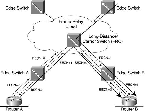
NOTE Cisco uses Enhanced LMI (ELMI). Its usage is discussed in Chapter 16. Figure 15-4 is an illustration of the first method using the rate adoption algorithm. The first Frame Relay network switch (called the Frame Relay Cloud [FRC] switch) experiences congestion. For this illustration, assume that the router connected to edge switch A sends data to both edge switch B and the router connected to edge switch B through the FRC switch. Then assume that there is additional traffic coming from the Frame Relay network to edge switch B. If the FRC switch and edge switch B are connected through a T1 and, at some point, the overall traffic increases and exceeds 1.5 Mbps, the FRC switch notifies all switches of the congestion. For a short period of time, the buffers in the FRC switch overflow and the frames are dropped. This is why the FRC switch sets the FECNs and BECNs to 1, in the manner shown in the figure. When the FRC switch reaches a certain threshold, it sets FECN = 1 in the frames that are coming from edge switch A and that are forwarded by the FRC switch to edge switch B. At the same time, the FRC switch sets BECN = 1 in the frames that are transmitted from edge switch B to edge switch A to identify the network that is experiencing congestion in the opposite direction. Figure 15-4. The Frame Relay Congestion Mechanism and Use of FECNs and BECNs
There is no standard criteria for setting BECNs and FECNs. It is obvious that different providers can choose different criteria to set up these bits. In most cases, router A lowers the transmission rate if the incoming messages contain BECN = 1. American National Standards Institute (ANSI) Annex A in T1.618 defines guidelines for using BECNs and FECNs by the user and the network. The FRC switch does not set the FECNs and BECNs directly. Instead, the FRC switch generates a CLLM to edge switches A and B, and these switches then decide to either set BECNs or FECNs or to generate another CLLM message to routers A and B. The CLLM messages are incompatible with the initial LMI specification because DLCI 1023 is used, but they are compatible with the Annex D specification. Congestion and WindowingUsing windowing to manage congestion is suggested in the book ISDN and SS7: Architectures for Digital Signaling Networks by Ulysses D. Black. The basic approach resembles the windowing mechanism in the TCP/IP stack, but combines the FECNs and BECNs with the sliding window technique. Unlike TCP, the sliding window technique reduces and increases the size of the window by a factor of 0.125, depending on the network conditions. In Cisco routers, windowing is configurable by parameter K, where K is a maximum number of I-frames that are either outstanding for transmission or transmitted but not acknowledged. The value of K ranges from 1 to 127 frames, with a default of 7. The calculations are based on 2 to the exponent n, where if n = 3, the enumeration of windows is from 0 to 7. Frame Relay Performance CriteriaThe design of Frame Relay requires setting objectives for the future network design, when conducting capacity planning, and developing the ability to measure performance using different criteria. Section 4 of T1.606 contains several definitions of Frame Relay performance parameters. The following sections summarize these performance parameters. ThroughputThe term throughput is defined as the number of protocol data units (PDUs) successfully transferred (FCS indicates success) in one direction, per a predefined time period (measurement interval) over a virtual connection. For this definition, the PDU is considered to be all data between the flags of the Frame Relay frame (see Figure 14-4). Transit DelayThe transit delay is a measurement of the time it takes to send a frame across the link between two points (DCE, Frame Relay access device (FRAD), router). The delay is a function of the access rate of the link, the distance, and the size of the frame. A rough estimate can be obtained by using the following equation:
Transit delay is measured between boundaries, which can be between two adjacent DCEs, two networks, and so forth. Based on the boundary, the measurement starts when the first bit of the PDU leaves the source (t1), and ends when the last bit of the PDU crosses the other party's boundary (t2). The transit delay can be measured by the following equation:
The virtual circuit transit delay is the sum of all delays across all boundaries of the virtual connection. Residual Error RateResidual error rate (RER) is synonymous with the undetected error ratio of the number of bits incorrectly received and undetected to the total number of bits sent. RER is measured through the exchange of Frame Relay service data units (SDUs), or FSDUs. This measurement can be calculated from the following formula:
RER is an important component when considering future use of bandwidth demand. The future design must address these parameters when evaluating the service offerings from different providers. At the same time, RER must be correlated with the user's actual throughput and CIR. If the user constantly exceeds the CIR agreement, a high RER is expected. Conversely, if the design parameters are not exceeded, a lower RER is expected. Other Performance ParametersThe following parameters are defined by the ITU-T, and are referred to as quality of service (QoS) parameters that affect network performance:
|
EAN: 2147483647
Pages: 235