4.2 Storage Area Networks
|
| < Day Day Up > |
|
Essentially, a SAN is a specialized network that enables fast, reliable access among servers and external or independent storage resources, regardless of physical location. Fibre Channel or Gigabit Ethernet links can provide high-speed transfers of data between systems distributed within a building, campus, or metropolitan area. When dense wave division multiplexed (DWDM) fiber is used, the individual wavelengths provide enough bandwidth to support any mix of Gigabit Ethernet, Fibre Channel, and enterprise systems connection (ESCON) for IBM data center connectivity, as well as synchronous optical network (SONET) traffic.
For longer distances, ATM and IP technologies can be used to transport data over the WAN (see Figure 4.2). ATM would be adept at connecting heterogeneous storage resources over the wide area, since it slices and dices different protocol traffic into standardized packets called “cells” for high-speed, jitter-free transmission between distributed storage nodes. With ATM, data availability can be maintained through integral quality of service (QoS) mechanisms that give such traffic higher priority over routine traffic. Data integrity can be maintained through the use of TCP/IP over ATM, in which case TCP handles retransmission requests for errored or missing IP frames. Proprietary mechanisms can be used to ensure data integrity. Bandwidth can even be reserved, so that storage updates occur during non-peak or non-business hours, when more bandwidth is available.
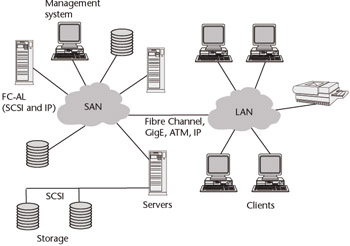
Figure 4.2: A simple SAN spanning the WAN under the supervision of a centralized management system. The access links at each location can be multiples of T1 at 1.544 Mbps (NxT1), a T3 at 45 Mbps or an optical carrier link at 155 Mbps (OC-3). Carrier-provided Ethernet services between 10 Mbps and 1 Gbps can be used as well.
In a SAN, a storage device is not the exclusive property of any one server. Rather, storage devices are shared among all networked servers as peer resources. Just as a LAN can be used to connect clients to servers, a SAN can be used to connect servers to storage, servers to each other, and storage to storage for load balancing and protection.
4.2.1 SAN Advantages
Redundancy is an inherent part of the SAN architecture, making for high availability. The “pluggable” nature of SAN resources—storage, nodes, and clients— enables much easier scalability, while preserving ubiquitous data access. And under centralized management, there is more efficiency in carrying out tasks such as optimization, reconfiguration, and backup/restore operations. While these advantages are somewhat generic and readily apply to networking in general, they are fairly new to data storage environments where different operating systems and multi-vendor products must coexist.
SANs are particularly useful for backups. Previously, there were only two choices: either a tape drive had to be installed on every server and someone went around changing the tapes, or a backup server was created and the data moved across the network, which consumed bandwidth. Performing backup over the LAN can be excruciatingly disruptive and slow. A daily backup can suddenly introduce gigabytes of data into the normal LAN traffic. With SANs, organizations can have the best of both worlds: high-speed backups managed from a central location.
Instead of dedicating a specific kind of storage to one or more servers, a SAN allows different kinds of storage—mainframe disk, tape, and RAID—to be shared by different kinds of servers, such as Windows NT/2000, UNIX, and OS/390. With this shared capacity, organizations can acquire, deploy, and use storage devices more efficiently and cost-effectively. SANs also let users with heterogeneous storage platforms use all available storage resources. This means that within a SAN, users can back up or archive data from different servers to the same storage system. They can also allow stored information to be accessed by all servers, create and store a mirror image of data as it is created, and share data between different environments.
By decoupling storage from computers, workstations, and servers, and taking storage traffic off the operations network, organizations gain a high-performance storage network and improve the performance of the LAN. Of course, each network—SAN and LAN—is still subject to resource contention from among its respective users, but the performance of both is improved by keeping them separate. In effect, the SAN does in a network environment what traditionally has been done in a back-end I/O environment between a server and its own storage subsystem. The result is high speed, high availability, and high reliability.
While a physically separate network to handle storage and archival traffic is often desirable, it is by no means necessary. This is because the SAN can function as a virtual subnet that operates on a shared network infrastructure. For this to work, however, different priorities or classes of service must be established so that all users and applications obtain their fair share of available bandwidth. Both Fibre Channel and ATM provide the means to set different classes of service, and this capability can be added to IP for a more economical approach to storage area networking.
SANs also promise easier and less-expensive network administration. Today, administrative functions are labor-intensive and time-consuming, and IT organizations typically have to replicate management tools across multiple server environments. With a SAN, only one set of tools is needed, which eliminates the need for their replication and associated costs. While these advantages apply to networks in general, they are relatively new for data storage environments.
All of this makes SANs highly suited for data-intensive environments like those used for video editing, prepress, on-line transaction processing (OLTP), data warehousing, storage management, and server clustering applications. For the enterprise, SANs constitute an essential ingredient in any business continuity plan.
4.2.2 SAN Evolution
SANs have existed for years in the mainframe environment in the form of ESCON. In mid-range environments, the high-speed data connection was primarily small computer system interface (SCSI)—a point-to-point connection that is severely limited in terms of the number of connected devices it can support, as well as the distance between devices.
An alternative to network attached storage (NAS) was developed in 1997 by Michael Peterson, president of Strategic Research in Santa Barbara, Calif. He believed NAS was too limiting because it relied on network protocols that did not guarantee delivery. He proposed SANs that could be interconnected using network protocols such as Ethernet, and that the storage devices themselves could be linked via non-network protocols.
According to Peterson, SANs have three major components: the interfaces, including SCSI, IBM Serial Storage Architecture (SSA) or Fibre Channel; interconnects, such as extenders, multiplexers, hubs, switches, and routers; and the switching fabric. In a traditional storage environment, a server controls the storage devices and administers requests and backup. With a SAN, instead of being involved in the storage process, the server simply monitors it. By optimizing the box at the head of the SAN to do only file transfers, users are able to get much higher transfer rates. This is where Fibre Channel comes in.
Using Fibre Channel as the connection between storage devices increases the distance options. While traditional SCSI allows only a 25-meter (about 82 feet) distance between machines and Ultra2 SCSI allows only a 12-meter distance (about 40 feet), Fibre Channel supports spans of 10 km (about 6.2 miles), making it suited to building campus-wide storage networks. SCSI can only connect up to 16 devices, whereas Fibre Channel can link as many as 126. By combining LAN networking models with the core building blocks of server performance and mass storage capacity, SAN eliminates the bandwidth bottlenecks and scalability limitations imposed by previous SCSI bus-based architectures.
More recently, vendors have pushed the speed of Fibre Channel from 1 Gbps to 2 Gbps and increased the distance beyond the original 6.2 miles to about 75 miles. As the SAN concept has evolved, it has moved beyond association with any single technology. In fact, just as LANs and WANs use a diverse mix of technologies, so can SANs. This mix can include FDDI, ATM, and IBM’s SSA, as well as Fibre Channel. More recently, SONET and DWDM have been added to the mix to extend the operating range of storage networks. Infiniband has come along to offer massive amounts of bandwidth and improvements in I/O performance. And now that broadband connections are becoming more available, even the TCP/IP suite of Internet protocols is being used for a more economic implementation of storage networks.
Although early implementations of SANs have been local or campus-based, there is no technological reason why they cannot be extended much farther with such proven technologies such as SONET and ATM. With its 50-ms recovery time, SONET also offers the benefit of extremely high resiliency. This capability is also available with some DWDM systems. In either case, data travels to its destination in opposite directions over a dual-ring architecture (see Figure 4.3). If one of the fibers is cut or a node fails, protection mechanisms kick in to ensure that data gets to its destination with little or no loss. ATM’s QoS capabilities and priority queuing techniques allow the SAN to be extended over a much wider area—perhaps globally—with little or no performance fatigue. Running TCP/IP over SONET/DWDM or ATM provides for the retransmission of errored or missing frames, ensuring data integrity.
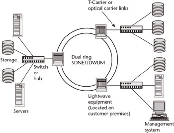
Figure 4.3: For metro-area SANs, SONET/DWDM systems offer the highest resiliency of any transport technology. Even if a fiber gets cut or a node on the ring fails, data gets to its proper destination with very little loss. Data integrity is ensured using higher-level protocols like TCP/IP.
Infiniband is emerging as a viable high-speed interconnect technology that provides the basis for an I/O fabric designed to increase the aggregate data rate between servers and storage devices over copper or fiber media at distances of up to 17 meters and 10 km, respectively. This point-to-point linking technology is intended to replace current interconnect technologies such as the peripheral component interconnect (PCI) and its successor, PCI-X. The I/O fabric of the Infiniband architecture takes on a role similar to that of the traditional mainframe-based channel architecture, which uses point-to-point cabling to maximize overall I/O throughput by handling multiple I/O streams simultaneously. With Infiniband’s ability to act as a server’s I/O external from the server chassis, independent scaling of processing and I/O capacity is possible, creating more flexibility for data center managers. Unlike today’s servers, which contain a defined number of I/O connections per box, Infiniband servers can share I/O resources across the fabric.
PCI supports up to 133 Mbps, providing shared bandwidth of up to 566 Mbps, while PCI-X permits a maximum bandwidth of 1 Gbps. While Fibre Channel offers bandwidth up to 2 Gbps, Infiniband uses a 2.5-Gbps wire-speed connection with multi-wire link widths. With a four-wire link width, for example, Infiniband offers 10 Gbps of bandwidth. The move to Infiniband means that I/O subsystems need no longer be the bottleneck to improving overall data throughput for server systems.
Infiniband technology works by connecting host-channel adapters to target channel adapters. The host-channel adapters tend to be located near the servers’ CPUs and memory, while the target channel adapters tend to be located near the systems’ storage and peripherals. A switch located between the two types of adapters directs data packets to the appropriate destination based on information that is bundled into the data packets themselves.
The connection between the host-channel and target-channel adapters is the Infiniband switch, which allows the links to create a uniform fabric environment. One of the key features of this switch is that it allows data to be managed based on variables such as service level agreements and a destination identifier. In addition, Infiniband devices support both packet and connection protocols to provide a seamless transition between the SAN and external networks. Infiniband fabrics will be managed via Infiniband consoles, and Infiniband fabric management is expected to snap into existing enterprise management solutions.
Infiniband will coexist with the wide variety of existing I/O standards that are already widely deployed in user sites. The key advantage of the Infiniband architecture, however, is that it offers a new approach to I/O efficiency. Specifically, it replaces the traditional system bus with an I/O fabric that supports parallel data transfers along multiple I/O links. Furthermore, the Infiniband architecture offloads CPU cycles for I/O processing, delivers faster memory pipes and higher aggregate data-transfer rates, and reduces management overhead for the server system.
Infiniband started out as a proprietary technology, with a formal specification issued in 2000, and may become the de facto standard for communication between processing nodes and I/O devices, as well as for interprocessor communication. More than 100 companies are supporting the technology through the Infiniband Trade Association.
4.2.3 SAN Components
Several components are required to implement a Fibre Channel SAN. A Fibre Channel adapter is installed in each server. These are connected via the server’s personal computer interface (PCI) bus to the server’s operating system and applications. Because Fibre Channel’s transport-level protocol wraps easily around SCSI frames, the adapter appears to be an SCSI device. The adapters are connected to a single Fibre Channel hub, running over fiber-optic cable or copper coaxial cable. Category 5, the UTP wiring rated for 10/100/1,000 Mbps Fast Ethernet, can also be used.
A LAN-free backup architecture may include some type of automated tape library that attaches to the hub via Fibre Channel. This machine typically includes a mechanism capable of feeding data to multiple tape drives and may be bundled with a front-end Fibre Channel controller. Existing SCSI-based tape drives can be used through the addition of a Fibre Channel-to-SCSI bridge.
Storage management software running in the servers performs contention management by communicating with other servers via a control protocol to synchronize access to the tape library. The control protocol maintains a master index and uses data maps and time stamps to establish the server-to-hub connections. At this writing, control protocols and other management elements are specific to the software vendors. Eventually, the storage industry will standardize on CIM-SAN-1, which has been approved by the Storage Network Industry Association (SNIA) and is supported by key vendors (see Section 4.2.8).
From the hub, a standard Fibre Channel protocol, Fibre Channel-Arbitrated Loop (FC-AL), functions similarly to token ring to ensure collision-free data transfers to the storage devices. The hub also contains an embedded SNMP agent for reporting events to network management software.
4.2.4 Role of Hubs and Switches
Much like Ethernet hubs in LAN environments, Fibre Channel hubs provide a degree of fault tolerance in SAN environments in addition to more convenient wiring and cable management. On a Fibre Channel-Arbitrated Loop, each node acts as a repeater for all other nodes on the loop, so if one node goes down, the entire loop goes down. For this reason, hubs are an essential source of fault isolation in Fibre Channel SANs. The hub’s port bypass functionality will automatically circumvent a problem port and avoid most faults. Stations can be powered off or added to the loop without impacting the rest of the SAN. Storage management software is used to mediate contention and synchronize data—activities necessary for moving backup data from multiple servers to multiple storage devices.
To achieve full redundancy in a Fibre Channel SAN, two fully independent, redundant loops must be cabled. This scheme provides two independent paths for data with fully redundant hardware. Most disk drives and disk arrays targeted for high availability environments have dual ports specifically for that purpose. Wiring each loop through a hub provides higher-availability port-bypass functionality to each of the loops.
Some organizations will need multiple levels of hubs. Hubs can be cascaded up to the Fibre Channel-Arbitrated Loop limit of 126 nodes [127 nodes with a Fabric Loop (FL) or switch port]. Normally, the distance limitation between Fibre Channel hubs is 3 km. Several vendors, however, have found ways to extend the distance between hubs to 10 km, allowing organizations to link servers situated on either side of a campus, or even spanning a metropolitan area.
Hubs replace the mess of cables in the loop. This simplifies cable management, but bandwidth is still shared between all the devices. With switches, the bandwidth is no longer shared; private loops are established between pairs of devices that wish to communicate with each other. This means that every link between two devices (server or storage) has access to the full 1 Gbps or 2 Gbps of bandwidth. When a device fails or is removed from the loop, the switch bypasses the port so communication around the loop can be maintained.
Linking hubs with a switch provides complementary SAN services such as allowing departmental hubs to be connected with a backup link for higher availability. In the event that one of the primary links between departments has problems, the alternate link can be used to provide improved availability. In addition, a switch allows a longer-distance connection, up to 10 km between two nodes, which allows the SAN to span greater distances for increased disaster tolerance. The performance (concurrency) and department segmentation that are provided with a switch allow the departments to share valuable storage resources and develop common management of the storage resource.
Another type of switch in the SAN environment is the fabric switch, which used frame switching to allow up to 16 million devices to be connected to a single SAN. The fabric switch can support hundreds of switches in a cascade configuration and allow distances of more than 100 km.
4.2.5 Zoning
A key feature of a SAN is zoning, a term used to denote the division of a SAN to provide different levels of connectivity between specific hosts and devices on the network. This gives IT managers the flexibility to support the needs of different groups and technologies without compromising data security. A zone may include multiple subnets and is established by cooperative consent of the hosts or can be enforced at the switch level. In the former case, hosts are responsible for communicating with the switch to determine if they have the right to access a device. There are several ways to implement zoning: hard zones, name server zones, and broadcast zones. Defining a zone or adding or changing devices within a zone is performed via management software that comes with the SAN switch.
Hard Zones
With this method of zoning, the IT manager programs zone assignments into the flash memory of the hub or switch. This ensures that no data traffic can move between devices in different zones, making for the highest degree of security. In cases where more than one switch is assigned to the same zone, a dedicated interswitch link (ISL) guarantees the I/O bandwidth and gives the IT manager the means to balance bandwidth across all hard zones for maximum overall performance. The number of hard zones a SAN switch can support depends on manufacturer and equipment model. Each hard zone can be further subdivided via the name server, segmented loop, or broadcast zone features. This enables the larger fabric to be carved into separate fabrics for specific uses, maximizing switch port efficiency and reducing the number of switches required.
Name Server Zones
This method of zoning allows the IT manager to create zones using either switch ports or world wide names (WWNs) to assign zones. Name server zones can overlap, and all ISLs within a hard zone are available to all the name server zones, providing load balancing for maximum data throughput under heavy loads.
The easiest way to physically map all the devices to a SAN is to define a name server zone that correlates with switch ports. With this method of zoning, all devices are connected to a particular port on a specific switch. But zones based on switch ports can create other problems. First, all devices on the port must be included in the zone; second, if a device is moved from one port to another it may end up in a different zone.
With the WWN method of zoning, a device is assigned to a zone according to its unique name, giving the IT manager the flexibility to install a device, host, or storage unit anywhere within the SAN fabric. A device assigned by WWN will stay in its assigned zone regardless of the physical port that serves as its connection. This type of zoning also eases troubleshooting by allowing the IT manager to move the device at the suspect port location to another port location to verify if the problem is with the port, or if it follows the device to the other port without reconfiguring the zone.
Broadcast Zones
This method of zoning is based on traffic type. Broadcast zones are assigned to separate different types of traffic, such as network traffic (e.g., TCP/IP) from storage traffic (e.g., SCSI), in the SAN environment. By eliminating unnecessary message processing by host and storage connections, broadcast zones reduce traffic on the fabric. Broadcast zones can overlap name server zones, but not hard zones.
4.2.6 Security
Generally, a SAN has the same security needs as a file server network. Fortunately, the application server shields the SAN from end users, so there is no direct desktop access to the contents of the SAN. The application server(s) must provide the security mechanisms to prevent unauthorized access or denial of service attacks. In a heterogeneous server environment, this is a particularly difficult challenge because of the inherent difference of security levels between platforms and the administrator’s experience with server security.
If an attacker does manage to compromise a server, the entire SAN is vulnerable to intrusion, since the breached server may be used as the springboard to all of the logical storage units on the network. There are a few techniques to counter such attacks. The easiest is to use switch zoning in an intelligent way to prevent the whole SAN from being accessible to all servers. Breaking the SAN into subnets with traffic strictly partitioned between servers and storage prevents global access to the SAN.
Logical unit number (LUN) masking is another technique that can thwart an intruder. This technique is implemented on the storage servers by setting permissions for visibility and access to specific devices.
Outside the SAN itself, the IT manager must take reasonable precautions to shield the LAN from eavesdropping or “man-in-the-middle” hacks that replay or alter traffic as it traverses the LAN. This is primarily important only when the data contains sensitive financial, medical, or proprietary information. The servers running the SAN management agents would also be of particular interest to a network interloper. Physical access restrictions can play a key role in minimizing intrusions that originate from within the organization.
4.2.7 SAN Management
The basic tools needed to manage systems on a Fibre Channel fabric are available through the familiar SNMP interface. The Fibre Channel–Arbitrated Loop (FC-AL) MIB approved by the Internet Engineering Task Force (IETF) extends SNMP management capabilities to the multi-vendor SAN environment. Other vendor-specific MIBs will emerge as products are developed with new management features. Switches, hubs, and other central networking hardware provide a natural point for network management. Of course, GUI-based management systems will play a key role in managing storage networks.
One of these GUI-based management solutions comes from Tivoli Systems. The company’s Tivoli Storage Network Manager simplifies the complexity of managing information across the multiple platform and operating environments typical in a SAN. Policy-based automation and expansion capabilities help administrators ensure the availability of mission-critical applications, thereby providing higher storage resource utilization.
Once the SAN elements have been discovered, storage resources assigned, and policies established for monitoring file systems, administrators can then do the following:
-
Continually monitor all the components within the discovered SAN topology;
-
Capture data to be used for reporting on performance, capacity, and service-level planning;
-
Automatically extend supported file systems that are becoming full;
-
Receive automatic notification when file systems exceed a predetermined threshold.
Tivoli Storage Network Manager also generates SNMP traps and Tivoli Enterprise Console (TEC) events to report on all activities that it monitors. These events can then be sent to the designated management console or the designated administrator. Tivoli Storage Network Manager can also be configured to send SNMP traps or TEC events to one or more locations (see Figure 4.4). This is done by entering information in the following fields:
-
IP Address: IP address of a host or device that can receive SNMP traps.
-
Port: Port number that the host or device will use to listen for SNMP traps. The default is 162.
-
Community: Name of the community to which the SNMP host or device is assigned. The default is Public.
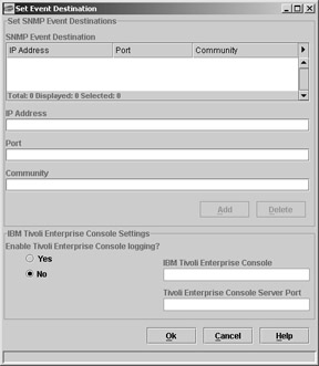
Figure 4.4: Tivoli Storage Network Manager’s event destinations screen.
Events and data from the SAN are continuously captured and processed, providing information, alerts, and notification to the administrator for problem resolution. The administrator can then launch specific SAN management software from within Tivoli Storage Network Manager to assist in problem closure.
Among the other companies that offer SAN management solutions is EMC, which offers the VisualSAN software suite. One component of the suite is Visual-SAN Network Manager, which automatically discovers, manages, and monitors multi-vendor SAN devices, generating a topology map that depicts the SAN network elements, servers, storage systems, and their interconnects.
By drilling down through the map, the administrator can view which devices and interconnects are active and which need attention. An event correlator collects and consolidates faults, events, and alerts and presents this information in real time. All events are logged and user-defined alerts are generated. The system can be configured to notify the system administrator of fault conditions via e-mail, page, or SNMP trap. This real-time alerting allows the administrator to quickly and effectively manage the entire SAN.
Performance Manager, another component of the Visual SAN software suite, is a module that monitors real-time performance of SANs and renders this data in an intuitive visual format with alert generation. The collected data is used for historical and trending analysis.
Hewlett-Packard also offers a SAN management solution. The company’s OpenView Storage Node Manager offers the following SAN management capabilities:
-
Automatic discovery of devices connected to a SAN.
-
Multidimensional graphical representations of the network.
-
Problem tracking using the topology map and other technologies.
-
Management of Fibre Channel arbitrated loop configurations, as well as fabrics.
Users are also able to set basic levels of service in the SAN and use tools such as SNMP, so that if a storage device or disk is in danger of failing, an alarm will be triggered on the OpenView screen. Also, users are able to set thresholds for storage disks and could receive a warning when the disk is approaching its data saturation point.
A relatively new trend in storage management is the ability of administrators to access NAS and SAN information through a secure Web portal, eliminating the need to jump from console to console to manage different aspects of storage. Instead, they can view all management information and initiate management actions through their browser at the portal. On logging into the portal, administrators can perform a number of critical tasks, including the following:
-
Consolidate information into an enterprise-wide view;
-
Integrate different storage management functions and applications;
-
Collect data from disparate tools and devices to provide a consistent, uniform view of the enterprise storage environment;
-
View only the information an administrator needs to know to perform a given task, such as backup or storage allocation.
Among the storage management vendors that offer such portals is Computer Associates. Its BrightStor product combines storage management access through a single portal and the ability to decouple functional storage needs from the details of storage execution and implementation. Through its instrumentation capabilities, BrightStor learns about the storage environment—configuration, data access patterns, storage utilization, and allocation. Using rules defined by the administrator, the management tool responds to changes in the storage environment, performing automatic, dynamic storage provisioning and other high-level storage management tasks without the administrator needing to know about the details of where capacity is physically located or how it is configured for a specific device.
For example, when new storage capacity in the form of a NAS device on the network or another disk array on the SAN is added to the environment, BrightStor will automatically find the new capacity and apply its policies to appropriately configure the new capacity and migrate the data volumes to it for purposes of load balancing, data protection, or performance management. It will then update the backup processes and policies to ensure the data is properly backed up in its new location.
By decoupling functional storage needs from the details of storage execution and implementation, the addition of new capacity is facilitated, since the labor-intensive task of manually configuring the storage, migrating data, and updating backup scripts is eliminated. This decoupling also enables administrators to define policies to automate storage operations and manage workflow without having to manually execute those operations and processes on diverse, individual storage systems and devices. These capabilities can dramatically increase personnel efficiencies while reducing the opportunities for potentially disastrous human error.
BrightStor instrumentation relies on agents that collect and process data from the elements of the storage management system, normalize the data, analyze it, and use it as the basis for initiating intelligent, automated actions. Two types of instrumentation agents are used. An XML-based sponsor agent collects data from applications and devices. Once a storage element has been instrumented, the agent can be redirected to serve a variety of other management needs.
A gateway agent handles data communication required to support management services, offering transport (e.g., Hypertext Transfer Protocol), providing management control, and minimizing network traffic loads. For example, an administrator may need to know the status of all backup jobs across the enterprise. Typically, this would require the administrator to launch the management console for each backup product in use. With BrightStor, however, the administrator working at the portal simply invokes a method that collects the information from instrumentation for BrightStor and numerous other storage solutions from different vendors. The information is aggregated and normalized and presented to the administrator, who can now see backup status across the enterprise at a glance. In another scenario, the administrator may want to look at disk utilization across the enterprise. Again, instead of launching management consoles for the different disk storage systems, the administrator simply invokes a method that reports capacity utilization data.
4.2.8 Management Interoperability
While standards have been developed for Fibre Channel technology, different interpretations of the standards by vendors have resulted in products that may not work together on the same network. As a result, interoperability problems still plague the SAN industry, particularly in the area of management. Many vendors are now working on standards through organizations such as the SNIA, the Distributed Management Task Force (DMTF), the Fibre Channel Industry Association (FCIA), the Fibre Alliance, and the Open System Fabric Initiative (OSFI).
SNIA’s storage management initiative started with CIM-SAN-1, an approach that manages multi-vendor SANs through a single management backbone built on the DMTF’s Common Information Model (CIM) and Web-Based Enterprise Management (WBEM) technologies. In integrating multiple management clients with storage networking devices that comprise a multi-vendor SAN configuration, CIM-SAN-1 simplifies storage management for users.
The CIM-SAN-1 provides security, locking, and discovery features for SAN management. It provides enterprises with a standard for managing devices such as disk arrays, switches, and hosts in a SAN by specifying a common model of device behavior and a common language to read and set control information. Large management vendors, including IBM, are already supporting CIM-SAN-1. IBM supports it in its SAN-wide file system and storage virtualization engine to extend the concept of SAN interoperability beyond basic system identification and monitoring to more comprehensive and efficient management capabilities. The company’s storage management software products from Tivoli are expected to integrate COM-SAN-1 as well.
The success of COM-SAN-1 resulted in SNIA’s Storage Management Initiative (SMI), which is driving the first common and interoperable management backbone for large scale, multi-vendor storage networks. Version 1.0 of the SMI specification was released for formal SNIA review in December 2002. Its development is expected to result in more powerful management applications that reduce the cost of management and allow storage networking vendors to ship management interface technology with reduced costs and faster time-to-market. SNIA members are being encouraged to join the new Storage Management Forum to accelerate the SMI program so that all storage can be managed by the SMI in 2005.
|
| < Day Day Up > |
|
EAN: 2147483647
Pages: 184