Hard Disk Drive Operation
| The basic physical construction of a hard disk drive consists of spinning disks with heads that move over the disks and store data in tracks and sectors. The heads read and write data in concentric rings called tracks, which are divided into segments called sectors, which typically store 512 bytes each (see Figure 9.2). Figure 9.2. The tracks and sectors on a disk.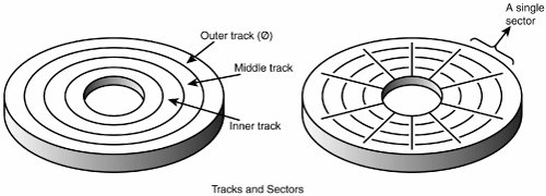 Hard disk drives usually have multiple disks, called platters, that are stacked on top of each other and spin in unison, each with two sides on which the drive stores data. Most drives have two or three platters, resulting in four or six sides, but some PC hard disks have up to 12 platters and 24 sides with 24 heads to read them (Seagate Barracuda 180). The identically aligned tracks on each side of every platter together make up a cylinder (see Figure 9.3). A hard disk drive usually has one head per platter side, with all the heads mounted on a common carrier device or rack. The heads move radially across the disk in unison; they can't move independently because they are mounted on the same carrier or rack, called an actuator. Figure 9.3. Hard disk cylinders.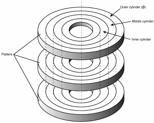 Originally, most hard disks spun at 3,600rpmapproximately 10 times faster than a floppy disk drive. For many years, 3,600rpm was pretty much a constant among hard drives. Now, however, most drives spin even faster. Although speeds can vary, modern drives typically spin the platters at either 4,200rpm; 5,400rpm; 7,200rpm; 10,000rpm; or 15,000rpm. Most standard-issue drives found in PCs today spin at 7,200rpm, with high-performance models spinning at 10,000rpm, although many less-expensive drives still spin at 5,400rpm. Some of the small 2 1/2" notebook drives run at only 4,200rpm to conserve power, and 15,000rpm drives are usually found only in very high-performance workstations or servers, where their higher prices, heat generation, and noise can be more easily dealt with. High rotational speeds combined with a fast head-positioning mechanism and more sectors per track are what make one hard disk faster overall than another. The heads in most hard disk drives do not (and should not!) touch the platters during normal operation. However, on most drives, the heads do rest on the platters when the drive is powered off. In most drives, when the drive is powered off, the heads move to the innermost cylinder, where they land on the platter surface. This is referred to as contact start stop (CSS) design. When the drive is powered on, the heads slide on the platter surface as they spin up, until a very thin cushion of air builds up between the heads and platter surface, causing the heads to lift off and remain suspended a short distance above or below the platter. If the air cushion is disturbed by a particle of dust or a shock, the head can come into contact with the platter while it is spinning at full speed. When contact with the spinning platters is forceful enough to do damage, the event is called a head crash. The result of a head crash can be anything from a few lost bytes of data to a completely ruined drive. Most drives have special lubricants on the platters and hardened surfaces that can withstand the daily "takeoffs and landings" as well as more severe abuse. Some newer drives do not use CSS design and instead use a load/unload mechanism that does not allow the heads to contact the platters, even when the drive is powered off. First used in the 2 1/2" form factor notebook or laptop drives where resistance to mechanical shock is more important, traditional load/unload mechanisms use a ramp positioned just off the outer part of the platter surface, whereas some newer designs position the ramp near the spindle. When the drive is powered off or in a power-saving mode, the heads ride up on the ramp. When powered on, the platters are allowed to come up to full speed before the heads are released down the ramp, allowing the airflow (air bearing) to prevent any head/platter contact. Because the platter assemblies are sealed and nonremovable, the track densities on the disk can be very high. Hard drives today have up to 96,000 or more tracks per inch (TPI) recorded on the media (Hitachi Travelstar 5K80). Head disk assemblies (HDAs), which contain the platters, are assembled and sealed in clean rooms under absolutely sanitary conditions. Because few companies repair HDAs, repair or replacement of the parts inside a sealed HDA can be expensive. Every hard disk ever made eventually fails. The only questions are when the failure will occur and whether your data is backed up. Caution It is strongly recommended that you do not even attempt to open a hard disk drive's HDA unless you have the equipment and expertise to make repairs inside. Most manufacturers deliberately make the HDA difficult to open to discourage the intrepid do-it-yourselfer. Opening the HDA voids the drive's warranty. Many PC users know that hard disks are fragile, and comparatively speaking, they are certainly one of the more fragile components in your PC. That being the case, it comes as somewhat of a surprise to the students in some of my PC Hardware and Troubleshooting or Data Recovery seminars when I run various hard disks with the covers removedand in some cases I've even removed and installed the covers while the drives were operating! Those drives continue to store data perfectly to this day with their lids either on or off. Of course, I do not recommend that you try this with your own drives. The Ultimate Hard Disk Drive AnalogyThere is an old analogy that compares the interaction of the heads and the medium in a typical hard disk drive as being similar in scale to a 747 Jumbo Jet flying a few feet off the ground at cruising speed (500+ mph). I have heard this analogy used repeatedly for years, and in the past I even used it myself without checking to see whether the analogy is technically accurate with respect to modern hard drives. It isn't. Perhaps the most inaccurate aspect of the 747 analogy is the use of an airplane of any type to describe the head-and-platter interaction. This analogy implies that the heads fly very low over the surface of the disk, but technically, this is not true. The heads do not fly at all in the traditional aerodynamic sense; instead, they float or ski on a cushion of air that is being dragged around by the platters. A much better analogy would use a hovercraft instead of an airplane; the action of a hovercraft much more closely emulates the action of the heads in a hard disk drive. Like a hovercraft, the drive heads rely somewhat on the shape of the bottom of the head to capture and control the cushion of air that keeps them floating over the disk. By nature, the cushion of air on which the heads float forms only in very close proximity to the platter and is often called an air bearing by those in the disk drive industry. I thought it was time to come up with a new analogy that more correctly describes the dimensions and speeds at which a hard disk drive operates today. I looked up the specifications on a specific modern hard disk drive and then magnified and rescaled all the dimensions involved by a factor of more than 300,000. For my example, I use an IBM Deskstar 75GXP drive, which is a 75GB (formatted capacity), 3 1/2" ATA (AT Attachment interface) drive. The head sliders (called pico sliders) in this drive are about 0.049" long, 0.039" wide, and 0.012" high. They float on a cushion of air about 15 nanometers (nm or billionths of a meter) over the surface of the disk while traveling at an average true speed of 53.55 miles per hour (figuring an average track diameter of about 2 1/2"). These heads read and write individual bits spaced only 2.56 micro-inches (millionths of an inch) apart, along tracks separated by only 35.27 micro-inches. The heads can move from one track to another in 8.5 milliseconds during an average seek. To create my analogy, I magnified the scale to make the head floating height equal to 5 millimeters (about 0.2"). Because 5 millimeters is about 333,333 times greater than 15 nanometers (nm), I scaled up everything else by the same amount. Magnified to such a scale, the heads in this typical hard disk would be about 1,361 feet long, 1,083 feet wide, and 333 feet high (the length and height would be about equal to the Sears Tower if it were tipped over sideways). These skyscraper-sized heads would float on a cushion of air that to scale would be only 5mm thick (about 0.2") while traveling at a speed of 17.8 million miles per hour (4,958 miles per second), all while reading data bits spaced a mere 0.85" apart on tracks separated by only 0.98 feet! The proportionate forward speed of this imaginary head is difficult to comprehend, so I'll elaborate. The diameter of the Earth at the equator is 7,926 miles, which means a circumference of about 24,900 miles. At 4,958 miles per second, this imaginary skyscraper-sized head would circle the earth once every 5 seconds (at only two-tenths of an inch over the surface)! It would also read 231.33MB in one lap around this equatorial track. There is also sideways velocity to consider. Because the average seek time of 8.5 milliseconds is defined as the time it takes to move the heads over one-third of the total tracks (about 9,241 tracks in this example), the heads could move sideways within a scale distance of 1.71 miles in that short time. This results in a scale seek velocity of more than 726,321mph, or 202 miles per second! This analogy should give you a new appreciation of the technological marvel that the modern hard disk drive actually represents. It makes the old Jumbo Jet analogy look rather pathetic (not to mention grossly inaccurate), doesn't it? Tracks and SectorsA track is a single ring of data on one side of a disk. A disk track is too large to manage data effectively as a single storage unit. Many disk tracks can store 100,000 or more bytes of data, which would be very inefficient for storing small files. For that reason, tracks are divided into several numbered divisions known as sectors. These sectors represent arc-shaped pieces of the track. Various types of disk drives split their disk tracks into different numbers of sectors, depending on the density of the tracks. For example, floppy disk formats use 836 sectors per track, although hard disks usually store data at a higher density and today can have 900 or more sectors per track physically. The sectors created by the standard formatting procedure on a PC system have a capacity of 512 bytes, which has been one constant throughout the history of the PC. One interesting phenomenon of the PC standard is that to be compatible with most older BIOSs and drivers, drives usually perform an internal translation so that they pretend to have 63 sectors per track when addressed in CHS (cylinder, head, sector) mode. The sectors on a track are numbered starting with 1, unlike the heads or cylinders that are numbered starting with 0. For example, a 1.44MB floppy disk contains 80 cylinders numbered 079 and two heads numbered 0 and 1, whereas each track on each cylinder has 18 sectors numbered 118. When a disk is formatted, the formatting program creates ID areas before and after each sector's data that the disk controller uses for sector numbering and identifying the start and end of each sector. These areas precede and follow each sector's data area and consume some of the disk's total storage capacity. This accounts for the difference between a disk's unformatted and formatted capacities. Note that most modern hard drives are sold preformatted and advertise only the formatted capacity. The unformatted capacity is usually not mentioned anymore. Another interesting development is that many new drives use what is called No-ID sector formatting, which means the sectors are recorded without ID marks before and after each sector. Therefore, more of the disk can be used for actual data. Each sector on a disk usually has a prefix portion, or header, that identifies the start of the sector and contains the sector number, as well as a suffix portion, or trailer, that contains a checksum (which helps ensure the integrity of the data contents). Many newer drives omit this header and have what is called a No-ID recording, allowing more space for actual data. With a No-ID recording, the start and end of each sector are located via predetermined clock timing. Each sector contains 512 bytes of data. The low-level formatting process typically fills the data bytes with some specific value, such as F6h (hex), or some other repeating test pattern used by the drive manufacturer. Some patterns are more difficult for the electronics on the drive to encode/decode, so these patterns are used when the manufacturer is testing the drive during initial formatting. A special test pattern might cause errors to surface that a normal data pattern would not show. This way, the manufacturer can more accurately identify marginal sectors during testing. Note The type of disk formatting discussed here is a physical or low-level format, not the high-level format you perform when you use a Windows DOS-based FORMAT program. See the section "Disk Formatting," later in this chapter, to learn about the difference between these two types of formatting. The sector headers and trailers are independent of the operating system, file system, and files stored on the drive. In addition to the headers and trailers, gaps exist within the sectors, between the sectors on each track, and between tracks, but none of these gaps contain usable data space. The gaps are created during the low-level format process when the recording is turned off momentarily. They serve the same function as having gaps of no sound between the songs recorded on a cassette tape. The prefix, suffix, and gaps account for the lost space between the unformatted capacity of a disk and the formatted capacity. For example, a 4MB (unformatted) floppy disk (3 1/2") has a capacity of 2.88MB when it is formatted, a 2MB (unformatted) floppy has a formatted capacity of 1.44MB, and an older 38MB unformatted capacity (for instance, Seagate ST-4038) hard disk has a capacity of only 32MB when it is formatted. Because the ATA/IDE and SCSI hard drives you purchase today are low-level formatted at the factory, the manufacturers now advertise only the formatted capacity. Even so, nearly all drives use some reserved space for managing the data that will be stored on the drive. Thus, although I stated earlier that each disk sector is 512 bytes in size, this statement is technically untrue. Each sector does allow for the storage of 512 bytes of data, but the data area is only a portion of the sector. Each sector on a disk typically occupies up to 571 bytes of the disk, of which only 512 bytes are available for the storage of user data. The actual number of additional bytes required for the sector header and trailer can vary from drive to drive. As mentioned earlier, though, many modern drives now use a No-ID recording scheme that virtually eliminates the storage overhead of the sector header information. You might find it helpful to think of each disk sector as being a page in a book. In a book, each page contains text, but the entire page is not filled with text; rather, each page has top, bottom, left, and right margins. Information such as chapter titles (track and cylinder numbers) and page numbers (sector numbers) is placed in the margins. The "margin" areas of a sector are created during the low-level formatting process. Formatting also fills the data area of each sector with dummy values. After you perform a high-level format on the disk, the PC's file system can write to the data area of each sector, but the sector header and trailer information can't be altered during normal write operations unless the disk is low-level formatted again. Table 9.2 shows the format for each track and sector on a typical hard disk drive with 17 sectors per track.
As you can see, the usable space for data on each track is about 15% less than its total unformatted capacity. This is true for most disks, although the percentage can vary slightly, depending on how many sectors exist per track. The following paragraphs detail each piece of the sector data listed in Table 9.2. The POST INDEX GAP provides a head-switching recovery period, so when switching from one track to another, the heads can read sequential sectors without waiting for an additional revolution of the disk. Because the disk is continuously spinning and the heads take some small amount of time to move radially from track to track, reading consecutive sectors on two different tracks, one right after the other, is not possible. By the time the head moves to the new track, the beginning of the second sector has already spun past it. Leaving a gap between sectors provides the heads with time to move to another track. In some drives, this gap does not provide sufficient time for the heads to move. When this is the case, a drive can gain additional time by skewing the sectors on different tracks so the arrival of the first sector is delayed. In other words, the low-level formatting process offsets the sector numbering, so instead of the same numbered sectors on each track being adjacent to each other, Sector 9 on one track might be next to Sector 8 of the next track, which is next to Sector 7 on the next, and so forth. The optimum skew value is based on the rotational speed of the disk as compared to the lateral speed of the heads. Note At one time, the head skew was a parameter you could set yourself while low-level formatting a drive. Today's ATA/IDE and SCSI drives are low-level formatted at the factory with the optimum skew values. The Sector ID data consists of the Cylinder, Head, and Sector Number fields, as well as a CRC field used to verify the ID data. Most controllers use bit 7 of the Head Number field to mark a sector as bad during a low-level format or surface analysis. This convention is not absolute, however. Some controllers use other methods to mark a bad sector, but the mark usually involves one of the ID fields. The WRITE TURN-ON GAP follows the ID field's CRC bytes and provides a pad to ensure a proper recording of the user data area that follows, as well as to enable full recovery of the ID CRC. The user DATA field consists of all 512 bytes of data stored in the sector. This field is followed by a CRC field to verify the data. Although many controllers use two bytes of CRC here, the controller might implement a longer error correction code (ECC) that requires more than two CRC bytes to store. The ECC data stored here provides the possibility of correcting errors in the DATA field as well as detecting them. The correction/detection capabilities depend on the ECC code the drive uses and its implementation by the controller. The WRITE TURN-OFF GAP is a pad that enables the ECC (CRC) bytes to be fully recovered. The INTER-RECORD GAP provides a means to accommodate variances in drive spindle speeds. A track might have been formatted while the disk was running slightly more slowly than normal and then written to while the disk was running slightly more quickly than normal. In such cases, this gap prevents the accidental overwriting of any information in the next sector. The actual size of this padding varies, depending on the speed of the DATA disk's rotation when the track was formatted and each time the DATA field is updated. The PRE-INDEX GAP enables speed tolerance over the entire track. This gap varies in size, depending on the variances in disk rotation speed and write-frequency tolerance at the time of formatting. This sector prefix information is extremely important because it contains the numbering information that defines the cylinder, head, and sector. So this information, except the DATA field, DATA CRC bytes, and WRITE TURN-OFF GAP, is written only during a low-level format. Disk FormattingTwo formatting procedures are required before you can write user data to a disk:
When you format a blank floppy disk, the Windows Explorer or DOS FORMAT command performs both types of formats simultaneously. If the floppy was already formatted, DOS and Windows will default to doing only a high-level format. A hard disk, however, requires two separate formatting operations. Moreover, a hard disk requires a third step, between the two formatting procedures, to write the partitioning information to the disk. Partitioning is required because a hard disk is designed to be used with more than one operating system. Using multiple operating systems on one hard drive is possible by separating the physical formatting in a procedure that is always the same, regardless of the operating system used and the high-level format (which is different for each operating system). Partitioning enables a single hard disk drive to run more than one type of operating system, or it can enable a single operating system to use the disk as several volumes or logical drives. A volume or logical drive is any section of the disk to which the operating system assigns a drive letter or name. Consequently, preparing a hard disk drive for data storage involves three steps:
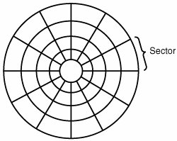
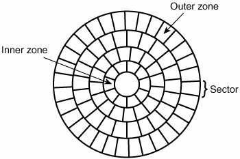
Low-Level FormattingDuring a low-level format, the formatting program divides the disk's tracks into a specific number of sectors, creating the intersector and intertrack gaps and recording the sector header and trailer information. The program also fills each sector's data area with a dummy byte value or a pattern of test values. For floppy disks, the number of sectors recorded on each track depends on the type of disk and drive. For hard disks, the number of sectors per track depends on the drive and the controller interface. Originally, PC hard disk drives used a separate controller that took the form of an expansion card or was integrated into the motherboard. Because the controller could be used with various disk drives and might even have been made by a different manufacturer, some uniformity had to exist in the communications between the controller and the drive. For this reason, the number of sectors written to a track tended to be relatively consistent. The original ST-506/412 MFM controllers always placed 17 sectors per track on a disk, although ST-506/412 controllers with RLL encoding increased the number of sectors to 25 or 26 per track; ESDI drives had 32 or more sectors per track. The ATA/IDE and SCSI drives found in PCs today can have anywhere from 17 to 900 or more sectors per track. Virtually all ATA and SCSI drives use a technique called zoned-bit recording (ZBR), sometimes shortened to zoned recording, which writes a variable number of sectors per track. Without zoned recording, the number of sectors, and therefore bits, on each track is a constant. This means the actual number of bits per inch will vary. More bits per inch will exist on the inner tracks, and fewer will exist on the outer. The data rate and rotational speed will remain constant, as will the number of bits per track. Figure 9.4 shows a drive recorded with the same number of sectors per track. Figure 9.4. Standard recording, where the same number of sectors comprise every track. A standard recording wastes capacity on the outer tracks because it is longer and yet holds the same amount of data (more loosely spaced) as the inner tracks. One way to increase the capacity of a hard drive during the low-level format is to create more sectors on the disks' outer cylinders than on the inner ones. Because they have a larger circumference, the outer cylinders can hold more data. Drives without zoned recording store the same amount of data on every cylinder, even though the tracks of the outer cylinders might be twice as long as those of the inner cylinders. The result is wasted storage capacity because the disk medium must be capable of storing data reliably at the same density as on the inner cylinders. When the number of sectors per track is fixed, as in older controllers, the drive capacity is limited by the density of the innermost (shortest) track. Drives that use zoned recording split the cylinders into groups called zones, with each successive zone having more sectors per track as you move outward from the center of the disk. All the cylinders in a particular zone have the same number of sectors per track. The number of zones varies with specific drives, but most drives have 10 or more zones. Figure 9.5 shows a drive with zoned-bit recording. Figure 9.5. Zoned recording, where the number of sectors per track increases within each zone, moving out from the center. Another effect of zoned recording is that transfer speeds vary depending on which zone the heads are in. A drive with zoned recording still spins at a constant speed. Because more sectors exist per track in the outer zones, however, data transfer is fastest there. Consequently, data transfer is slowest when reading or writing to the inner zones. That is why virtually all drives today report minimum and maximum sustained transfer rates, which depend on where on the drive you are reading from or writing to. As an example, see Table 9.3, which shows the zones defined for a Hitachi Travelstar 7K60 2 1/2" notebook drive, the sectors per track for each zone, and the resulting data transfer rate. This is one of the fastest laptop hard drives on the market.
This drive has a total of 54,288 cylinders, which are divided into 16 zones averaging 3,393 cylinders each. Zone 0 consists of the outermost cylinders, which are the longest and contain the most sectors: 720 for each track. Because each sector is 512 bytes, each track in the outer zone contains 368,640 bytes of data. The inner zone has only 360 sectors per track, which means each track in the inner zone holds 184,320 bytes. With zoned recording, this drive averages 545.63 sectors per track. Without zoned recording, the number of sectors per track would be limited to 360 for all tracks. The use of zoned recording therefore provides nearly a 52% increase in the storage capacity of this particular drive. Also notice the difference in the data transfer rates for each of the zones. Because the drive spins at 7,200 rpm, it completes a single revolution every 1/120 of a second, or every 8.33 milliseconds. Therefore, the data transfer speed varies depending on which zone you are reading and writing. In the outer zone, the data transfer rate is 44.24MBps, whereas in the inner zone it is only 22.12MBps. The average transfer rate for this drive is 33.52MBps. This is one reason you might notice huge discrepancies in the results produced by disk drive benchmark programs. A test that reads or writes files on the outer tracks of the disk naturally yields far better results than one conducted on the inner tracks. It might appear as though your drive is running more slowly when the problem is actually that the test results you are comparing stem from disk activity on different zones. Another thing to note is that this drive conforms to the ATA-6 specification and is capable of running in Ultra-ATA/100 mode (also called UDMA-100), which implies a transfer speed of 100MBps. As you can see, that is entirely theoretical because the true media transfer speed of this drive varies between about 22MBps and 44MBps, averaging about 33MBps overall. The interface transfer rate is just that: what the interface is capable of. It has little bearing on the actual capabilities of the drive. Drives with separate controllers used in the past could not handle zoned recording because no standard way existed to communicate information about the zones from the drive to the controller. With SCSI and ATA disks, however, formatting individual tracks with different numbers of sectors became possible because these drives have the disk controller built in. The built-in controllers on these drives are fully aware of the zoning algorithm and can translate the physical cylinder, head, and sector numbers to logical cylinder, head, and sector numbers so the drive appears to have the same number of sectors on each track. Because the PC BIOS is designed to handle only a single number of sectors per track throughout the entire drive, a zoned drive must run by using a sector translation scheme. The use of zoned recording enables drive manufacturers to increase the capacity of their hard drives by 20%50% or more when compared with a fixedsector-per-track arrangement. All modern drives use zoned recording. PartitioningCreating a partition on a hard disk drive enables it to support separate file systems, each in its own partition. Each file system can then use its own method to allocate file space in logical units called clusters or allocation units. Every hard disk drive must have at least one partition on it and can have up to four partitions, each of which can support the same or different type file systems. Three common file systems are used by PC operating systems today:
Up until the release of XP, FAT32 was by far the most popular file system. Because NTFS is native to XP, NTFS is now more popular in newer systems. Still, the FAT file system is accessible by nearly every operating system, which makes it the most compatible in a mixed OS environment. FAT32 and NTFS provide additional features but are not universally accessible by other operating systems. Partitioning normally is accomplished by running the disk partitioning program that comes with your operating system. The name and exact operation of the disk partitioning program varies with the operating system. For example, FDISK is used by DOS and Windows 9x/Me for this task, whereas the DISKPART command or the Disk Management snap-in component of the Computer Management service are used with Windows XP. FDISK, DISKPART, and other disk partitioning tools enable you to select the amount of space on the drive to use for a partition, from a single megabyte (or 1%) of the drive up to the entire capacity of the drive or as much as the particular file system will allow. You usually should have as few partitions as possible, and many people (myself included) try to stick with only one or two at the most. This was more difficult before FAT32 because the maximum partition size for a FAT16 partition was only 2GB. With FAT32, though, the maximum partition size can be up to 2048GB. Caution FDISK, DISKPART, Disk Management, and other disk partitioning tools included in operating systems can't be used to change the size of a partition; all they can do is remove or create partitions. The act of removing or creating a partition destroys and loses access to data that was contained in the partition or that was on that part of the disk. To manipulate partitions without destroying data, you can use third-party utility programs, such as Partition Magic from Symantec or Partition Commander from V-Communications. After a drive is partitioned, each partition must then be high-level formatted by the operating system that will use it. High-Level FormattingDuring the high-level format, the operating system writes the structures necessary for managing files and data on the disk. For example, FAT partitions have a Volume Boot Sector (VBS), two copies of a file allocation table (FAT), and a root directory on each formatted logical drive. These data structures enable the operating system to manage the space on the disk, keep track of files, and even manage defective areas so they do not cause problems. High-level formatting is not really a physical formatting of the drive, but rather the creation of a table of contents for the disk. In low-level formatting, which is the real physical formatting process, tracks and sectors are written on the disk. As mentioned, the DOS and Windows 9x/Me FORMAT command can perform both low-level and high-level format operations on a floppy disk, but it performs only the high-level format for a hard disk. Low-level formats of ATA and SCSI hard disk drives are performed by the manufacturer and should almost never be performed by the end user. The only time I low-level format ATA or SCSI drives is when I am attempting to repair a format that has become damaged (parts of the disk become unreadable) or in some cases when I want to wipe away all data on the drive. | |||||||||||||||||||||||||||||||||||||||||||||||||||||||||||||||||||||||||||||||||||||||||||||||||||||||||||||||||||||||||||||||||||||||||
EAN: 2147483647
Pages: 283