Floppy Disk Drives, Past and Present
| Alan Shugart is generally credited with inventing the floppy disk drive in 1967 while working for IBM. One of Shugart's senior engineers, David Noble, actually proposed the flexible medium (then 8" in diameter) and the protective jacket with the fabric lining. Shugart left IBM in 1969, and in 1976 his company, Shugart Associates, introduced the minifloppy (5 1/4") disk drive. It, of course, became the standard eventually used by personal computers, rapidly replacing the 8" drives. He also helped create the Shugart Associates System Interface (SASI), which was later renamed small computer system interface (SCSI) when approved as an ANSI standard. Sony introduced the first 3 1/2" microfloppy drives and disks in 1981. The first significant company to adopt the 3 1/2" floppy for general use was Hewlett-Packard in 1984 with its partially PC-compatible HP-150 system. The adoption of the 3 1/2" drive in the PC was solidified when IBM started using the drive in 1986 in some systems and finally switched its entire PC product line to 3 1/2" drives in 1987. Note that all PC floppy disk drives are still based on (and mostly compatible with) the original Shugart designs, including the electrical and command interfaces. Compared to other parts of the PC, the floppy disk drive has undergone relatively few changes over the years. The following sections discuss standard 3 1/2" 1.44MB floppy disk drives and media, how they function, and how to properly install and service them. Older types of floppy disk drives, including 3 1/2" 720KB, 3 1/2" 2.88MB, 5 1/4" 1.2MB, and 5 1/4" floppy drives, are no longer in common use. If you need more information about these drives, see the Technical Reference section of the DVD included with this book. Table 10.2 provides a brief comparison of these drives to each other. As you can see, the different disk capacities are determined by several parameters, some of which seem to remain constant on all drives. Others, however, change from drive to drive. For example, all drives use 512-byte physical sectors, which is true for hard disks as well.
Alternatives to Floppy DrivesIn 2002, many companies started selling systems without floppy drives. This started with notebook computers, where internal floppy drives were first eliminated and replaced with external (normally USB) drives. Most newer notebooks no longer include a floppy drive with the system, offering only external USB models as an option. Starting in 2003, many desktop system manufacturers likewise stopped including floppy drives in their standard system configurations. An optional USB floppy drive can be used as a bootable drive if the BIOS permits it, as is the case with many recent systems. Several alternatives to floppy storage are available, although both Zip and LS-120/LS-240 (SuperDisk) drives have failed in the marketplace as floppy drive replacements in new PCs. The Mt. Rainier (EasyWrite) standard, which was introduced in 2002, allows CD-RW and DVD+-RW drives to serve as replacements for the floppy. Prior to Mt. Rainier, the CD/DVD drives lacked defect management, as well as native OS support.
Many people are also now using USB flash memory devices, often called thumb drives or keychain drives, to transport small to medium amounts of data (up to 2GB or more) between systems. However, floppy drives remain useful for data recovery or computer forensics, where data retrieval from older media is often necessary. Even though I don't use floppy drives much for storing new information, I maintain systems with both 5 1/4" and 3 1/2" drives so I can read data from older media in a forensics or data-recovery situation. 1.44MB 3 1/2" DrivesThe 3 1/2", 1.44MB, high-density (HD) drives first appeared from IBM in the PS/2 product line introduced in 1987. Most other computer vendors started offering the drives as an option in their systems immediately afterward. For systems that include floppy drives, the 1.44MB type is still by far the most popular. The drive records 80 cylinders consisting of 2 tracks each with 18 sectors per track, resulting in a formatted capacity of 1.44MB. Some disk manufacturers label these disks as 2.0MB, and the difference between this unformatted capacity and the formatted usable result is lost during the format. Note that the 1440KB of total formatted capacity does not account for the areas the FAT file system reserves for file management, leaving only 1423.5KB of actual file-storage area. The drive spins at 300rpm and in fact must spin at that speed to operate properly with existing high-and low-density controllers. To use the 500KHz data rate (the maximum from most standard high-and low-density floppy controllers), these drives must spin at a maximum of 300rpm. If the drives were to spin at the faster 360rpm rate of the 5 1/4" drives, they would have to reduce the total number of sectors per track to 15; otherwise, the controller could not keep up. In short, the 1.44MB 3 1/2" drives store 1.2 times the data of the 5 1/4" 1.2MB drives, and the 1.2MB drives spin exactly 1.2 times faster than the 1.44MB drives. The data rates used by both of these HD drives are identical and compatible with the same controllers. In fact, because these 3 1/2" HD drives can run at the 500KHz data rate, a controller that can support a 1.2MB 5 1/4" drive can also support the 1.44MB drives. Other types of floppy drives that have been used in the past include the following:
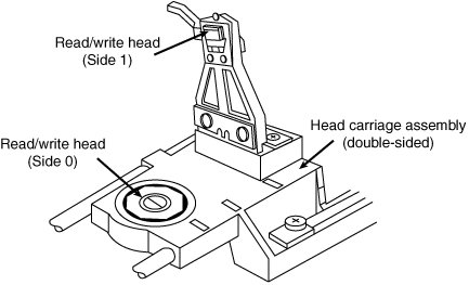
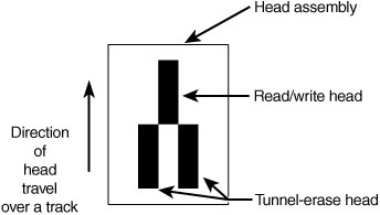
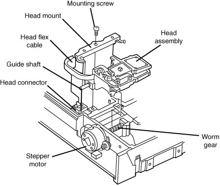
Floppy Drive InterfacesFloppy drives are interfaced to the PC in several ways. Many still include the traditional floppy controller interface (even if a drive is not installed in the system), but some now use the USB interface; this is covered later in this chapter. Because the traditional floppy controller only works internally, all external drives are interfaced via USB or some other alternative interface. USB drives often have a standard floppy drive inside an external box with a USB-to-floppy controller interface converter inside. Newer, legacy-free systems don't include a traditional floppy controller and typically use USB as the floppy interface. In the past, some drives have been available in FireWire (IEEE 1394) or even parallel interfaces as well. For more information on USB or the parallel port, see Chapter 15. Drive ComponentsAll floppy disk drives, regardless of type, consist of several basic common components. To properly install and service a disk drive, you must be able to identify these components and understand their functions (see Figure 10.2). Figure 10.2. A typical 3 1/2" floppy disk drive.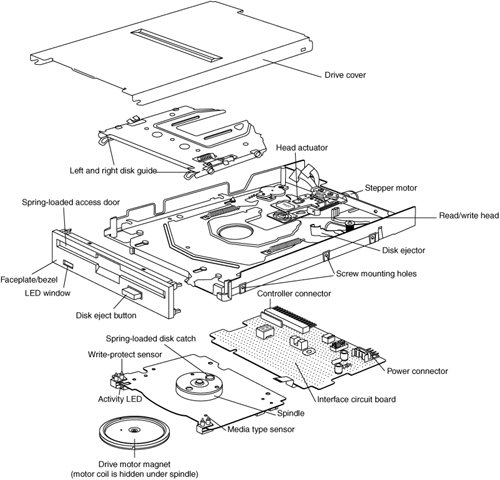 Read/Write HeadsA floppy disk drive usually has two read/write headsone for each side of the disk, with both heads being used for reading and writing on their respective disk sides (see Figure 10.3). At one time, single-sided drives were available for PC systems (the original PC had such drives), but today single-sided drives are a faded memory. Figure 10.3. A double-sided drive head assembly. Note Many people do not realize that Head 0, or the first head on a floppy disk drive, is the bottom one. Single-sided drives, in fact, used only the bottom head; the top head has been replaced by a felt pressure pad. Another bit of disk trivia is that the top head (Head 1) is not positioned directly over the bottom head (Head 0). The top head is instead offset by either four or eight tracks inward from the bottom head, depending on the drive type. A motor called a head actuator moves the head mechanism. The heads can move in and out over the surface of the disk in a straight line to position themselves over various tracks. On a floppy drive, the heads move in and out tangentially to the tracks they record on the disk. This is different from hard disks, where the heads move on a rotating arm similar to the tone-arm of a record player. Because the top and bottom heads are mounted on the same rack, or mechanism, they move in unison and can't move independently of each other. The upper and lower heads each defines tracks on its respective side of the disk medium, whereas at any given head position, the tracks under the top and bottom head simultaneously are called a cylinder. Most floppy disks are recorded with 80 tracks on each side (160 tracks total), which is 80 cylinders. The heads themselves are made of soft ferrous (iron) compounds with electromagnetic coils. Each head is a composite design, with a read/write head centered within two tunnel-erase heads in the same physical assembly (see Figure 10.4). Figure 10.4. Composite construction of a typical floppy disk drive head. Floppy disk drives use a recording method called tunnel erasure. As the drive writes to a track, the trailing tunnel-erase heads erase the outer bands of the track, trimming it cleanly on the disk. The heads force the data into a specified narrow "tunnel" on each track. This process prevents the signal from one track from being confused with the signals from adjacent tracks, which would happen if the signal were allowed to naturally "taper off" to each side. Alignment is the placement of the heads with respect to the tracks they must read and write. Head alignment can be checked only against some sort of reference-standard disk recorded by a perfectly aligned machine. These types of disks are available, and you can use one to check your drive's alignment. However, this is usually not practical for the end user because one calibrated analog alignment disk can cost more than a new drive. The floppy disk drive's two heads are spring-loaded and physically grip the disk with a small amount of pressure, which means they are in direct contact with the disk surface while reading from and writing to the disk. Because most floppy disk drives spin at only 300rpm or 360rpm (Sony drives spin at 600rpm), this pressure does not present an excessive friction problem. Some newer disks are specially coated with Teflon or other compounds to further reduce friction and enable the disk to slide more easily under the heads. Because of the contact between the heads and disk, a buildup of the magnetic material from the disk eventually forms on the heads. The buildup should periodically be cleaned off the heads as part of a preventive maintenance or normal service program. Most manufacturers recommend cleaning the heads after every 40 hours of drive operation, whichconsidering how often people use these drives todaycould be a lifetime. To read and write to the disk properly, the heads must be in direct contact with the magnetic medium. Very small particles of loose oxide, dust, dirt, smoke, fingerprints, or hair can cause problems with reading and writing the disk. Disk and drive manufacturers' tests have found that a spacing as little as .000032" (32 millionths of an inch) between the heads and medium can cause read/write errors. You now can understand why it is important to handle disks carefully and avoid touching or contaminating the surface of the disk medium in any way. The rigid jacket and protective shutter for the head access aperture on 3 1/2" disks is excellent for preventing problems caused by contamination. Disks that are 5 1/4" do not have the same protective elements, which is perhaps one reason they initially began to fall into disuse. If you still use 5 1/4" floppy disks, you should exercise extra care in their handling. I recommend copying any archival data over to recordable CD or DVD media if your situation doesn't require keeping the data on the original media. The Head ActuatorThe head actuator for a floppy disk drive is what moves the heads across the disk and is driven by a special kind of motor, called a stepper motor (see Figure 10.5). This type of motor does not spin around continuously; rather, the motor turns a precise specified distance and stops. Stepper motors are not infinitely variable in their positioning; they move in fixed incrementsor detentsand must stop at a particular detent position. This is ideal for disk drives because the location of each track on the disk can then be defined by moving one or more increments of the motor's motion. The disk controller can instruct the motor to position itself any number of steps within the range of its travel. To position the heads at cylinder 25, for example, the controller instructs the motor to go to the 25th detent position or step from Cylinder 0. Figure 10.5. An expanded view of a stepper motor and head actuator. The stepper motor can be linked to the head rack in one of two ways. In the first, the link is a coiled, split-steel band. The band winds and unwinds around the spindle of the stepper motor, translating the rotary motion into linear motion. Most 3 1/2" drives use the more compact worm-gear arrangement rather than a band. In this type of drive, the head assembly rests on a worm gear driven directly off the stepper motor shaft. Most stepper motors used in floppy disk drives can step in specific increments that relate to the track spacing on the disk. The ancient 5 1/4" 360KB drives are the only 48 TPI drives that use the 3.6° increment stepper motor; all other drive types typically use the 1.8° stepper motor. On most drives, the stepper motor is a small, cylindrical object near one corner of the drive. A stepper motor usually has a full travel time of about one fifth of a secondabout 200ms. On average, a one-half stroke is 100ms, and a one-third stroke is 66ms. The timing of a one-half or one-third stroke of the head-actuator mechanism is often used to determine the reported average access time for a disk drive. Average access time is the normal amount of time the heads spend moving at random from one track to another. Floppy Drive Spindle MotorThe spindle motor is what spins the disk. The normal speed of rotation is either 300rpm or 360rpm, depending on the type of drive. The 5 1/4" high-density (HD) drive is the only drive that spins at 360rpm. All others, including the 5 1/4" double-density (DD), 3 1/2" DD, 3 1/2" HD, and 3 1/2" extra-high density (ED) drives, spin at 300rpm. This is a slow speed when compared to a hard disk drive, which helps explain why floppy disk drives have much lower data transfer rates. However, this slow speed also enables the drive heads to be in physical contact with the disk while it is spinning, without causing friction damage. The spindle motor in early drives used a belt-driven mechanism to spin the disk, but all modern drives use a direct-drive system with no belts. The direct-drive systems are more reliable and less expensive to manufacture, as well as smaller in size. The earlier belt-driven systems did have more rotational torque available to turn a sticky disk because of the torque multiplication factor of the belt system. Most newer direct-drive systems, on the other hand, use an automatic torque-compensation capability that sets the disk-rotation speed to a fixed 300rpm or 360rpm and compensates with additional torque for highfriction disks or less torque for more slippery ones. Besides compensating for varying amounts of friction, this arrangement eliminates the need to adjust the rotational speed of the drivesomething that was frequently required on older drives. Floppy Drive Circuit BoardsA disk drive always incorporates one or more logic boards, which are circuit boards that contain the circuitry used to control the head actuator, read/write heads, spindle motor, disk sensors, and other components on the drive. The logic board implements the drive's interface to the controller board in the system unit. The standard interface that all PC floppy disk drives use is called the Shugart Associates SA400 interface. It was invented in the 1970s and is based on the NEC 765 controller chip. All modern floppy controllers contain circuits that are compatible with the original NEC 765 chip. This industry-standard interface is why you can purchase drives from almost any manufacturer and they will all be compatible. The Floppy ControllerAt one time, the controller for a computer's floppy disk drives took the form of a dedicated expansion card installed in an Industry Standard Architecture (ISA) bus slot. Later implementations used a multifunction card that provided the IDE/ATA, parallel, and serial port interfaces in addition to the floppy disk drive controller. Today's PCs have the floppy controller integrated into the motherboard. Some systems use a Super I/O chip that also includes the serial and parallel interfaces, among other things; other systems might use a South Bridge chip that contains the Super I/O functions. Regardless of the location of the floppy controller logic, it is still interfaced to the system via the ISA or LPC (low pin count) bus and functions exactly as if it were a card installed in an ISA slot. These built-in controllers are typically configured via the system BIOS Setup routines and can be disabled if an actual floppy controller card is going to be installed. Whether it is built in or not, each primary floppy controller uses a standard set of system resources:
These system resources are standardized and generally not changeable. This usually does not present a problem because no other devices will try to use these resources (which would result in a conflict). Systems advertised as "legacy-free" don't include a Super I/O chip and therefore don't have a built-in floppy controller. Such systems can still use a floppy drive, but only in the form of an external USB drive. Unlike the ATA interface used primarily by hard disks and optical drives, the floppy disk controller has not changed much over the years. Virtually the only thing that has changed is the controller's maximum speed. As the data density of floppy disks (and their capacity) has increased over the years, the controller speed has had to increase, as well. Nearly all floppy disk controllers in computers today support speeds of up to 1 megabit per second (Mbps), which supports all the standard floppy disk drives. 500 kilobits per second (Kbps) controllers can support all floppy disk drives except the 2.88MB extra high-density models. Very old computers used 250Kbps controllers that could support only 360KB 5 1/4" and 720KB 3 1/2" drives. Tip The best way to determine the speed of the floppy disk drive controller in your computer is to examine the floppy disk drive options provided by the system BIOS.
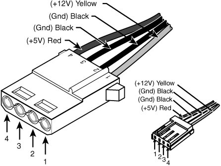
Although traditional floppy controller cards and multi I/O cards have provisions for two floppy drivesA: and B:many recent systems that integrate Super I/O features into the South Bridge chip on the motherboard support only a single floppy drive. The FaceplateThe faceplate, or bezel, is the plastic piece that comprises the front of the drive. This piece, usually removable, comes in various colors and configurations. Most floppy drive manufacturers offer drives with matching faceplates in gray, beige, or black and with a choice of red, green, or yellow activity LEDs in their retail-packaged drives. This enables a system builder to better match the drive to the aesthetics of the case for a seamless, integrated, and more professional look. Tip OEM "bare" floppy drives might not include faceplate or LED options. Some OEM drives don't even include a faceplate at all because they were manufactured for systems that use a custom-made front panel that incorporates a protective door and pushbutton for ejecting disks from the drive. Power and Data ConnectorsExternal USB floppy drives use the USB connector for power and data. However, nearly all internal floppy disk drives have two connectorsone for power to run the drive and the other to carry the control and data signals to and from the drive. These connectors are fairly standardized in the computer industry. A 4-pin inline connector (called Mate-N-Lock by AMP) in both large (Molex) and small (Berg) styles is used for power (see Figure 10.6), and a 34-pin connector in both edge and pin header designs is used for the data and control signals. Typically, 5 1/4" drives use the large-style power connector (the same as used by ATA/IDE hard disks and CD/DVD drives) and the 34-pin edge-type connector, whereas most 3 1/2" drives use the smaller version of the power connector and the 34-pin header-type logic connector. The drive controller and logic connectors and pinouts are detailed later in this chapter, as well as on the Vendor List on this book's DVD. Figure 10.6. Large (Molex) connector for 5 1/4" drives and small (Berg) connector for 3 1/2" drives female power supply cable connectors. Both the Molex and Berg power connectors from the power supply are female plugs. They plug in to the male portion, which is attached to the drive itself. Note that the pin-to-signal designations on the small connector are the opposite of those on the large connector. One common problem with installing 3 1/2" drives in some systems is that the power supply might not have an available small-style (Berg) power connector used by the smaller drives. An adapter cable that converts the Molex peripheral power connector to the proper Berg connector used on most 3 1/2" drives is available from Dalco (www.dalco.com) under p/n 47425 and from other sources. You can also use a splitter that converts a Molex connector into one each Berg and Molex (Dalco p/n 43435) or into two Berg connectors (Dalco p/n 51075). Splitters are also available from other sources. The Floppy Disk Controller CableThe 34-pin connector on an internal floppy disk drive takes the form of either an edge connector (on 5 1/4" drives) or a pin connector (on 3 1/2" drives). The pinouts for the floppy controller connector are shown in Table 10.3.
The cable used to connect the floppy disk drive(s) to the controller on the motherboard is sometimes quite strange. To support various drive configurations, the cable might have up to five connectors on ittwo edge connectors and two pin connectors to attach to the drives and one pin connector to connect to the controller. The cable has redundant connectors for each of the two drives (A and B) supported by the standard floppy disk drive controller, so you can install any combination of 5 1/4" and 3 1/2" drives (see Figure 10.7). Figure 10.7. Standard five-connector floppy interface cable.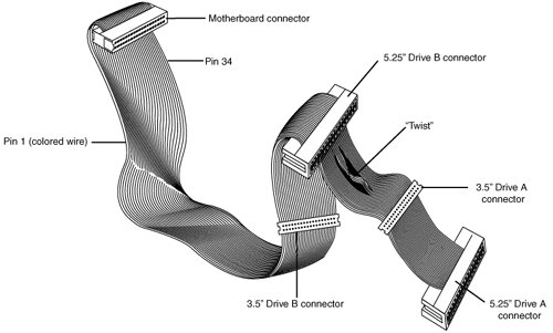 You can also purchase floppy drive cables made for only 3 1/2" drives. These omit the edge connectors shown in Figure 10.7. In addition to the connectors, the cable has a special twist that inverts the signals of wires 1016. These are the wires carrying the Drive Select (DS) and Motor Enable signals for each of the two drives. Very old floppy disk drives have DS jumpers designed to enable you to select whether a given drive should be recognized as A or B (really old ones allow a third and fourth setting as well). You might not even know that these jumpers exist because the twist in the cable prevents you from having to adjust them, and as such they have been eliminated from most newer drives. When installing two floppy disk drives in one system (admittedly a rarity nowadays), the cable electrically changes the DS configuration of the drive that is plugged in after the twist. Thus, the twist causes a drive physically set to the second DS position (B) to appear to the controller to be set to the first DS position (A). The adoption of this cable has enabled the use of a standard jumper configuration for all floppy disk drives, regardless of whether you install one or two drives in a computer. If you install only a single floppy disk drive, you use the connector after the twist, which causes the drive to be recognized as drive A. Although it's seldom necessary today, many computer BIOS setup programs have an option enabling you to swap drives A: and B: without adjusting drive cables. If you have a computer with the old 5 1/4" floppy as B: for use with old software and need to use it as A:, you can use this BIOS option, if present, to change the drive setup without opening your system. Note The original Shugart SA400 floppy interface made for 5 1/4" floppy drives supported up to four drives on a single cable. However, IBM modified the controller pinout to support only two drives and eliminate the need to change drive select jumpers on the drive. To learn more about these changes, see "Secrets of the Cable Twist" in Chapter 11 of Upgrading and Repairing PCs, 16th Edition, included on the DVD packaged with this book. How the Operating System Uses a Floppy DiskThe physical operation of a 3 1/2" disk drive is fairly simple to describe. The disk rotates in the drive at 300rpm. With the disk spinning, the heads can move in and out approximately one inch and write 80 tracks. The tracks are written on both sides of the disk and are therefore sometimes called cylinders. A single cylinder comprises the tracks on the top and bottom of the disk. The heads record by using a tunnel-erase procedure that writes a track to a specified width and then erases the edges of the track to prevent interference with any adjacent tracks. To the operating system, data on your PC disks is organized in tracks and sectors, just as on a hard disk drive. Tracks are narrow, concentric circles on a disk; sectors are pie-shaped slices of the individual tracks. A 3 1/2" 1.44MB floppy disk drive has the following specifications:
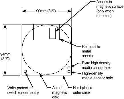
For the specifications for obsolete disk drive types, see the Technical Reference section of the DVD packaged with this book. The floppy disk's capacity can actually be expressed in various ways. For example, what we call a 1.44MB disk really stores 1.475MB if you go by the correct decimal prefix definition for a megabyte. The discrepancy comes from the fact that in the past floppies were designated by their kilobinary (1,024-byte) capacities, which were originally (and improperly) abbreviated as KB. To prevent ambiguities in binary versus decimal number interpretations, the International Electrotechnical Commission (IEC) has designated KiB as the correct abbreviation for kilobinary. Despite the IEC standards, the traditional method when discussing floppy drives or disks is to refer to the capacity of a floppy by the number of kilobinary bytes (1,024 bytes equals 1KiB) but to use the otherwise improper abbreviation KB instead. This has also been improperly extended to the abbreviation MB. Therefore, a floppy disk with an actual capacity of 1,440KiB is instead denoted as a 1.44MB disk, even though it would really be 1.406MiB (megabinary bytes) or 1.475MB (million bytes) if we went by the correct definitions for MiB (mebibyte) and MB (megabyte). For the remainder of this chapter, I will refer to the capacity of the various floppy disks according to the previously used conventions rather than the more technically accurate IEC-designated binary and decimal prefixes. Note As with hard disk drives, using the same prefixes for both decimal and binary multiples has resulted in a great deal of confusion. The IEC prefixes for binary multiples was designed to eliminate this confusion. For more information on prefixes for binary multiples, see http://physics.nist.gov/cuu/Units/binary.html. Also, refer to the section "Capacity Measurements" in Chapter 9, "Hard Disk Storage." Like blank sheets of paper, new, unformatted disks contain no information. Formatting a disk is similar to adding lines to the paper so you can write straight across. Formatting the disk writes the information the operating system needs to maintain a directory and file table of contents. A full format rewrites the file system structures, removing any existing data in the process. This is the equivalent of both a high-level and low-level format on a hard disk. However, unlike a hard disk, a floppy disk does not need to be partitioned. Note The Quick Format option available in most versions of Windows, including Windows XP, erases the contents of the disk and verifies the file system rather than rewriting the file system. If you run FORMAT.EXE from the command line, the /Q option also performs a quick format. Unfortunately, Quick Format is not very good at determining whether you have problems with your floppy disk's file system. If you need to ensure that the floppy disk is properly formatted (such as in the case of a used disk you want to use for another task), you should not use the Quick Format option. Windows NT, 2000, and XP perform a full (low-level) format that rewrites the file system and clears the disk if Quick Format is not selected. Windows 9x/Me offers Quick (erase), which is the same as selecting Quick Format, Full, Copy System Files Only in Windows XP. Select Full to rewrite the file system and clear the disk of existing data. When you format a floppy disk, the operating system reserves the track nearest to the outside edge of a disk (track 0) almost entirely for its purposes. Track 0, Side 0, Sector 1 contains the Volume Boot Record (VBR), or Boot Sector, that the system needs to begin operation. The next few sectors contain the file allocation tables (FATs), which keep records of which clusters or allocation units on the disk contain file information and which are empty. Finally, the next few sectors contain the root directory, in which the operating system stores information about the names and starting locations of the files on the disk. Note that floppy disks have been sold in preformatted form for a few years now. This saves time because the formatting can take a minute or more per disk. Even if disks come preformatted, they can always be reformatted later. This is useful if you accidentally purchased MAC-formatted disks for your PC; a PC can't use a MAC-formatted disk unless you reformat it. CylindersWhen discussing the location of data on a floppy disk, the cylinder number is normally used in place of the track number because all floppy drives today are double-sided. A cylinder on a floppy disk includes two tracks: the one on the bottom of the disk above Head 0 and the one on the top of the disk below Head 1. Because a disk can't have more than two sides and the drive has two heads, there are always two tracks per cylinder for floppy disks. Hard disk drives, on the other hand, can have multiple disk platterseach with two headsresulting in many tracks per single cylinder. The simple rule is that there are as many tracks per cylinder as there are heads on the drive. Cylinders were discussed in more detail in Chapter 9. Clusters or Allocation UnitsA cluster also is called an allocation unit. The term is appropriate because a single cluster is the smallest unit of the disk that the operating system can allocate when it writes a file. A cluster or an allocation unit consists of one or more sectorsusually a power of two (1, 2, 4, 8, and so on). Having more than one sector per cluster reduces the FAT size and enables the OS to run more quickly because it has fewer individual clusters to manage. The tradeoff is in some wasted disk space. Because the OS can manage space only in the cluster size unit, every file consumes space on the disk in increments of one cluster. However, 3 1/2" 1.44MB floppy drives store so little information that the default cluster (allocation unit) size is one sector (512 bytes). Disk ChangeThe standard PC floppy controller and drive use a special signal on pin 34 called Disk Change to determine whether the disk has been changedor more accurately, to determine whether the same disk loaded during the previous disk access is still in the drive. Disk Change is a pulsed signal that changes a status register in the controller to let the system know that a disk has been either inserted or ejected. This register is set to indicate that a disk has been inserted or removed (changed) by default. The register is cleared when the controller sends a step pulse to the drive and the drive responds, acknowledging that the heads have moved. At this point, the system knows that a specific disk is in the drive. If the Disk Change signal is not received before the next access, the system can assume that the same disk is still in the drive. Any information read into memory during the previous access can therefore be reused without rereading the disk. Because of this process, systems can buffer or cache the contents of the FAT or directory structure of a disk in the system's memory. By eliminating unnecessary rereads of these areas of the disk, the apparent speed of the drive is increased. If you move the door lever or eject button on a drive that supports the Disk Change signal, the DC pulse is sent to the controller, thus resetting the register and indicating that the disk has been changed. This procedure causes the system to purge buffered or cached data that had been read from the disk because the system can't be sure that the same disk is still in the drive. One interesting problem can occur when certain drives are installed in a 16-bit or greater system. As mentioned, some drives use pin 34 for a "Ready" (RDY) signal. The RDY signal is sent whenever a disk is installed and rotating in the drive. If you install a drive that has pin 34 set to send RDY, the system thinks it is continuously receiving a Disk Change signal, which causes problems. Usually, the drive fails with a Drive Not Ready error and is inoperable. The only reason the RDY signal exists on some drives is that it happens to be a part of the standard Shugart SA400 disk interface; however, it has never been used in PC systems. The biggest problem occurs if the drive should be sending the DC signal on pin 34 but isn't. If a system is told (through CMOS setup) that the drive is any type other than a 360KB (which can't ever send the DC signal), the system expects the drive to send DC whenever a disk has been ejected. If the drive is not configured properly to send the signal, the system never recognizes that a disk has been changed. Therefore, even if you do change the disk, the system still acts as though the first disk is in the drive and holds the first disk's directory and FAT information in RAM. This can be dangerous because the FAT and directory information from the first disk can be partially written to any subsequent disks written to in the drive. Caution If you have ever seen a system with a floppy disk drive that shows "phantom directories" of the previously installed disk, even after you have changed or removed it, you have experienced this problem firsthand. The negative side effect is that all disks after the first one you place in this system are in extreme danger. You likely will overwrite the directories and FATs of many disks with information from the first disk. If it's even possible at all, data recovery from such a catastrophe can require quite a bit of work with utility programs, such as Norton Utilities (part of the Norton SystemWorks suite). These problems with Disk Change most often are traced to an incorrectly configured drive. A damaged floppy cable can also cause Disk Change to fail. Windows Explorer doesn't always display the new contents of a drive. Press the F5 key to refresh the display after you change floppy disks to force the computer to read the new disk. If the drive you are installing is a 5 1/4" 1.2MB or 3 1/2" 720KB, 1.44MB, or 2.88MB drive, be sure to set pin 34 to send the Disk Change (DC) signal. Most drives come permanently preset this way, but some older drives have used a jumper (usually labeled DC) to set this option. Analyzing 3 1/2" Floppy Disk Media Construction3 1/2" disks differ from the older 5 1/4" disks in both construction and physical properties. The flexible (or floppy) disk is contained within a plastic jacket. The 3 1/2" disks are covered by a more rigid jacket than are the 5 1/4" disks. The disks within the jackets, however, are virtually identical except, of course, for size. The 3 1/2" disks use a much more rigid plastic case than 5 1/4" disks, which helps stabilize the magnetic medium inside. Therefore, the disks can store data at track and data densities greater than the 5 1/4" disks (see Figure 10.8). A metal shutter protects the media-access hole. The drive manipulates the shutter, leaving it closed whenever the disk is not in a drive. The medium is then completely insulated from the environment and from your fingers. The shutter also obviates the need for a disk jacket. Figure 10.8. Construction of a 3 1/2" floppy disk. Because the shutter is not necessary for the disk to work, you can remove it from the plastic case if it becomes bent or damaged. Pry it off the disk case; it will pop off with a snap. You also should remove the spring that pushes it closed. Additionally, after removing the damaged shutter, you should copy the data from the damaged disk to a new one. Rather than an index hole in the disk, the 3 1/2" disks use a metal center hub with an alignment hole. The drive "grasps" the metal hub, and the hole in the hub enables the drive to position the disk properly. On the lower-left part of the disk is a hole with a plastic sliderthe write-protect/enable hole. When the slider is positioned so the hole is visible, the disk is write-protected, meaning the drive is prevented from recording on the disk. When the slider is positioned to cover the hole, writing is enabled, and you can save data to the disk. For more permanent write-protection, some commercial software programs are supplied on disks with the slider removed so you can't easily enable recording on the disk. This is exactly opposite of a 5 1/4" floppy, in which covered means write-protected, not write-enabled. On the other (right) side of the disk from the write-protect hole is usually another hole called the media-density-selector hole. If this hole is present, the disk is constructed of a special medium and is therefore an HD or ED disk. If the media-sensor hole is exactly opposite the write-protect hole, it indicates a 1.44MB HD disk. If the media-sensor hole is located more toward the top of the disk (the metal shutter is at the top of the disk), it indicates a 2.88MB ED disk. No hole on the right side means that the disk is a low-density disk. Most 3 1/2" drives have a media sensor that controls recording capability based on the absence or presence of these holes. The actual magnetic medium in both the 3 1/2" and 5 1/4" disks is constructed of the same basic materials. They use a plastic base (usually Mylar) coated with a magnetic compound. High-density disks use a cobalt-ferric compound; extended-density disks use a barium-ferric media compound. The rigid jacket material on the 3 1/2" disks has occasionally caused people to believe incorrectly that these disks are some sort of "hard disk" and not really a floppy disk. The disk cookie inside the 3 1/2" case is just as floppy as the 5 1/4" variety. Floppy Disk Media Types and SpecificationsThis section examines the types of disks that have been available to PC owners over the years. Especially interesting are the technical specifications that can separate one type of disk from another, as Table 10.4 shows. The following sections define all the specifications used to describe a typical disk.
DensityDensity, in simplest terms, is a measure of the amount of information that can be reliably packed into a specific area of a recording surface. The keyword here is reliably. Disks have two types of densities: longitudinal density and linear density. Longitudinal density is indicated by how many tracks can be recorded on the disk and is often expressed as a number of tracks per inch (TPI). Linear density is the capability of an individual track to store data and is often indicated as a number of bits per inch (BPI). Unfortunately, these types of densities are often confused when discussing different disks and drives. Media Coercivity and ThicknessThe coercivity specification of a disk refers to the magnetic-field strength required to make a proper recording. Coercivity, measured in oersteds, is a value indicating magnetic strength. A disk with a higher coercivity rating requires a stronger magnetic field to make a recording on that disk. With lower ratings, the disk can be recorded with a weaker magnetic field. In other words, the lower the coercivity rating, the more sensitive the disk. HD media demands higher coercivity ratings so the adjacent magnetic domains don't interfere with each other. For this reason, HD media is actually less sensitive and requires a stronger recording signal strength. Another factor is the thickness of the disk. The thinner the disk, the less influence a region of the disk has on another adjacent region. The thinner disks, therefore, can accept many more bits per inch without eventually degrading the recording. Caring for and Handling Floppy Disks and DrivesMost computer users know the basics of disk care. Disks can be damaged or destroyed easily by the following:
Despite all these cautions, disks are rather hardy storage devices; I can't say that I have ever destroyed one by just writing on it with a pen and I do so all the time. I am careful, however, not to press too hard, so I don't put a crease in the disk. Also, touching a disk's magnetic surface does not necessarily ruin a disk, but rather makes the disk and your drive head dirty with oil and dust. The real danger to your disks comes from magnetic fields that, because they are unseen, can sometimes be found in places you never imagined. For example, all color monitors (and color TV sets) that use cathode-ray tube (CRT) technology have a degaussing coil around the face of the tube that demagnetizes the shadow mask when you turn on the monitor. If you keep your disks anywhere near (within 1[pr] of) the front of a color monitor, you expose them to a strong magnetic field every time you turn on the monitor. Keeping disks in this area is not a good idea because the field is designed to demagnetize objects, and it indeed works well for demagnetizing disks. The effect is cumulative and irreversible. Note that LCD or plasma displays don't have degaussing coils and therefore do not affect magnetic media. Another source of powerful magnetic fields is an electric motor found in vacuum cleaners, heaters, air conditioners, fans, electric pencil sharpeners, and so on. Do not place these devices near areas where you store disks. Audio speakers also contain magnets, but most of the speakers sold for use with PCs are shielded to minimize disk corruption. Store 3 1/2" disks between 40° and 127° Fahrenheit (4°53° Celsius), and store 5 1/4" disks between 40° and 140° Fahrenheit (4°60° Celsius). In both cases, humidity should not exceed 90%. Airport X-Ray Machines and Metal DetectorsOne of my favorite myths to dispel is that the airport X-ray machine somehow damages disks. I have a great deal of experience in this area from having traveled around the country for the past 20 years or so with disks and portable computers in hand. I fly about 150,000 miles per year, and my portable computer equipment and disks have been through X-ray machines hundreds of times. X-rays are essentially just a form of light, and disks and computers are not affected by X-rays at anywhere near the levels found in these machines. What could potentially damage your magnetic media is the metal detector. Metal detectors work by monitoring disruptions in a weak magnetic field. A metal object inserted in the field area causes the field's shape to change, which the detector observes. This principle, which is the reason the detectors are sensitive to metal objects, can be dangerous to your disks; the X-ray machine, however, is the safest area through which to pass either your disk or your computer. The X-ray machine is not dangerous to magnetic media because it merely exposes the media to electromagnetic radiation at a particular (very high) frequency. Blue light is an example of electromagnetic radiation of a different frequency. The only difference between X-rays and blue light is in the frequency, or wavelength, of the emission. Some people worry about the effect of X-ray radiation on their system's EPROM (erasable programmable read-only memory) chips. This concern might actually be more valid than worrying about disk damage because EPROMs are erased by certain forms of electromagnetic radiation. In reality, however, you do not need to worry about this effect either. EPROMs are erased by direct exposure to very intense ultraviolet light. Specifically, to be erased, an EPROM must be exposed to a 12,000uw/cm2 UV light source with a wavelength of 2,537 angstroms for 1520 minutes, and at a distance of 1". Increasing the power of the light source or decreasing the distance from the source can shorten the erasure time to a few minutes. The airport X-ray machine is different by a factor of 10,000 in wavelength. The field strength, duration, and distance from the emitter source are nowhere near what is necessary for EPROM erasure. Many circuit-board manufacturers even use X-ray inspection on circuit boards (with components including EPROMs installed) to test and check quality control during manufacture. Now, you might not want to take my word for it, but scientific research has been published that corroborates what I have stated. A study was published by two scientistsone of whom actually designs X-ray tubes for a major manufacturer. Their study was titled "Airport X-rays and Floppy Disks: No Cause for Concern" and was published in 1993 in the journal Computer Methods and Programs in Biomedicine. According to the abstract,
In fact, the disks were retested after two years of storage, and there was still no measurable degradation following the exposure. Floppy Drive Installation ProceduresIn most cases, installing a floppy disk drive is a matter of physically attaching the drive to the computer chassis or case and then plugging the power and signal cables into the drive. Some types of brackets and screws are usually required to attach the drive to the chassis, and these are normally included with the chassis or case itself. Several companies listed in the Vendor List on the DVD specialize in cases, cables, brackets, screw hardware, and other items useful in assembling systems or installing drives. Note Because floppy disk drives are generally installed into the same half-height bays as hard disk drives, the physical mounting of the drive in the computer case is the same for both units. See the section "Hard Disk Installation Procedures" in Chapter 12, "Physical Drive Installation and Configuration," for more information on the process. Troubleshooting Floppy DrivesFor information on troubleshooting floppy drives, see "Troubleshooting Floppy Drives" in the Technical Reference section on the DVD packaged with this book. | |||||||||||||||||||||||||||||||||||||||||||||||||||||||||||||||||||||||||||||||||||||||||||||||||||||||||||||||||||||||||||||||||||||||||||||||||||||||||||||||||||||||||||||||||||||||||||||||||||||||||||||||||||||||||||||||||||||||||||||||||||||||||||||||||||||||||||||||||||||||||||||
EAN: 2147483647
Pages: 283