The System Logical Memory Layout
| The original PC had a total of 1MB of addressable memory, and the top 384KB of that was reserved for use by the system. Placing that reserved space at the top (between 640KB and 1024KB instead of at the bottom, between 0KB and 640KB) led to what is often called the conventional memory barrier. The constant pressures on system and peripheral manufacturers to maintain compatibility by never breaking from the original memory scheme of the first PC has resulted in a system memory structure that is (to put it kindly) a mess. Almost two decades after the first PC was introduced, even the newest Xeon-based servers are limited in many important ways by the memory map of the first PCs. Although most server-based operating systems operate in protected mode, which uses memory above 1MB, the area between 640KB and 1024KB can be a problem when you're configuring servers because this area is used for ROM BIOS chips on the motherboard and add-on cards, and it is used for RAM mapping used by video chipsets. Diagnostics software, by nature, must talk to the hardware directly. This means that little intensive diagnostics testing can be done while a protected-mode operating system such as Windows or Linux is running. For system testing, you usually have to boot from a DOS floppy. Many of the higher-end hardware diagnostics programs include their own special limited 16-bit operating systems, so they can more easily access memory areas that DOS would use. With Windows 2000 Server, Windows XP, and Windows Server 2003, you can format a floppy disk with MS-DOS startup files by selecting that option from the Format menu in My Computer. The point of all this is that although you might not be running DOS very much these days, at least for system configuration and installation, as well as for high-level hardware diagnostics testing, data recovery, and so forth, you might still have to boot to a 16-bit OS occasionally. When you are in that mode, the system's architecture changes, less memory is accessible, and some of the software you are running (16-bit drivers and most application code) must fight over the first 1MB or even 640KB for space. The system memory areas discussed in this chapter, including the 384KB at the top of the first megabyte, which is used for video, adapter BIOS, and motherboard BIOS, as well as the remaining extended memory, are all part of the PC hardware design. They exist whether you are running 16-bit, 32-bit or 64-bit software; however, the limitations on their use in 16-bit (real) mode are much more severe. 32-bit operating systems such as Windows 9x, Windows 2000, Windows XP, Linux, and Windows Server, as well as their 64-bit offshoots, automatically manage the use of RAM, which means you don't have to interact with and manage this memory yourself as you often did with 16-bit operating systems. The following sections are intended to give you an understanding of the server's hardware memory layout, which is consistent no matter which operating system you use. The only things that change are how the operating system uses and manages these areas. From a server management standpoint, the most critical area of memory is the upper memory area (UMA). Although most servers now use PCI, AGP, and PCI-Express add-on cards that support plug-and-play auto-configuration of RAM and ROM addresses and other hardware resources, some older servers, particularly those used in industrial applications, still use ISA cards. Many ISA cards require manual configuration of their hardware resources. Thus, this chapter focuses on understanding the UMA and the devices that use UMA resource:
Figure 5.1 shows the logical address locations for a 16-bit or higher system. If the processor is running in real mode, only the first megabyte is accessible. If the processor is in protected mode, either the full 16MB, 4,096MB, or 65,536MB is accessible. Each symbol is equal to 1KB of memory, and each line or segment is 64KB. This map shows the first 2MB of system memory. Figure 5.1. The logical memory map of the first 2MB of system memory.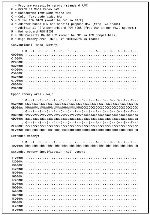
Note To save space, this map stops after the end of the second megabyte. In reality, however, this map continues to the maximum of addressable memory. Upper Memory Area (UMA)The term UMA describes the reserved 384KB at the top of the first megabyte of system memory on a PC/XT and the first megabyte on an AT-type system. This memory has the addresses from A0000 through FFFFF. The way the 384KB of upper memory is used breaks down as follows:
Not all the 384KB of reserved memory is fully used on most 16-bit and higher systems. For example, according to the PC standard, reserved video RAM begins at address A0000, which is right at the 640KB boundary. Normally, it is used for VGA graphics modes, whereas the monochrome and color text modes use B0000B7FFF and B8000BFFFF, respectively. Older non-VGA adapters used memory only in the B0000 segment. Different video adapters use varying amounts of RAM for their operations, depending mainly on the mode they are in. To the processor, however, it always appears as the same 128KB area, no matter how much RAM is really on the video card. This is managed by bank-switching areas of memory on the card in and out of the A0000BFFFF segments. The remainder of the memory in this area is reserved for motherboard and option ROM and for RAM memory on other types of add-on cards. Protected-mode operating systems do not load drivers into this area, as was common with DOS. The amount of free UMA space varies from system to system, depending mostly on the adapter cards installed on the system. For example, most video adapters, SCSI adapters, and some network adapters require some of this area for built-in ROM or special-purpose RAM use. Video RAM MemoryA video adapter installed in a system uses a portion of the system's first megabyte of memory to hold graphics or character information for display, but this typically is used or active only when in basic VGA mode. Whether the video adapter is built into the motherboard, part of the motherboard chipset, or plugs into an expansion slot, all modern video adapters emulate a standard VGA adapter card. The video BIOS appears in the first 32KB of segment C000. The built-in video circuit in these systems can in many cases be disabled with a switch or jumper, or sometimes by simply plugging in a video card. When the built-in VGA acts as though it were a separate card, disabling it allows a new adapter to be installed without any compatibility problems that might arise if the video drivers were incorporated into the motherboard BIOS. Adapter ROM and Special-Purpose RAM MemoryThe second 128KB of the UMA, beginning at segment C000, is reserved for the software programs, or BIOS, on the adapter boards plugged in to the system slots. These BIOS programs are stored on special chips known as ROM. Most adapters today use EEPROM or flash ROM, which can be erased and reprogrammed right in the system, without requiring the removal of the chip or card. Updating flash ROM is as simple as running the update program you get from the manufacturer and following the directions onscreen. It pays to check periodically with your card manufacturers to see whether they have flash ROM updates for their cards. ROM is useful for semipermanent programs that must always be present while the system is running, and especially for booting. On a server, the most likely devices to use this address space include SCSI BIOS, ATA RAID or SATA RAID BIOS, and some network adapter cards (BIOS or RAM). Thanks to plug-and-play configuration used by PCI devices and supported by recent server operating systems such as Windows 2000 Server and newer versions, there is little need to worry about ROM conflicts. However, if you are managing an older server using Windows NT 4.0, you might need to manually configure adapter cards with onboard BIOS ROM or option RAM to avoid conflicts. If these systems use ISA cards, you might need to adjust DIP switches or jumpers to set address ranges. With PCI cards, you can use a configuration program provided by the card vendor. Hard Disk Controller and SCSI Host Adapter BIOSThe UMA addresses C0000DFFFF are also used for the built-in BIOS contained on many hard drive and SCSI controllers. Table 5.2 lists the amount of memory and the addresses commonly used by the BIOS contained on hard drive adapter cards.
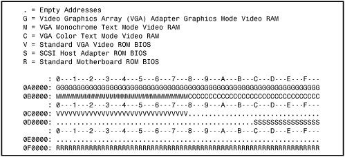
Note that integrated SCSI or ATA/SATA RAID adapters also use these same ranges. However, if the ATA or SATA RAID function is integrated into the motherboard's South Bridge chip, the standard motherboard BIOS rather than an add-on BIOS configures the host adapter, and no additional BIOS address space is used. The hard drive or SCSI adapter card used on a particular system might use a different amount of memory, but it is most likely to use the memory segment beginning at C800 because this address is considered part of the IBM standard for personal computers. Virtually all the disk controller or SCSI adapters today that have onboard BIOS allow the BIOS starting address to be easily moved in the C000 and D000 segments. The locations listed in Table 5.2 are only the default addresses that most of these cards use. If the default address is already in use by another card, you have to consult the documentation for the new card to see how to change the BIOS starting address to avoid any conflicts. Figure 5.2 shows a sample memory map for an Adaptec AHA-2940 SCSI adapter. Figure 5.2. Adaptec AHA-2940U SCSI adapter default memory use. Network AdaptersNetwork adapter cards can also use upper memory in segments C000 and D000. The exact amount of memory used and the starting address for each network card vary with the card's type and manufacturer. Some network cards do not use any memory at all. A network card might have two primary uses for memory:
IPL ROM is usually an 8KB ROM that contains a bootstrap loader program that enables the system to boot directly from a file server on the network. This enables the removal of all disk drives from the PC, creating a diskless workstation. Because no floppy or hard disk is in the system to boot from, IPL ROM gives the system the instructions necessary to locate an image of the operating system on the file server and load it as though it were on an internal drive. Network adapters that include IPL ROM are usually identified as supporting PXE (preboot execution environment). Shared memory refers to a small portion of RAM contained on the network card that is mapped into the PC's UMA. This region is used as a memory window onto the network and offers rapid data transfer from the network card to the system. Network adapters that do not use shared memory use DMA or programmed I/O (PIO) transfers to move data to and from the network adapter. However, most high-performance adapters use shared memory. Depending on the adapter, the shared memory range is usually 16KB in size and can be located at any user-selected 4KB increment of memory in segments C000 or D000 in conventional memory. Some network adapters use memory addresses above 1MB to avoid conflicts with other devices. Motherboard BIOS MemoryThe last 128KB of reserved memory is used by the motherboard BIOS. The BIOS programs in ROM control the system during the boot-up procedure and remain as drivers for various hardware in the system during normal operation. Because these programs must be available immediately, they can't be loaded from a device such as a disk drive.
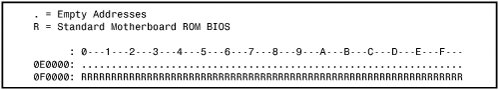
Both segments E000 and F000 in the memory map are considered reserved for the motherboard BIOS, but only some systems actually use this entire area. Most 16-bit or greater systems use all F000 for the BIOS and might decode but not use any of segment E000. By decoding an area, the motherboard essentially grabs control of the addresses, which precludes installing any other hardware in this region. In other words, configuring adapter cards to use this area isn't possible. This is why most adapters that use memory simply do not allow any choices for memory use in segment E000. Figure 5.3 shows the motherboard ROM BIOS memory use of most 16-bit or greater systems. Figure 5.3. The motherboard ROM BIOS memory use of most systems. Note that the standard system BIOS uses only segment F000 (64KB). Extended MemoryAs mentioned previously in this chapter, the memory map on a system based on a 286 or higher processor can extend beyond the 1MB boundary that exists when the processor is in real mode. For a system to address memory beyond the first megabyte, the processor must be in protected mode. Extended memory is basically all memory past the first megabyte, and it can be accessed only while the processor is in protected mode. Systems based on the Pentium Pro, Pentium II, and newer 32-bit server processors have a limit of 64GB (65,536MB, using 36-bit addressing) of system memory. Note 36-bit memory addressing is enabled through a method called physical address extension (PAE). PAE is an Intel-provided memory address extension that enables support of up to 64GB of physical memory for applications running on most 32-bit Intel Pentium Pro and later processors. PAE enables the processor to expand the number of bits that can be used to address physical memory from 32 bits to 36 bits, but it requires operating system support as well. Support for PAE is provided only in server-oriented operating systems such as Windows 2000 and later versions of the Advanced Server and Datacenter Server operating systems. Without PAE support, memory addressing is limited to 32 bits, or 4GB of physical RAM. Preventing ROM BIOS Memory Conflicts and OverlapAs explained previously, C000 and D000 are reserved for use by adapter-board ROM and RAM. If two adapters have overlapping ROM or RAM addresses, usually neither board operates properly. Each board functions if you remove or disable the other one, but they do not work together. This type of conflict is most likely to occur on servers running Windows NT 4.0 or servers that use ISA-slot expansion cards or integrated ISA devices that do not support plug-and-play configuration. To resolve conflicts, you can change the actual memory locations to be used with jumpers or switches or the adapter card or by using the adapter card's driver software. This type of conflict can cause problems for troubleshooters. You must read the documentation for each adapter to find out which memory addresses the adapter uses and how to change the addresses to allow coexistence with another adapter. Most of the time, you can work around these problems by reconfiguring the board or by changing jumpers, switch settings, or software-driver parameters. This type of change enables the two boards to coexist and stay out of each other's way. Similarly, if you must configure adapter boards manually, you must ensure that adapter boards do not use the same IRQ, DMA channel, or I/O port address. You can easily avoid adapter board memory, IRQ, DMA channel, and I/O port conflicts by creating a chart or template that mocks up the system configuration by penciling on the template the resources already used by each installed adapter. You end up with a picture of the system resources and the relationship of each adapter to the others. With Windows NT 4.0, you must ensure that the resources Windows lists for the device are those it actually uses. You should print out all the settings in your system before and after you make modifications to see what is changed. This can help you anticipate conflicts and ensures that you configure each adapter board correctly the first time. The template also becomes important documentation when you consider new adapter purchases because new adapters must be configurable to use the available resources in your system. Plug-and-play server operating systems such as Windows 2000 Server and Windows Server 2003 feature the Device Manager, which can be used to view and print out device settings, and most servers running these operating systems no longer contain ISA cards. These systems resolve almost all potential conflicts automatically by dynamically reconfiguring hardware to use nonconflicting memory address ranges.
ROM ShadowingVirtually all 386 and higher systems enable you to use what is termed shadow memory for the motherboard and possibly some adapter ROM as well. Shadowing essentially moves the programming code from slow ROM chips into fast 32-bit system memory. Shadowing slow ROM by copying its contents into RAM can greatly speed up these BIOS routinessometimes making them four to five times faster. Note that shadowing ROM is not very important when running a 32-bit operating system, such as Windows NT, Windows 2000 Server, or Windows Server 2003. This is because those operating systems use the 16-bit BIOS driver code only during booting; then they load 32-bit replacement drivers into faster extended memory and use them. Therefore, shadowing normally affects only DOS or other 16-bit software and operating systems. Because of this, some people are tempted to turn off the Video BIOS shadowing feature in the BIOS Setup. Unfortunately, doing so does not gain you any memory back (you've lost it anyway), and it in fact makes the system slightly slower to boot up and somewhat slower when in Windows safe mode. The 16-bit BIOS video driver code is used at those times. Adapter Memory Configuration and OptimizationAdapter boards use upper memory for their BIOS and as working RAM. If two boards attempt to use the same BIOS area or RAM area of upper memory, a conflict occurs that can keep the system from booting. In most cases, the plug-and-play software in the operating system ensures that such cards are automatically reconfigured so that they are not in conflict; however, sometimes problems can occur, and you must step in and manually resolve a conflict. The following sections cover ways to avoid these potential unresolved conflicts and how to troubleshoot if they do occur. In addition, these sections discuss moving adapter memory to resolve conflicts and provide some ideas on optimizing adapter memory use. How to Determine What Adapters Occupy the UMAYou can determine which adapters are using space in upper memory in the following two ways:
The simplest way (although by no means always the most foolproof) is to use a software utility to determine the UMAs used by the adapters installed on your system. You use the Device Manager in Windows 2000 Server or Windows Server 2003. You access it through the System properties sheet in the Control Panel. Device Manager examines your system configuration and determines not only the upper memory used by your adapters but also the IRQs used by each of these adapters. True plug-and-play systems also shut down one of the cards involved in a conflict to prevent a total system lockup. This could cause Windows to boot in safe mode. After you run Device Manager, or another utility to determine your system's upper memory configuration, you should make a printout of the memory addresses used. Thereafter, you can quickly refer to the printout when you are adding a new adapter to ensure that the new board does not conflict with any devices already installed on your system. Different Linux distributions use different methods of viewing and controlling hardware. For example, SUSE uses a hardware configuration utility called YaST. Red Hat Fedora uses a collection of tools stored in the System Settings submenu. Mandriva (formerly Mandrake) uses the drakconf or harddrake2 tools. See the documentation for your Linux distribution for details. Moving Adapter Memory to Resolve ConflictsPlug-and-playbased operating systems such as Windows 2000, Windows XP, and Windows Server 2003, as well as recent versions of Linux, automatically reallocate memory locations and other settings on plug-and-play hardware. Consequently, it's rare to encounter an adapter memory conflict. If necessary, you can move a card with a conflicting resource to another expansion slot. However, if you support older servers that use a nonplug-and-play operating system, such as Windows NT 4.0, or servers that contain ISA cards, you might need to manually configure cards to avoid conflicts. After you identify a conflict or potential conflict by using one of the two methods discussed in the previous section, you might have to reconfigure one or more of your adapters to move the upper memory space used by a problematic adapter. Most nonplug-and-play adapter boards make moving adapter memory a somewhat simple process in which you simply change a few jumpers or switches to reconfigure the board. With plug-and-play cards in a nonplug-and-play system, you can use the configuration program that comes with the board to make the changes. The following steps help you resolve most problems that arise because adapter boards conflict with one another:
For example, if one adapter uses the upper memory range C8000CBFFF and another adapter uses the range CA000CCFFF, you have a potential address conflict. One of them must be changed. Note that plug-and-play cards running in a plug-and-playbased operating system and motherboard allow these changes to be made directly from the Windows Device Manager. |
EAN: 2147483647
Pages: 240