Motherboard Types and Form Factors
| Several common form factors are used for server motherboards. The form factor refers to the physical dimensions (size and shape) as well as certain connector, screw holes, and other positions that dictate into which type of case the board will fit. Some are true standards (meaning that all boards with that form factor are interchangeable), whereas others are not standardized enough to allow for interchangeability. Unfortunately, these nonstandard form factors preclude any easy upgrade or inexpensive replacement, which generally means they should be avoided. The most commonly known obsolete motherboard form factors used for servers include the following:
The most commonly known current and emerging motherboard form factors used for servers include the following, listed according to form factor type: Small form factor:
Tower and pedestal:
Rack-mounted:
Note that some form factors fall into more than one category. Before 1996, low-cost servers that used industry-standard form factors typically used motherboards based on the Baby-AT form factor, a reduced-size version of the AT motherboard used in the IBM AT PC introduced in 1984. Starting in 1996, standards-based server motherboards began to use the ATX form factor, the larger extended ATX, or, in rare instances, the reduced-size microATX design. Starting in 2005, servers based on the BTX form factor were introduced. BTX is an evolutionary development of ATX that provides for better thermal management of high-performance systems. Although ATX and extended ATX are the most common server platforms for low-cost entry-level servers, starting in the late 1990s, Intel, in cooperation with Dell, IBM, and Silicon Graphics (SGI), developed a series of form factors especially designed for servers. These form factors are known collectively as Server System Infrastructure (SSI), and they support small form factor, pedestal, and rack-mounted servers. SSI form factors are used widely in entry-level servers based on x86 processors. Other server form factors considered in this chapter include the PICMG family of standards, which are used primarily in specialized industries such as telecommunications, blade servers, and various proprietary designs used for high-capacity rack-mounted and pedestal servers. Although there are no de facto or official standards for blade servers, blade server designs represent a significant development in server architecture. Some server form factors developed since the replacement of Baby-AT by newer designs have already been superseded. The SSI MEB form factor was designed to support up to four-way slot-mounted processors such as the Pentium III Xeon. With the development of more compact socketed processors, most vendors no longer use SSI MEB in its original form. Although some vendors use motherboards that have the same dimensions as SSI MEB, the motherboards are now designed for up to eight-way socketed server processors, such as the AMD Opteron. WTX was designed for workstations and medium-duty servers but never became popular. WTX motherboards today actually fit in Extended ATX cases. Because most x86-based servers on the market today use one of the industry-standard form factors listed in this section, you can upgrade such servers by replacing the motherboard. You can replace an ATX motherboard with a more advanced ATX motherboard, an SSI EEB motherboard with a more advanced SSI EEB motherboard, and so forth. As long as the chassis and power supply provide the necessary thermal and power requirements for the new processors and memory installed on the new motherboard, you can create a like-new server as an alternative to purchasing a brand-new server platform. If you are building your own server, you need to make sure you use an industry-standard form factor. (Each of these form factors is discussed in more detail in the following sections.) Form factors affect how much internal hardware a server can contain, and, in some cases, whether or how easily a server can be rack-mounted. Generally, servers based on SSI, PICMG, or blade server form factors are designed for or can be converted to rack-mounted form factors. Tip If you are planning to switch from a pedestal to a rack-mounted server in the next 24 months or less, purchase a pedestal server that can be converted to a rack-mounted server. Many vendors make pedestal servers or chassis that also support rack-mounting. Anything that does not fit into one of the industry-standard form factors should be considered proprietary. Although it is possible to build up to an eight-way server by using off-the-shelf server components, the reality is that many four-way and larger servers are proprietary. If you need an eight-way or larger server, you should evaluate the vendor-provided upgrade paths available if you plan to use the server long enough to need a new generation of memory or processor options. Also, you should determine how spare parts are provided. Can you obtain them from more than one source, or must you use the vendor's own service department? These considerations will help you find the best fit in terms of serviceability and long life for a server you cannot upgrade with standard components. ATX MotherboardsAlthough some vendors built servers based on the original IBM XT and AT motherboard form factors (AT and Baby-AT) from the 1980s through the mid-1990s, all servers using these form factors are long obsolete, and most of them have been replaced. Thus, the first form factor we consider in detail is the ATX form factor. Intel initially released the official ATX specification in July 1995. It was written as an open specification for the industry. ATX boards didn't hit the market in force until mid-1996, when they rapidly began replacing Baby-AT boards in new systems. The ATX specification was updated to version 2.01 in February 1997, 2.03 in May 2000, 2.1 in June 2002, and 2.2 in February 2004. Intel publishes these detailed specifications so other manufacturers can use the interchangeable ATX design in their systems. The current specifications for ATX and other current motherboard types are available online from the Desktop Form Factors site: www.formfactors.org. ATX is the most popular motherboard form factor for new entry-level and midrange servers through at least 2006. An ATX system will be upgradable for many years to come, exactly as Baby-AT was in the past. Note Although many major server OEMs build machines that appear to meet the ATX form factor specifications, they may use proprietary cases or power supply designs to limit your upgrade options. If you want maximum flexibility, consider building your own server, based on ATX or SSI form factors. The major features of an ATX motherboard include the following:
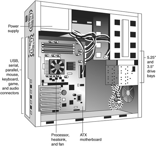
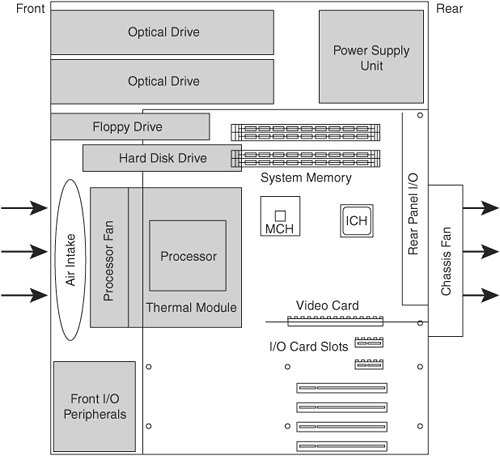
Figure 4.1 shows the ATX system layout and chassis features of a typical entry-level server, as you would see them looking sideways in a tower with the side panel removed. Notice how virtually the entire motherboard is clear of the drive bays and how the devices such as CPU, memory, and internal drive connectors are easy to access and do not interfere with the bus slots. Also notice how the processor is positioned near the power supply. Figure 4.1. When mounted inside the case, the ATX motherboard is oriented so that the CPU socket is near the power supply fan and case fan (if the case includes one). The ATX motherboard shape is basically a Baby-AT design rotated sideways 90°. Compared to a Baby-AT design, the expansion slots are now parallel to the shorter side dimension and do not interfere with the CPU, memory, or I/O connector sockets (see Figure 4.2). There are actually two basic sizes used by ATX-based servers:
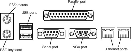
Figure 4.2. ATX specification 2.2 motherboard dimensions.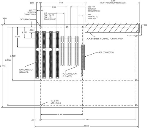 MiniATX was once an official specification, but starting with ATX 2.1, it was dropped. Extended ATX was never part of the official ATX specification. Because it is substantially deeper than either ATX or MiniATX, an Extended ATX motherboard will not fit in some of the smaller ATX cases. Be sure to check with the case vendor if you are building a server based on an Extended ATX board or if you are upgrading an existing server. Although the case holes are similar to those in the Baby-AT case, cases for Baby-AT and ATX are generally incompatible. The ATX power supply design is identical in physical size to the standard slimline power supply used with Baby-AT systems; however, they also use different connectors and supply different voltages. If you are considering replacing the motherboard in an existing server, the best way to tell if it has an ATX-family motherboard design without removing the lid is to look at the back of the system. Two distinguishing features identify ATX. One is that the expansion boards plug directly in to the motherboard. There is usually no riser card, as with LPX or NLX form factors, so the slots are perpendicular to the plane of the motherboard. Also, ATX boards have a unique double-high connector area for all the built-in connectors on the motherboard (see Figure 4.3 and Table 4.1). This is located just to the side of the bus slot area and can be used to easily identify an ATX board. Figure 4.3. ATX motherboard and rear panel connections from a typical server with dual Ethernet ports and integrated video.
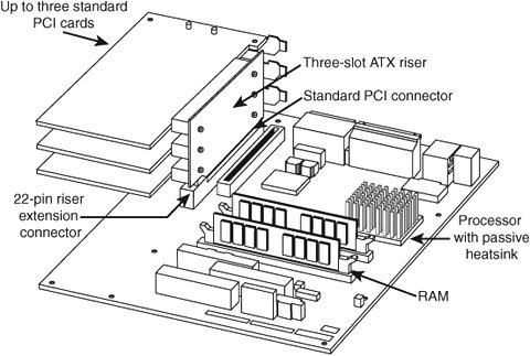
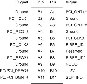
Note Most ATX motherboards feature connectors with industry-standardized color codes (shown in Table 4.1). This makes plugging in devices much easier and more foolproof: You merely match up the colors. For example, most keyboards have a cable with a purple plug, whereas most mouse devices have a cable with a green plug. Even though the keyboard and mouse connectors on the motherboard appear the same (both are 6-pin mini-DIN types), their color-coding matches the plugs on the respective devices. Thus, to plug them in properly, you merely insert the purple plug into the purple connector and the green plug into the green connector. This saves you from having to bend down to try to decipher small labels on the connectors to ensure that you get them right. The ATX RiserIn December 1999, Intel introduced a riser card design modification for ATX motherboards. The design includes the addition of a 22-pin (2x11) connector to one of the PCI slots on the motherboard, along with a two- or three-slot riser card that plugs in. The riser enables two or three PCI cards to be installed, but it does not support AGP. The ATX riser design enables ATX motherboards to be used in 1U or 2U rack-mounted systems. Figure 4.4 shows an example of a riser card installation on an ATX-family motherboard. Note that if you use a riser card, you cannot use the remaining slots on the motherboard. Figure 4.4. A three-slot ATX riser implementation on a MicroATX motherboard. On motherboards that use a 22-pin extension connector, the riser is usually installed in line with PCI slot 6, which is the second one from the right; the slots are usually numbered from right to left (facing the board), starting with 7 as the one closest to the processor. It's useful to know the slot numbering scheme used by your server's motherboard in case of conflicts or card failures; check your system or motherboard documentation for details. The pinout of the ATX 22-pin riser extension connector is shown in Figure 4.5. Figure 4.5. An ATX 22-pin riser extension connector pinout. The PCI connector that is in line with the riser extension connector is just a standard PCI slot; none of the signals are changed. Some multislot riser cards can be plugged in to standard PCI slots: They use cables and special connectors to provide power and signaling to the second or third slots in a riser card. Some recent systems now support risers for PCI, PCI-X, and PCI-Express cards. PCI-X is backward compatible with PCI, so a PCI-X riser card can be used with either type of card. PCI-Express uses a different slot design and thus a different riser design. Systems that use the riser are generally low-profile designs. Therefore, they don't fit normal PCI or AGP cards in the remaining (non-riser-bound) slots. Although the ATX riser standard was originally developed for use with low-end boardswhich have integrated video, sound, and network supportmany rack-mounted servers are also using the ATX riser because these boards also have most of their required components already integrated. In fact, the ATX riser appears to be more popular for rack-mounted servers than for the originally intended target market of slimline desktop systems. Note A slimline case is a case that is thinner than a normal case. A standard ATX tower case is about 7 to 7.5 inches wide, and a slimline case is 2 or so inches narrower. ATX riser cards, compatible cases, and compatible motherboards are available from a variety of vendors, which means you can build your own slimline ATX system. The WTX Form FactorWTX was a board and system form factor developed for the midrange workstation market; however, most vendors making workstations and servers have used the ATX form factor. WTX went beyond ATX and defined the size and shape of the board and the interface between the board and chassis, as well as required chassis features. WTX was first released in September 1998 (1.0) and updated in February 1999 (1.1). The specification and other information on WTX used to be available at www.wtx.org; however, WTX has been officially discontinued, and there will be no further updates. WTX motherboards have a maximum width of 14 inches (356mm) and a maximum length of 16.75 inches (425mm), which is significantly larger than ATX. There are no minimum dimensions, so board designers are free to design smaller boards as long as they meet the mounting criteria. The additional space provided by the WTX form factor provides room for two or more processors and other onboard equipment needed in a workstation or server design. Although WTX is no longer an official form factor, a number of server and workstation motherboard vendors, such as Tyan, MSI, and SuperMicro, continue to build products that use it. In practice, current systems using WTX-sized motherboards are basically extensions of the ATX architecture. WTX motherboards use different power connectors than ATX motherboards. Originally, WTX motherboards used a 24-pin power connector that supplied only 5V and 3.3V power to the motherboard and a separate 22-pin power connector that supplied 12V power and control signals. Modern WTX motherboards still use a 24-pin primary power connector, but the connector might use the EPS12V (also known as the Superset ATX or SSI) standard or the older ATX-GES standard. Both ATX-GES and EPS12V provide 3.3V, 5V, and 12V power to the motherboard, but the pinouts are completely different. EPS12V motherboards also use an 8-pin power connector to provide additional 12V power to the processor(s).
SSI Form Factor SpecificationsAnother ATX-derived form factor is the Server System Infrastructure (SSI) group of specifications that Intel developed in cooperation with Dell, IBM, and Silicon Graphics. The SSI initiative, which began in 1998, provides the following specifications for power supplies:
The SSI initiative provides the following current specifications for electronic bays (chassis):
Although the SSI MEB specification is no longer current (it was designed to support slot-mounted processors), some vendors produce motherboards in this form factor to support four-way and larger servers. See Figure 4.8 in the next section. Table 4.2 compares the dimensions and other features of SSI motherboard form factors with ATX motherboard form factors.
Note For details on current and older versions of SSI specifications and information about products that meet those specifications, see the SSI website, at www.ssiforum.org. Table 4.3 provides examples of current products that correspond to each SSI form factor.
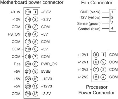
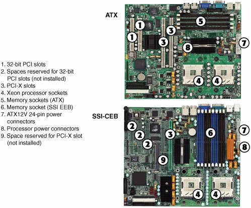
The EEB Form FactorThe EEB form factor has essentially the same shape as the Extended ATX form factor: 12 inches by 13 inches (305mmx330mm). Mounting holes used by EEB are the same as those used by ATX specification version 2.1. The I/O connector cluster is also the same as that for ATX. However, EEB supports a 24-pin power connector, following the EPS12V standard rather than the 20-pin ATX power connector standard used on older ATX motherboards. Like ATX, EEB supports up to seven expansion slots. Another difference between EEB and ATX is EEB's inclusion of an 8-pin 12V power connector for processor power and a 4-pin connector for cooling fans. The additional pin provides control as well as voltage, ground, and sensing features found in 3-pin fan connectors on ATX motherboards. The EEB standard recommends at least five motherboard fan connectors and as many as eight in rack-mounted implementations. The EEB 24-pin main power connector, 8-pin 12V power connector, and 4-pin cooling fan pinouts are illustrated in Figure 4.6. Figure 4.6. SSI EEB motherboard (top), processor (lower right), and fan (upper right) power connectors. The CEB Form FactorThe CEB form factor is similar to the EEB form factor, but the maximum motherboard dimensions are reduced to 12 inchesx10.5 inches (305mmx267mm). Thus, CEB falls between the ATX and EEB form factors in overall dimensions. It uses the same mounting holes as ATX specification version 2.2. The same power and fan connectors shown in Figure 4.6 are also part of the CEB specification. Figure 4.7 illustrates a typical SSI CEB-compatible motherboard that is optimized for rack-mounted use compared to a typical ATX motherboard. Note the empty spaces reserved for PCI and PCI-X expansion slots; this model uses a riser card for add-on cards. Similar models designed for pedestal servers include the expansion slots not shown in this example. Figure 4.7. A typical dual-CPU ATX motherboard (top) compared to an SSI CEB motherboard optimized for 1U/2U rack-mounting (bottom). As you can see from Figure 4.7, an SSI-CEB and an ATX motherboard can have similar features. However, the SSI-CEB motherboard generally has provision for more memory sockets than an ATX motherboard and is a slightly different size (refer to Table 4.2). The TEB Form FactorUnlike other SSI specifications, the latest version of the TEB specification, version 2.11, is tailored to the requirements of Intel 64-bit Xeon processors and motherboards based on the E7320, E7520, and E7525 chipsets. TEB is a specification optimized for 1U and 2U rack-mounted servers.
The size of a TEB version 2.11 motherboard is the same as that used by the latest version of EEB: 12 inches by 13 inches (305mmx330mm). Mounting holes used by TEB are the same as those used by ATX specification version 2.1. TEB, unlike EEB and CEB, uses a riser card slot that supports up to three 2U cards or one 1U card rather than multiple PCI, PCI-X, or PCI-Express slots. The riser card connector type is not defined, so a motherboard designer can choose the appropriate type of riser card and slot to use for the job. TEB motherboards use the same power and fan connectors supported by EEB and CEB motherboards (refer to Figure 4.6). TEB motherboards for 2U rack-mounted servers use the same type of I/O port cluster as ATX motherboards, while 1U rack-mounted servers use a thinner version. The MEB Form FactorMEB was designed in 1999, at a time when most server processors used bulky Slot 1 or Slot 2 designs. Thus, the MEB form factor has dimensions of 13 inches (330mm) by 16 inches (406.4mm), and it supports up to 10 expansion slots, as well as a memory riser board slot. This standard is now officially obsolete, but some vendors continue to build products based on the MEB standard, primarily for four-way systems. Note Some vendors mislabel MEB form factor motherboards as corresponding to the EEB 3.5 standard. To avoid confusion, you should look at the actual dimensions of the motherboard in question. If you are considering motherboards that correspond to the Extended ATX, EEB, or MEB form factors, you should be sure to get a list of recommended enclosures from the motherboard vendor. MEB form factor motherboards do not fit into ATX cases. Figure 4.8 compares a typical ATX server motherboard (left) to an MEB server motherboard (right). Figure 4.8. The Tyan Tiger i7501 (S2723) motherboard (left) uses the ATX form factor, whereas the Tyan Thunder K8QS Pro (S4882) motherboard (right) uses the SSI MEB form factor. Photos courtesy of Tyan Computer Corporation.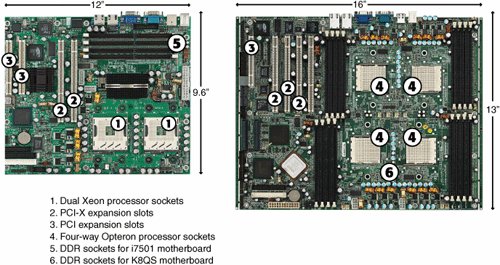 Backplane SystemsEver since the first IBM PC was introduced in 1981, the vast majority of PCs and servers have placed major components such as the processor (CPU), chipset, and memory on the motherboard. Expansion slots were used for I/O and display devices. However, some servers and PCs have used a different type of design, known as a backplane system. These systems do not have a motherboard in the true sense of the word. In a backplane system, the components typically found on a motherboard are located instead on one or more expansion adapter cards plugged in to slots. In these systems, the board with the slots is called a backplane, rather than a motherboard. Systems that use this type of construction are called backplane systems. Backplane systems enable faster swapping of failed components than motherboard-based systems, easier upgrading to faster processors and memory (you swap a single board to make the change), and greater reliability in industrial environments. Backplane systems come in two main types: passive and active. In a passive backplane, the main backplane board does not contain any circuitry at all except for the bus connectors and maybe some buffer and driver circuits. All the circuitry found on a conventional motherboard is contained on one or more expansion cards installed in slots on the backplane. Some backplane systems use a passive design that incorporates the entire system circuitry into a single mothercard. The mothercard is essentially a complete motherboard designed to plug in to a slot in the passive backplane. The passive backplane/mothercard concept enables you to easily upgrade the entire system by changing one or more cards. The major examples of passive backplane systems in use today include PICMG-based single-board computers and various types of blade servers. In an active backplane, the main backplane board contains bus control and usually other circuitry as well. Most active backplane systems contain all the circuitry found on a typical motherboard except for the processor complex. The processor complex is the circuit board that contains the main system processor and any other circuitry directly related to it, such as clock control, cache, and so forth. The processor's complex design enables the user to easily upgrade the system later to a new processor type by changing one card. In effect, it amounts to a modular motherboard with a replaceable processor section. Although servers built by IBM, Compaq, and ALR (later absorbed into Gateway) have used this type of design, this type of backplane design is no longer used due to the expense of proprietary processor boards and the advent of easy industry-standard processor upgrades through zero insertion force (ZIF) sockets. PICMG BackplanesPICMG has developed a series of specifications for passive-backplane computers for industrial use, including servers. These specifications are listed in Table 4.4.
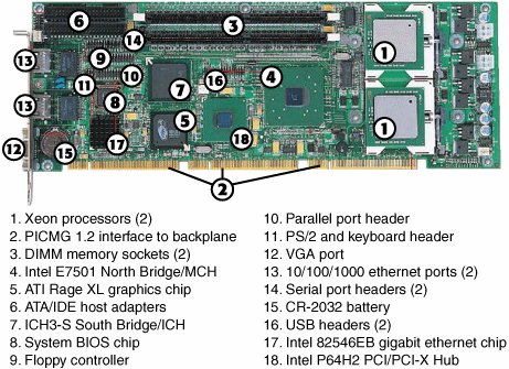
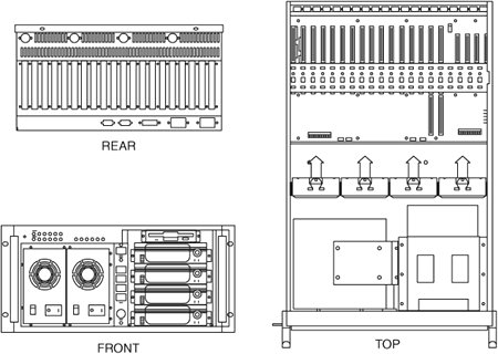
Passive backplane systems with mothercards (often called single-board computers [SBCs]) are by far the most popular backplane design. They are used in industrial or laboratory-type systems and are rack mountable. They usually have a large number of slots and extremely heavy-duty power supplies; they also feature high-capacity, reverse flow cooling designed to pressurize the chassis with cool, filtered air. Many passive backplane systems, such as the one pictured in Figure 4.9, adhere to the ePCI-X passive backplane form factor standard set forth by PICMG. You can get more information about these standards from PICMG's website, at www.picmg.org. Figure 4.9. A typical Xeon PICMG single-board computer. This single card provides PCI and PCI-X interfacing; integrated video; 2 Gigabit Ethernet (10/100/1000) network interfaces; and normal parallel, serial, ATA/IDE, USB, and floppy interfaces. Figure 4.9 shows a typical dual-Xeon single-board computer used in PICMG 1.2 ePCI-X passive backplane systems. Figure 4.10 shows a rack-mounted chassis with a passive backplane. Figure 4.10. A rack-mounted chassis with passive backplane. Blade ServersBlade servers are the latest development of passive-backplane technology. Multiple server blades of various types can be connected to a single blade server enclosure. A server blade is a self-contained computer that contains one or more processors, memory, and storage. It differs from a PICMG single-board computer in several ways:
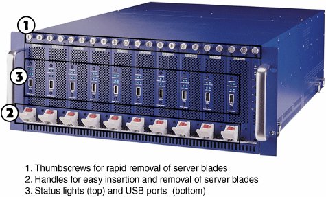
Typical sizes for blade servers include 1U (1.75 inches high) and 3U (5.25 inches high); 3U and larger units permit more flexibility in storage solutions. Figure 4.11 illustrates two of the many different server blades available, and Figure 4.12 illustrates a blade server enclosure. Figure 4.11. Some typical server blades.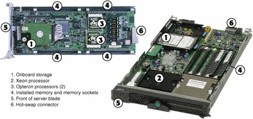 Figure 4.12. A typical fully populated server blade chassis. Figures 4.11 and 4.12 make it clear that, unlike traditional and rack-mounted servers that use motherboards or PICMG single-board computers, there is no true standard for blade server technology. Each developer of blade servers uses its own proprietary design for the blades, the chassis, and the I/O and network modules.
BTX MotherboardsBTX is a motherboard form factor specification Intel originally released in September 2003, with a 1.0a update in February 2004. BTX may eventually replace the venerable ATX form factor while addressing ever-increasing component power and cooling requirements, as well as enabling improved circuit routing and more flexible chassis designs. BTX represents a completely new form factor that is not backward compatible with ATX or other designs. A full-size BTX board is 17% larger than an ATX board, allowing room for more integrated components onboard. The I/O connectors, slots, and mounting holes are in different locations than with ATX, requiring new chassis designs. However, the power supply interface connectors are the same as in the latest ATX12V specifications, and newer ATX, TFX, SFX, CFX, and LFX power supplies can be used. The latter two power supply form factors were specifically created to support compact and low-profile BTX systems. The primary advantages of BTX include the following:
BTX includes three definitions of motherboard size, as shown in Table 4.5.
Each board has the same basic screw hole and connector placement requirements. So if you have a case that fits a full-size BTX board, you can also mount a MicroBTX or picoBTX board in that same case (see Figure 4.13). Obviously, if you have a smaller case designed for MicroBTX or picoBTX, you can't put the larger MicroBTX or BTX boards in that case. Figure 4.13. BTX specification 1.0a motherboard dimensions.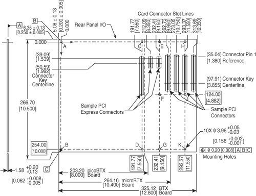 BTX requires up to 10 mounting holes and supports up to seven slots, depending on the size, as shown in Table 4.6.
BTX also clearly specifies volumetric zones around the motherboard to prevent any interference from the chassis or internal components, such as drives, which allows for maximum interchangeability without physical interference or fit problems. With processors exceeding 100W in thermal output, as well as voltage regulators, motherboard chipsets, and video cards adding to the thermal load in a system, BTX was designed to allow all the high-heat-producing core components to be mounted inline from front to back so that a single high-efficiency thermal module (heatsink) can cool the system. This eliminates the need for an excessive number of fans. The thermal module includes a heatsink for the processor, a high-efficiency fan, and a duct to direct airflow through the system. Extra support for the thermal module is provided under the board via a support and retention module (SRM), which provides structural support for heatsinks that are much heavier than allowed in ATX designs. The thermal module pulls air directly from the front of the case over the processor and memory for better cooling than with ATX systems. BTX uses the same power connectors as in the latest ATX12V v2.x power supply form factor specifications, including a 24-pin main connector for the board and a 4-pin ATX12V connector for the CPU voltage regulator module. The particular power supply form factor used depends mostly on the chassis selected. A typical tower system has components arranged as shown in Figure 4.14. Figure 4.14. BTX tower chassis layout. From Figure 4.14, you can see that the main heat-producing core components are centrally located inline from front to rear, allowing the most efficient thermal design. Air flows from front to rear through the center, cooling the processor, motherboard chipset, memory, and video card. To support the heavy processor heatsink and thermal module assembly, an SRM is mounted under the board. The SRM is essentially a metal plate affixed to the chassis under the board, and the thermal module is bolted directly to the SRM instead of to the motherboard. This helps carry the weight of the module and prevents excessive loads from being applied to the processor and motherboard, especially during the shipping and handling of the system. The BTX I/O connector area is similar to ATX, except that it is at the opposite side of the rear of the board. The size of the area is slightly shorter but wider than ATX, allowing a large number of interfaces and connectors to be built in to the motherboard. As of early 2006, only a few BTX servers were available in the marketplace. It remains to be seen whether BTX will replace ATX at some point or will become unnecessary as both Intel and AMD introduce lower-wattage processors in 2006 and beyond. Proprietary Server DesignsProprietary server designs aren't limited to the world of blade servers. Many four-way and almost all eight-way or larger servers use proprietary designs. There are several reasons for this:
For these reasons, proprietary designs have been and will continue to be popular. All servers running RISC processors are, by definition, proprietary. Itanium-based processors also use proprietary designs. However, systems running x86 processors might also feature proprietary designs. Table 4.7 lists some of the major proprietary server designs available from major vendors.
One of the benefits of considering proprietary server designs is the greater emphasis on redundancy and hot-swapping of defective hardware that is possible. While many midrange and high-end servers feature various levels of fault-tolerant design, such as hot-swap memory, fans, and drives, it's still possible for a failure in another part of the server to cripple the unit or shut it down entirely. If your business depends on true 24x7x365 reliability from a server, you might want to consider a server that replicates every major component and processes information in parallel. This type of server is known as a fault-tolerant server. Fault-Tolerant ServersBecause fault-tolerant servers process information in parallel, using two or three replicated systems in one, a failure in one part of the server does not cause data loss or even require a shutdown; the parallel components continue to work and provide the information needed. Major vendors of fault-tolerant servers include Stratus, NEC, and Hewlett-Packard. Their products are discussed in the following sections. Stratus ftServer and Continuum ServersStratus (www.stratus.com) offers several lines of fault-tolerant servers:
The ftServer W and T series are roughly comparable to the NEC Express5800 series (discussed in the next section). Because they run Windows Server 2003 or Linux, they would be easy to add to any network already running those operating systems. NEC Express5800 SeriesNEC (www.necsam.com) offers a line of fault-tolerant servers known as the Express5800 series. The Express5800 series offers both Linux and Windows Server 2003based systems with up to four-way Xeon processors. The Express5800 series uses technology licensed from Stratus. Hewlett-Packard Integrity NonStop SeriesHewlett-Packard (www.hp.com) offers a line of fault-tolerant servers known as the Integrity NonStop series. The Integrity NonStop series, introduced in 2005, differs from the previous NonStop series because it uses Intel Itanium 2 processors, whereas the previous NonStop servers used Silicon Graphics MIPS S88000 processors. Hewlett-Packard refers to its fault-tolerant design as NonStop Advanced Architecture (NSAA). NSAA is designed to provide fault tolerance at both software and hardware levels. Therefore, Integrity NonStop servers run a specially designed operating system and applications. The Integrity NonStop series is designed to handle much larger server tasks than the Stratus W or T series or the NEC Express5800 series, with scalability up to 4,080 processors and up to 64TB of memory. | |||||||||||||||||||||||||||||||||||||||||||||||||||||||||||||||||||||||||||||||||||||||||||||||||||||||||||||||||||||||||||||||||||||||||||||||||||||||||||||||||||||||||||||||||||||||||||||||||||||||||||
EAN: 2147483647
Pages: 240