Hack9.Reassemble Your PSP
Hack 9. Reassemble Your PSP
If your PSP is in pieces, you'll no doubt want to know how to put it back together again. Taking apart your PSP [Hack #8] is really only half of the puzzle. In fact, many have said that taking something apart is easy; putting it back together again is what really separates the wheat from the chaff. So, in this hack, I am going to provide you with the necessary instructions to get that torn-apart PSP back together again. Assuming you have not caused any permanent damage from spilt soda, four-foot drops, or a frustrated fist, when reassembled, your PSP should turn on and work as originally designed. 1.10.1. The Large Print, etc.At this point, you know your warranty is worthless and all bets are off as to what will happen when you finally put the battery pack back into the PSP and turn it on. However, that doesn't change the fact that you need to be cautious and use a delicate hand. Before continuing, please review "The Tools of the Trade" and "Critical Suggestions" sections in "Take Your PSP Apart" [Hack #8]. 1.10.2. Installing the Network CardThis step is fairly simple, with the only tricky part being the correct insertion of the WNIC (wireless network interface card)/Memory Stick circuit board. Be sure to take advantage of the many guide pins included in the PSP to ensure that you insert this component, and others, correctly. Figures 1-32 and 1-33 provide illustrations of the following steps. Figure 1-32. Inserting the wireless network card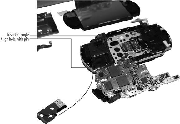 To install the network card:
Figure 1-33. Screw positions, WiFi switch, and separator alignment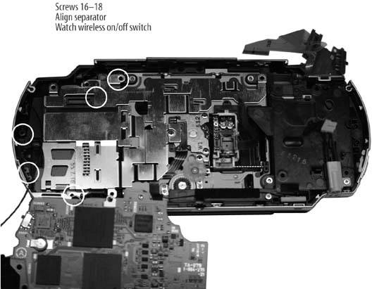 1.10.3. Installing the Main Circuit BoardThis section is the hardest part of reassembling the PSP. It can be a bit tedious to ensure that you have the board seated correctly, but patience is necessary. Pay attention to the critical areas highlighted in Figure 1-34. Figure 1-34. Critical areas to watch when installing the main circuit board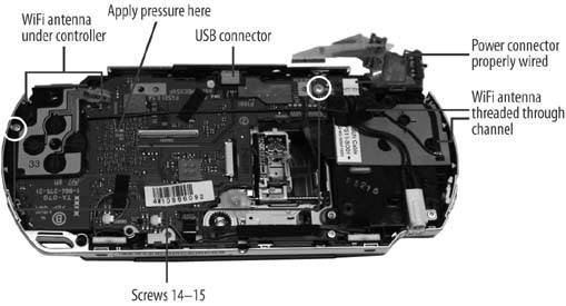 To install the main circuit board:
1.10.4. Installing the LCDYou are nearly there. The trickiest part of this step is to be sure that the LCD backlight power strip (the small one) is properly seated. You will note two small extensions on the sides of the strip near the end. These will come in handy when you attempt to seat the connecter. Figures 1-35 and 1-36 highlight the areas you will be working with when reinstalling the LCD. To reinstall the LCD:
Figure 1-35. Installing the LCD tray Figure 1-36. Installing the LCD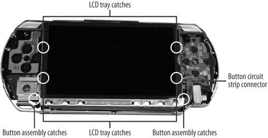 1.10.5. Putting the Buttons and Shell into PlaceYou're almost there! Try not to jump ahead and insert the battery just yet. Honestly, it is all downhill from here. Figure 1-23 earlier in the chapter provides you with an illustration of where to insert the final screws. Here's how to wrap things up:
1.10.6. Turning It On!It is now time to see whether you are the owner of a working PSP or a $250 paperweight. As you can see from Figure 1-37, my attempt was successful. However, I will admit that the first time I tried this, the PSP's backlight did not turn back on. I was still able to see the screen, but only in the right light and at the right angle. I suspect it was because I was testing various components out with the board exposed. I probably shorted out a circuit and fried some capacitor or diode. I learned my lesson, though, and have now successfully taken apart and reassembled a PSP. Figure 1-37. Turning it on!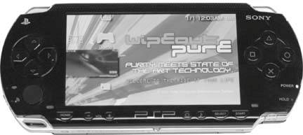 1.10.7. Hacking the HackNow that you know how to take apart and reassemble your PSP, make sure to check out all the hardware-related hacks in this book. Have fun voiding your warranty! Seth Fogie |
EAN: 2147483647
Pages: 108
- Chapter II Information Search on the Internet: A Causal Model
- Chapter V Consumer Complaint Behavior in the Online Environment
- Chapter VI Web Site Quality and Usability in E-Commerce
- Chapter X Converting Browsers to Buyers: Key Considerations in Designing Business-to-Consumer Web Sites
- Chapter XVII Internet Markets and E-Loyalty