Basic Hard Disk Drive Components
| Many types of hard disk drives are on the market, but nearly all share the same basic physical components. Some differences might exist in the quality of these components (and in the quality of the materials used to make them), but the operational characteristics of most drives are similar. The basic components of a typical hard disk drive are as follows:
You can see each of these components in Figure 9.9. Figure 9.9. Typical hard disk drive components.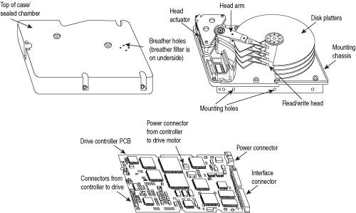 The platters, spindle motor, heads, and head actuator mechanisms usually are contained in a sealed chamber called the head disk assembly (HDA). The HDA is usually treated as a single component; it is rarely opened. Other parts external to the drive's HDA, such as the logic boards, bezel, and other configuration or mounting hardware, can be disassembled from the drive. Hard Disk Platters (Disks)A hard disk drive has one or more platters, or disks. Table 9.3 lists the hard disk drive form factors, the associated platter sizes that have been used in PC hard disk drives, and year they were first introduced:
As you can see from the table, the dimensions used in describing the form factors are approximations; the actual platter diameters are usually somewhat different. Earlier in the chapter, I listed the exterior dimensions of drives using these various form factors. Most hard disk drives have two or more platters, although some of the smaller drives used in portable systems have only one. The number of platters a drive can have is limited by the drive's vertical physical size. The maximum number of platters I have seen in any 3.5-inch drive is 12; however, most drives have six or fewer. Platters have traditionally been made from an aluminum/magnesium alloy, which provides both strength and light weight. However, manufacturers' desire for higher and higher densities and smaller drives has led to the use of platters made of glass (or, more technically, a glass-ceramic composite). One such material, produced by the Dow Corning Corporation, is called MemCor. MemCor is made of a glass-ceramic composite that resists cracking better than pure glass. Glass platters offer greater rigidity than metal (because metal can be bent and glass cannot) and can therefore be machined to one-half the thickness of conventional aluminum diskssometimes less. Glass platters are also much more thermally stable than aluminum platters, which means they do not expand or contract very much with changes in temperature. Several hard disk drives made by companies such as IBM, Western Digital, Seagate, Toshiba, and Maxtor currently use glass or glass-ceramic platters. In fact, Hitachi Global Storage Technologies (Hitachi and IBM's joint hard disk venture) is designing all new drives with only glass platters. For most other manufacturers as well, glass disks will probably replace the standard aluminum/magnesium substrate over the next few years. Recording MediaNo matter which substrate is used, the platters are covered with a thin layer of a magnetically retentive substance, called the medium, on which magnetic information is stored. Three popular types of magnetic media are used on hard disk platters:
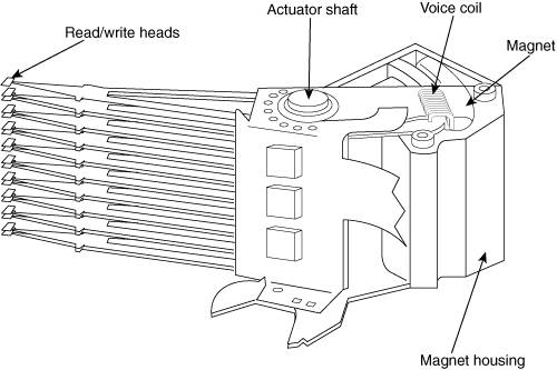
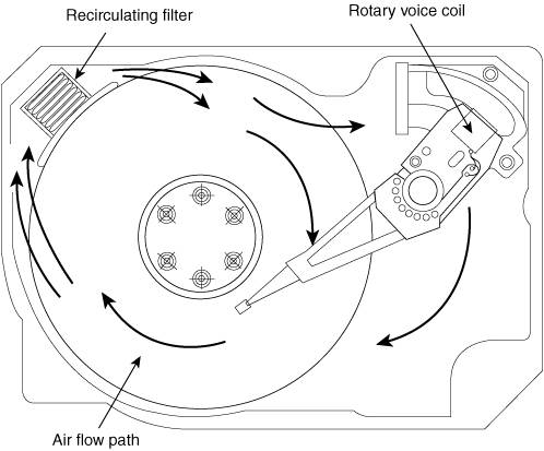
Oxide MediaThe oxide medium is made of various compounds, containing iron oxide as the active ingredient. The magnetic layer is created on the disk by coating the aluminum platter with a syrup containing iron-oxide particles. This syrup is spread across the disk by spinning the platters at a high speed; centrifugal force causes the material to flow from the center of the platter to the outside, creating an even coating of the material on the platter. The surface is then cured and polished. Finally, a layer of material that protects and lubricates the surface is added and burnished smooth. The oxide coating is normally about 30 millionths of an inch thick. If you could peer into a drive with oxide-coated platters, you would see that the platters are brownish or amber. As drive density increases, the magnetic medium needs to be thinner and more perfectly formed. The capabilities of oxide coatings have been exceeded by most higher-capacity drives. Because the oxide medium is very soft, disks that use it are subject to head-crash damage if the drive is jolted during operation. Most older drives, especially those sold as low-end models, use oxide media on the drive platters. Oxide media, which have been used since 1955, remained popular because of their relatively low cost and ease of application. Today, however, very few drives use oxide media. Thin-Film MediaThe thin-film medium is thinner, harder, and more perfectly formed than the oxide medium. Thin film was developed as a high-performance medium that enabled a new generation of drives to have lower head-floating heights, which in turn made increases in drive density possible. Originally, thin-film media were used only in higher-capacity or higher-quality drive systems, but today, virtually all drives use thin-film media. The thin-film medium is aptly named. The coating is much thinner than can be achieved by the oxide-coating method. Thin-film media are also known as plated or sputtered media because of the various processes used to deposit the thin film on the platters. Thin-film-plated media are manufactured by depositing the magnetic medium on the disk with an electroplating mechanism, in much the same way that chrome plating is deposited on the bumper of a car. The aluminum/magnesium or glass platter is immersed in a series of chemical baths that coat the platter with several layers of metallic film. The magnetic medium layer itself is a cobalt alloy about 1 µ-inch thick. Thin-film sputtered media are created by first coating the aluminum platters with a layer of nickel phosphorus and then applying the cobalt-alloy magnetic material in a continuous vacuum-deposition process called sputtering. This process deposits magnetic layers as thin as 1 µ-inch or less on the disk, in a fashion similar to the way that silicon wafers are coated with metallic films in the semiconductor industry. The same sputtering technique is then used again to lay down an extremely hard, 1 µ-inch protective carbon coating. The need for a near-perfect vacuum makes sputtering the most expensive of the processes described here. The surface of a sputtered platter contains magnetic layers as thin as 1 µ-inch. Because this surface also is very smooth, the head can float more closely to the disk surface than was possible previously. Floating heights as small as 10nm (nanometers, or about 0.4 µ-inch) above the surface are possible. When the head is closer to the platter, the density of the magnetic flux transitions can be increased to provide greater storage capacity. Additionally, the increased intensity of the magnetic field during a closer-proximity read provides the higher signal amplitudes needed for good signal-to-noise performance. Both the sputtering and plating processes result in a very thin, hard film of magnetic medium on the platters. Because the thin-film medium is so hard, it has a better chance of surviving contact with the heads at high speed. In fact, modern thin-film media are virtually uncrashable. If you could open a drive to peek at the platters, you would see that platters coated with the thin-film medium look like mirrors. AFC MediaThe latest advancement in drive media is called antiferromagnetically coupled (AFC) media, which is designed to allow densities to be pushed beyond previous limits. Any time density is increased, the magnetic layer on the platters must be made thinner and thinner. Areal density (tracks per inch times bits per inch) has increased in hard drives to the point where the grains in the magnetic layer used to store data are becoming so small that they become unstable over time, causing data storage to become unreliable. This is referred to as the superparamagnetic limit, which has been determined to be between 30 and 50Gbit/sq. in. Drives today have already reached 35Gbit/sq. in., which means the superparamagnetic limit is now becoming a factor in drive designs. AFC media consist of two magnetic layers separated by a very thin 3-atom (6 angstrom) film layer of the element ruthenium. IBM has coined the term "pixie dust" to refer to this ultra-thin ruthenium layer. This sandwich produces an antiferromagnetic coupling of the top and bottom magnetic layers, which causes the apparent magnetic thickness of the entire structure to be the difference between the top and bottom magnetic layers. This allows the use of physically thicker magnetic layers with more stable, larger grains to function as if they were really a single layer that was much thinner overall. IBM has introduced AFC media into several drives, starting with the 2.5-inch Travelstar 30GN series of notebook drives introduced in 2001, the first drives on the market to use AFC media. In addition, IBM has introduced AFC media in desktop 3.5-inch drives starting with the Deskstar 160 GXP. I expect other manufacturers to introduce AFC media into their drives as well. The use of AFC media is expected to allow areal densities to be extended to 100Gbit/sq. in. and beyond. Being a form of thin-film media, these platters would also look like mirrors if you could see them. Read/Write HeadsA hard disk drive usually has one read/write head for each platter surface (meaning that each platter has two sets of read/write headsone for the top side and one for the bottom side). These heads are connected, or ganged, on a single movement mechanism. The heads, therefore, move across the platters in unison. Mechanically, read/write heads are simple. Each head is on an actuator arm that is spring-loaded to force the head into contact with a platter. Few people realize that each platter actually is "squeezed" by the heads above and below it. If you could open a drive safely and lift the top head with your finger, the head would snap back down into the platter when you released it. If you could pull down on one of the heads below a platter, the spring tension would cause it to snap back up into the platter when you released it. Figure 9.10 shows a typical hard disk head-actuator assembly from a voice coil drive. Figure 9.10. Read/write heads and rotary voice coil actuator assembly. When the drive is at rest, the heads are forced into direct contact with the platters by spring tension, but when the drive is spinning at full speed, air pressure develops below the heads and lifts them off the surface of the platter. On a drive spinning at full speed, the distance between the heads and the platter can be anywhere from 0.5 to 5 µ-inch or more in a modern drive. In the early 1960s, hard disk drive recording heads operated at floating heights as large as 200300 µ-inch; today's drive heads are designed to float as low as 10nm (nanometers) or 0.4 µ-inch above the surface of the disk. To support higher densities in future drives, the physical separation between the head and disk is expected to drop even further, such that on some drives there will even be contact with the platter surface. New media and head designs will be required to make full or partial contact recording possible. Caution The small size of the gap between the platters and the heads is why you should never open the disk drive's HDA except in a clean-room environment. Any particle of dust or dirt that gets into this mechanism could cause the heads to read improperly or possibly even to strike the platters while the drive is running at full speed. The latter event could scratch the platter or the head, causing permanent damage. To ensure the cleanliness of the interior of the drive, the HDA is assembled in a class-100 or better clean room. This specification means that a cubic foot of air cannot contain more than 100 particles that measure up to 0.5 microns (19.7 µ-inch). A single person breathing while standing motionless spews out 500 such particles in a single minute! These rooms contain special air-filtration systems that continuously evacuate and refresh the air. A drive's HDA should not be opened unless it is inside such a room. Although maintaining a clean-room environment might seem to be expensive, many companies manufacture tabletop or bench-size clean rooms that sell for only a few thousand dollars. Some of these devices operate like a glove box: The operator first inserts the drive and any tools required and then closes the box and turns on the filtration system. Inside the box, a clean-room environment is maintained, and a technician can use the built-in gloves to work on the drive. In other clean-room variations, the operator stands at a bench where a forced-air curtain maintains a clean environment on the bench top. The technician can walk in and out of the clean-room field by walking through the air curtain. This air curtain is very similar to the curtain of air used in some stores and warehouses to prevent heat from escaping in the winter while leaving a passage wide open. Because the clean environment is expensive to produce, few companies, except those that manufacture the drives, are properly equipped to service hard disk drives. As disk drive technology has evolved, so has the design of the read/write head. The earliest heads were simple iron cores with coil windings (electromagnets). By today's standards, the original head designs were enormous in physical size and operated at very low recording densities. Over the years, head designs have evolved from the first simple ferrite core designs into the magneto-resistive and giant magneto-resistive types available today. Head Actuator MechanismsPossibly more important than the heads themselves is the mechanical system that moves them: the head actuator. This mechanism moves the heads across the disk and positions them accurately above the desired cylinder. The voice coil actuators used in hard disk drives made today use a feedback signal from the drive to accurately determine the head positions and adjust them, if necessary. This arrangement provides significantly greater performance, accuracy, and reliability than traditional stepper motor actuator designs. A voice coil actuator works by pure electromagnetic force. The construction of the mechanism is similar to that of a typical audio speaker, from which the term voice coil is derived. An audio speaker uses a stationary magnet surrounded by a voice coil, which is connected to the speaker's paper cone. Energizing the coil causes it to move relative to the stationary magnet, which produces sound from the cone. In a typical hard disk drive's voice coil system, the electromagnetic coil is attached to the end of the head rack and placed near a stationary magnet. No physical contact occurs between the coil and the magnet; instead, the coil moves by pure magnetic force. As the electromagnetic coils are energized, they attract or repulse the stationary magnet and move the head rack. Systems such as these are extremely quick and efficient and usually much quieter than systems driven by stepper motors. Voice coil actuators use a guidance mechanism called a servo to tell the actuator where the heads are in relation to the cylinders and to place the heads accurately at the desired positions. This positioning system often is called a closed-loop feedback mechanism. It works by sending the index (or servo) signal to the positioning electronics, which return a feedback signal that is used to position the heads accurately. The system also is called servo controlled, which refers to the index or servo information that is used to dictate or control head-positioning accuracy. A voice coil actuator with servo control is not affected by temperature changes, as a stepper motor is. When temperature changes cause the disk platters to expand or contract, the voice coil system compensates automatically because it never positions the heads in predetermined track positions. Rather, the voice coil system searches for the specific track, guided by the prewritten servo information, and then positions the head rack precisely above the desired track, wherever it happens to be. Because of the continuous feedback of servo information, the heads adjust to the current position of the track at all times. For example, as a drive warms up and the platters expand, the servo information enables the heads to "follow" the track. As a result, a voice coil actuator is sometimes called a track-following system. Automatic Head ParkingWhen you power off a hard disk drive using a CSS (contact start stop) design, the spring tension in each head arm pulls the heads into contact with the platters. The drive is designed to sustain thousands of takeoffs and landings, but it is wise to ensure that the landings occur at a spot on the platter that contains no data. Older drives required manual head parking; you had to run a program that positioned the drive heads to a landing zone, usually the innermost cylinder, before turning the system off. Modern drives automatically park the heads, so park programs are no longer necessary. Some amount of abrasion occurs during the landing and takeoff process, removing just a "micro puff" from the magnetic mediumbut if the drive is jarred during the landing or takeoff process, real damage can occur. Newer drives that use load/unload designs incorporate a ramp positioned outside the outer surface of the platters to prevent any contact between the heads and platters, even if the drive is powered off. Load/unload drives automatically park the heads on the ramp when the drive is powered off. One benefit of using a voice coil actuator is automatic head parking. In a drive that has a voice coil actuator, the heads are positioned and held by magnetic force. When the power to the drive is removed, the magnetic field that holds the heads stationary over a particular cylinder dissipates, enabling the head rack to skitter across the drive surface and potentially cause damage. In the voice coil design, the head rack is attached to a weak spring at one end and a head stop at the other end. When the system is powered on, the spring is overcome by the magnetic force of the positioner. When the drive is powered off, however, the spring gently drags the head rack to a park-and-lock position before the drive slows down and the heads land. On some drives, you could actually hear the "ting…ting…ting…ting" sound as the heads literally bounce-park themselves, driven by this spring. On a drive with a voice coil actuator, you activate the parking mechanism by turning off the computer; you do not need to run a program to park or retract the heads. In the event of a power outage, the heads park themselves automatically. (The drives unpark automatically when the system is powered on.) Air FiltersNearly all hard disk drives have two air filters. One is called the recirculating filter, and the other is called either a barometric or breather filter. These filters are permanently sealed inside the drive and are designed never to be changed for the life of the drive, unlike many older mainframe hard disks that had changeable filters. Although it is vented, a hard disk does not actively circulate air from inside to outside the HDA or vice versa. The recirculating filter permanently installed inside the HDA is designed to filter only the small particles scraped off the platters during head takeoffs and landings (and possibly any other small particles dislodged inside the drive). Because hard disk drives are permanently sealed and do not circulate outside air, they can run in extremely dirty environments (see Figure 9.11). Figure 9.11. Air circulation in a hard disk. The HDA in a hard disk drive is sealed but not airtight. The HDA is vented through a barometric or breather filter element that enables pressure equalization (breathing) between the inside and outside of the drive. For this reason, most hard drives are rated by the drive's manufacturer to run in a specific range of altitudes, usually from 1,000 feet below to 10,000 feet above sea level. In fact, some hard drives are not rated to exceed 7,000 feet while operating because the air pressure would be too low inside the drive to float the heads properly. As the environmental air pressure changes, air bleeds into or out of the drive, so internal and external pressures are identical. Although air does bleed through a vent, contamination usually is not a concern because the barometric filter on this vent is designed to filter out all particles larger than 0.3 microns (about 12 µ-inch) to meet the specifications for cleanliness inside the drive. You can see the vent holes on most drives, which are covered internally by this breather filter. Some drives use even finer-grade filter elements to keep out even smaller particles. I conducted a seminar in Hawaii several years ago, and several of the students were from one of the astronomical observatories atop Mauna Kea. They indicated that virtually all the hard disk drives they had tried to use at the observatory site had failed very quickly, if they worked at all. This was no surprise because the observatories are at the 13,796-foot peak of the mountain, and at that altitude, even people don't function very well! At the time, they had to resort to solid-state (RAM) disks, tape drives, or even floppy disk drives as their primary storage medium. Since then, IBM's Adstar division (which produces all IBM hard drives) has introduced a line of rugged 3.5-inch drives that are hermetically sealed (airtight), although they do have air inside the HDA. Because they carry their own internal air under pressure, these drives can operate at any altitude and can also withstand extremes of shock and temperature. The drives are designed for military and industrial applications, such as systems used aboard aircraft and in extremely harsh environments. They are, of course, more expensive than typical hard drives that operate under ambient air pressure. Hard Disk Temperature AcclimationBecause hard drives have a filtered port to bleed air into or out of the HDA, moisture can enter the drive, and after some period of time, it must be assumed that the humidity inside any hard disk is similar to that outside the drive. Humidity can become a serious problem if it is allowed to condenseand especially if you power up the drive while this condensation is present. Most hard disk manufacturers have specified procedures for acclimating a hard drive to a new environment with different temperature and humidity ranges, and especially for bringing a drive into a warmer environment in which condensation can form. This situation should be of special concern to users of laptop or portable systems. If you leave a portable system in an automobile trunk during the winter, for example, it could be catastrophic to bring the machine inside and power it up without allowing it to acclimate to the temperature indoors. The following text and Table 9.4 are taken from the factory packaging that Control Data Corporation (later Imprimis and eventually Seagate) used to ship with its hard drives:
As you can see from this table, you must place a hard disk drive that has been stored in a colder-than-normal environment into its normal operating environment for a specified amount of time to allow it to acclimate before you power it on. Spindle MotorsThe motor that spins the platters is called the spindle motor because it is connected to the spindle around which the platters revolve. Spindle motors in hard disk drives are always connected directly; no belts or gears are involved. The motor must be free of noise and vibration; otherwise, it can transmit a rumble to the platters, which can disrupt reading and writing operations. The spindle motor also must be precisely controlled for speed. The platters in hard disk drives revolve at speeds ranging from 3,600rpm to 15,000rpm (60250 revolutions per second) or more, and the motor has a control circuit with a feedback loop to monitor and control this speed precisely. Because the speed control must be automatic, hard drives do not have a motor-speed adjustment. Some diagnostics programs claim to measure hard drive rotation speed, but all these programs do is estimate the rotational speed by the timing at which sectors pass under the heads. There is actually no way for a program to measure the hard disk drive's rotational speed; this measurement can be made only with sophisticated test equipment. Don't be alarmed if some diagnostics program tells you that your drive is spinning at an incorrect speed; most likely, the program is wrong, not the drive. Platter rotation and timing information is not provided through the hard disk controller interface. In the past, software could give approximate rotational speed estimates by performing multiple sector read requests and timing them, but this was valid only when all drives had the same number of sectors per track and spun at the same speed. Zoned-bit recordingcombined with the many various rotational speeds used by modern drives, not to mention built-in buffers and cachesmeans that these calculation estimates cannot be performed accurately by software. On most drives, the spindle motor is on the bottom of the drive, just below the sealed HDA. Many drives today, however, have the spindle motor directly built in to the platter hub inside the HDA. By using an internal hub spindle motor, the manufacturer can stack more platters in the drive because the spindle motor takes up no vertical space. Note Spindle motors, particularly on the larger form-factor drives, can consume a great deal of 12-volt power. Most drives require two to three times the normal operating power when the motor first spins the platters. This heavy draw lasts only a few seconds or until the drive platters reach operating speed. If you have more than one drive, you should try to sequence the start of the spindle motors so the power supply does not have to provide such a large load to all the drives at the same time. Most SCSI and some ATA drives have a delayed spindle-motor start feature. Fluid Dynamic BearingsTraditionally, spindle motors have used ball bearings in their design, but limitations in their performance have now caused drive manufacturers to look for alternatives. The main problem with ball bearings is that they have approximately 0.1 micro-inch (millionths of an inch) of runout, which is lateral side-to-side play in the bearings. Although that may seem small, with the ever-increasing density of modern drives it has become a problem. This runout allows the platters to move randomly that distance from side to side, which causes the tracks to wobble under the heads. Additionally, the runout plus the metal-to-metal contact nature of ball bearings allows an excessive amount of mechanical noise and vibration to be generated, and that is becoming a problem for drives that spin at higher speeds. The solution to this problem came in the form of fluid dynamic bearings, which use a highly viscous lubricating fluid between the spindle and sleeve in the motor. This fluid serves to dampen vibrations and movement, allowing runout to be reduced to 0.01 micro-inches or less. Fluid dynamic bearings also allow for better shock resistance, improved speed control, and reduced noise generation. Today, the majority of hard drives use fluid dynamic bearings, especially the drives that have very high storage capacities of 160GB and up and/or high spindle speeds. The traditional ball bearings are, however, still used in low-cost entry-level drives, but even these will likely be phased out completely in the next few years. Logic BoardsAll hard disk drives have one or more logic boards mounted on them. The logic boards contain the electronics that control the drive's spindle and head actuator systems and present data to the controller in some agreed-upon form. On ATA drives, the boards include the controller itself, whereas SCSI drives include the controller and the SCSI bus adapter circuit. Many disk drive failures occur in the logic board, not in the mechanical assembly. (This statement does not seem logical, but it is true.) Therefore, you sometimes can repair a failed drive by replacing the logic board rather than the entire drive. Replacing the logic board, moreover, enables you to regain access to the data on the drivesomething that replacing the entire drive does not provide. Unfortunately, none of the drive manufacturers sell logic boards separately. The only way to obtain a replacement logic board for a given drive would be to purchase a functioning identical drive and then cannibalize it for parts. Of course, it doesn't make sense to purchase an entire new drive just to repair an existing one, except in the case where data recovery from the old drive is necessary. If you have an existing drive that contains important data, and the logic board fails, you will be unable to retrieve the data from the drive unless the board is replaced. Because the value of the data in most cases will far exceed the cost of the drive, a new drive that is identical to the failed drive can be purchased and cannibalized for parts such as the logic board, which can be swapped onto the failed drive. This method is common among companies that offer data-recovery services. They will stock a large number of popular drives that they can use for parts to allow data recovery from the defective customer drives they receive. Most of the time the boards are fairly easy to change with nothing more than a screwdriver. Merely removing and reinstalling a few screws as well as unplugging and reconnecting a cable or two are all that is required to remove and replace a typical logic board. Cables and ConnectorsThe 2.5-inch and smaller drives used in laptop systems normally use a single unified connector with a single cable or connection. Configuration ItemsThe 2.5-inch and smaller drives normally don't use any jumpers because only a single drive is connected at a time, and no jumpers are required for a master setting. However, if you wish to set a drive to slave, or cable select, then jumpers may be required. |
EAN: 2147483647
Pages: 180