6.2 Choice of Sync Reference
| | ||
| | ||
| | ||
6.2 Choice of Sync Reference
6.2.1 AES Recommendations
AES recommendations for the synchronization of digital audio signals are documented in AES11-1997 1 . They state that preferably all machines should be able to lock to a reference signal (DARS or 'digital audio reference signal'), which should take the form of a standard two-channel interface signal (see section 4.3) whose sampling frequency is stable within a certain tolerance and that all machines should have a separate input for such a synchronizing signal. If this procedure is not adopted then it is possible for a device to lock to the clock embedded in the channel code of the AES-format audio input signal a technique known as 'genlock' synchronization. A third option is for the equipment to be synchronized by a master video reference from which a DARS can be derived.
In the AES11 standard signals are considered synchronous when they have identical sampling frequencies, but phase errors are allowed to exist between the reference clock and received/transmitted digital signals in order to allow for effects such as cable propagation delays, phase-locked loop errors and other electrical effects. Input signal frame edges must lie within 25% of the reference signal's frame edge (taken as the leading edge of the 'X' preamble), and output signals within 5% (see Figure 6.1), although tighter accuracy than this is preferable because otherwise an unacceptable build-up of delay may arise when equipment is cascaded. A phase error of 25% of the frame period is actually quite considerable, corresponding to a timing difference of around 5 s at 48 kHz, so the specification should be readily achievable in most circumstances. For example, a cable length of 58 metres typically gives rise to a delay of only one bit (0.32 s @ 48 kHz) in the interface signal. If a number of frames ' delay exists between the audio input and output of a device, this delay should be stated.
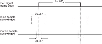
Figure 6.1: Timing limits recommended for synchronous signals in the AES11 standard.
The AES11 reference signal may either contain programme or not. If it does not contain programme it may be digital silence or simply the sync preamble with the rest of the frame inactive. Two grades of reference are specified: Grade 1, having a long-term frequency accuracy of 1 ppm (part per million), and Grade 2, having a long- term accuracy of 10 ppm. The Grade 2 signal conforms to the standard AES sample frequency recommendation for digital audio equipment (AES5-1984 2 ), and is intended for use within a single studio which has no immediate technical reason for greater accuracy, whereas Grade 1 is a tighter specification and is intended for the synchronization of complete studio centres (as well as single studios if required). Byte 4, bits 0 and 1 of the channel status data of the reference signal (see section 4.8) indicate the grade of reference in use (00 = default, 01 = Grade 1, 10 = Grade 2, 11 = reserved). It is also specified in this standard that the capture range of oscillators in devices designed to lock to external synchronizing signals should be 2 ppm for Grade 1 and 50 ppm for Grade 2. (Grade 1 reference equipment is only expected to lock to other Grade 1 references.)
Despite the introduction of this standard there are still many devices that do not use AES3-format DARS inputs, preferring to rely on BNC-connected word clock, video sync reference signals or other proprietary synchronization clocks.
6.2.2 Other Forms of External Sync Reference
Currently, digital audio recorders are provided with a wide range of sync inputs and most systems may be operated in the external or internal sync modes. In the internal sync mode a system is locked to its own crystal oscillator, which in professional equipment should be accurate within 10 parts per million (ppm) if it conforms to AES recommended practice, but which in consumer equipment may be much less accurate than this.
In the external sync mode the system should lock to one of its sync inputs, which may either be selectable using a switch, or be selected automatically based on an order of priority depending on the mode of operation (for this the user should refer to the operations manual of the device concerned ). Typical sync inputs are word clock (WCLK), which is normally a square-wave TTL-level signal (0-5V) at the sampling rate, usually available on a BNC-type connector; 'composite video', which is a video reference signal consisting of either normal picture information or just 'black and burst' (a video signal with a blacked-out picture); or a proprietary sync signal such as the optional Alesis sync connection or the LRCK in the Tascam interface (see section 4.12). WCLK may be 'daisy-chained' (looped through) between devices in cases where the AES/EBU interface is not available. Digidesign's ProTools system also uses a so-called 'Super Clock' signal at a multiple of 256 times the sampling rate for slaving devices together with low sampling jitter. This is a TTL level (0-5V) signal on a BNC connector. In all cases one machine or source must be considered to be the 'master', supplying the sync reference to the whole system, and the others as 'slaves'.
A 'sync' light is usually provided on the front panel of a device (or under a cover) to indicate good lock to an external or internal clock, and this may flash or go out if the system cannot lock to the clock concerned, perhaps because it has too much jitter, is at too low a level, conflicts with another clock, or because it is not at a sampling rate which can be accepted by the system.
Video sync (composite sync) is often used when a system is operated within a video environment, and where a digital recorder is to be referenced to the same sync reference as the video machines in a system. This is useful when synchronizing audio and video transports during recording and replay, using either a synchronizer or a video editor, when timecode is only used initially during the pre-roll, whereafter machines are released to their own video sync reference. It also allows for timecode to be recorded synchronously on the audio machine, since the timecode generator used to stripe the tape can also be locked to video syncs. The relationship between video frame rates and audio sampling frequencies is discussed further in section 6.6.1.
| | ||
| | ||
| | ||
EAN: 2147483647
Pages: 120
- ERP System Acquisition: A Process Model and Results From an Austrian Survey
- Enterprise Application Integration: New Solutions for a Solved Problem or a Challenging Research Field?
- Distributed Data Warehouse for Geo-spatial Services
- Relevance and Micro-Relevance for the Professional as Determinants of IT-Diffusion and IT-Use in Healthcare
- Development of Interactive Web Sites to Enhance Police/Community Relations