3.13 Parity
| | ||
| | ||
| | ||
3.13 Parity
The error-detection and error-correction processes are closely related and will be dealt with together here. The actual correction of an error is simplified tremendously by the adoption of binary. As there are only two symbols, 0 and 1, it is enough to know that a symbol is wrong, and the correct value is obvious. Figure 3.18 shows a minimal circuit required for correction once the bit in error has been identified. The XOR (exclusive-OR) gate shows up extensively in error correction and the figure also shows the truth table. One way of remembering the characteristics of this useful device is that there will be an output when the inputs are different. Inspection of the truth table will show that there is an even number of ones in each row (zero is an even number) and so the device could also be called an even parity gate. The XOR gate is also an adder in modulo-2.
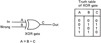
Figure 3.18: Once the position of the error is identified, the correction process in binary is easy.
Parity is a fundamental concept in error detection. In Figure 3.19, the example is given of a four-bit data word to be protected. If an extra bit is added to the word calculated in such a way that the total number of ones in the five-bit word is even, this property can be tested on receipt. The generation of the parity bit can be performed by a number of the ubiquitous XOR gates configured into what is known as a parity tree. In the figure, if a bit is corrupted, the received message will be seen no longer to have an even number of ones. If two bits are corrupted, the failure will be undetected. This example can be used to introduce much of the terminology of error correction. The extra bit added to the message carries no information of its own, since it is calculated from the other bits. It is therefore called a redundant bit.
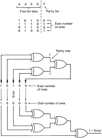
Figure 3.19: Parity checking adds up the number of ones in a word using, in this example, parity trees. One error bit and odd numbers of errors are detected . Even numbers of errors cannot be detected.
The addition of the redundant bit gives the message a special property, i.e. the number of ones is even. A message having some special property irrespective of the actual data content is called a codeword . All error correction relies on adding redundancy to real data to form codewords for transmission. If any corruption occurs, the intention is that the received message will not have the special property; in other words, if the received message is not a codeword there has definitely been an error. The receiver can check for the special property without any prior knowledge of the data content. Thus the same check can be made on all received data. If the received message is a codeword, there probably has not been an error. The word 'probably' must be used because the figure shows that two bits in error will cause the received message to be a codeword, which cannot be discerned from an error-free message.
If it is known that generally the only failure mechanism in the channel in question is loss of a single bit, it is assumed that receipt of a codeword means that there has been no error. If there is a probability of two error bits, which becomes very nearly the probability of failing to detect an error, since all odd numbers of errors will be detected, and a four-bit error is much less likely. It is paramount in all error-correction systems that the protection used should be appropriate for the probability of errors to be encountered . An inadequate error-correction system is actually worse than not having any correction. Error correction works by trading probabilities. Error-free performance with a certain error rate is achieved at the expense of performance at higher error rates. Figure 3.20 shows the effect of an error-correction system on the residual BER for a given raw BER. It will be seen that there is a characteristic knee in the graph. If the expected raw BER has been misjudged, the consequences can be disastrous. Another result demonstrated by the example is that we can only guarantee to detect the same number of bits in error as there are redundant bits.
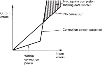
Figure 3.20: An error-correction system can only reduce errors at normal error rates at the expense of increasing errors at higher rates. It is most important to keep a system working to the left of the knee in the graph.
| | ||
| | ||
| | ||
EAN: 2147483647
Pages: 120
- An Emerging Strategy for E-Business IT Governance
- Measuring and Managing E-Business Initiatives Through the Balanced Scorecard
- A View on Knowledge Management: Utilizing a Balanced Scorecard Methodology for Analyzing Knowledge Metrics
- Measuring ROI in E-Commerce Applications: Analysis to Action
- Governance Structures for IT in the Health Care Industry