2.4 Types of Video Signal
| | ||
| | ||
| | ||
2.4 Types of Video Signal
Figure 2.1 shows some of the basic types of analog colour video; each of these types can, of course, exist in a variety of line standards. Since practical colour cameras generally have three separate sensors, one for each primary colour, an RGB system will exist at some stage in the internal workings of the camera, even if it does not emerge in that form. RGB consists of three parallel signals each having the same spectrum, and is used where the highest accuracy is needed, often for production of still pictures. Examples of this are paint systems and in computer-aided design (CAD) displays. RGB is seldom used for real-time video recording; there is no standard RGB recording format for post-production or broadcast. As the red, green and blue signals directly represent part of the image, this approach is known as component video.
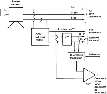
Figure 2.1: The major types of analog video. Red, green and blue signals emerge from the camera sensors, needing full bandwidth. If a luminance signal is obtained by a weighted sum of R, G and B , it will need full bandwidth, but the colour difference signals RY and BY need less bandwidth. Combining RY and BY in a subcarrier modulation scheme allows colour transmission in the same bandwidth as monochrome.
Some saving of bandwidth can be obtained by using colour difference working. The human eye relies on brightness to convey detail, and much less resolution is needed in the colour information. R, G and B are matrixed together to form a luminance (and monochrome compatible) signal Y , which has full bandwidth. The matrix also produces two colour difference signals, R Y and B Y , but these do not need the same bandwidth as Y ; one-half or one-quarter will do depending on the application. In casual parlance, colour difference formats are often called component formats to distinguish them from composite formats.
For colour television broadcast in a single channel, the PAL and NTSC systems interleave into the spectrum of a monochrome signal a subcarrier that carries two colour difference signals of restricted bandwidth. The subcarrier is intended to be invisible on the screen of a monochrome television set. A subcarrier-based colour system is generally referred to as composite video, and the modulated subcarrier is called chroma.
The majority of today's broadcast standards use 2:1 interlace in order to save bandwidth. Figure 2.2(a) shows that in such a system, there are an odd number of lines in a frame, and the frame is split into two fields. The first field begins with a whole line and ends with a half line, and the second field begins with a half line, which allows it to interleave spatially with the first field. Interlace may be viewed as a crude compression technique which was essentially rendered obsolete by the development of digital image compression techniques such as MPEG.
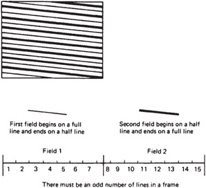
Figure 2.2a: 2:1 interlace.
The field rate is intended to determine the flicker frequency, whereas the frame rate determines the bandwidth needed, which is thus halved along with the information rate. Information theory tells us that halving the information rate must reduce quality, and so the saving in bandwidth is accompanied by a variety of effects that are actually compression artefacts . Figure 2.2(b) shows the spatial/temporal sampling points in a 2 :1 interlaced system. If an object has a sharp horizontal edge, it will be present in one field but not in the next . The refresh rate of the edge will be reduced to frame rate, and becomes visible as twitter. Whilst the vertical resolution of a test card is maintained with interlace, apart from the twitter noted, the ability of an interlaced standard to convey motion is halved. In the light of what is now known 1 , interlace causes degradation roughly proportional to bandwidth reduction, and so should not be considered for any future standards.
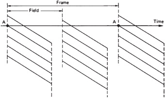
Figure 2.2b: In an interlaced system, a given point A is only refreshed at frame rate, causing twitter on fine vertical detail.
A wide variety of frame rates exist. Initially it was thought that a frame rate above the critical flicker frequency (CFF) of human vision at about 50 Hz would suffice, but this is only true for still pictures. When a moving object is portrayed, the eye tracks it and thus sees the background presented as a series of stills each in a different place. It is thus the prevention of background strobing that should be the criterion for frame rate. Needless to say the frame rate of film at 24 Hz is totally inadequate and the 50 and 60 Hz rates of television are suboptimal. Equipment running at 75 Hz or more gives obviously more fluid and realistic motion.
Originally film ran at 18 fps and to reduce flicker each frame was shown three times using a multi- blade shutter. During the development of 'talking pictures' it was found that the linear film speed at 18Hz provided insufficient audio bandwidth and the frame rate was increased to 24Hz to improve the sound quality. Thus the frame rate of movie film to this day is based on no considerations of human vision whatsoever. The adoption of digital film production techniques that simply retain this inadequate frame rate shows a lack of vision. Adigitized film frame is essentially the same as a progressively scanned television frame, but at 24 or 25Hz, a video monitor will be unacceptable because of flicker. This gave rise to the idea of a 'segmented frame' in which the simultaneously captured frame was displayed as fields containing alternately the odd and even lines. This allows digital film material to be viewed on television production equipment.
European television standards reflect the local AC power frequency and use 50 fields per second. American standards initially used 60 Hz field rate but on the introduction of colour the rate had to be reduced by 0.1% to 59.94 Hz to prevent chroma and sound interference.
Film cameras are flexible devices and where film is being shot for television purposes the film frame rate may be made 25 Hz or even 30 Hz so that two television fields may be created from each film frame in a telecine machine.
With the move towards high definition television, obviously more lines were required in the picture, with more bandwidth to allow more detail along the line. This, of course, only gives a better static resolution, whereas what was needed was better resolution in the case of motion. This requires an increase in frame rate, but none was forthcoming. High definition formats using large line counts but which retained interlace gave poor results because the higher static resolution made it more obvious how poor the resolution became in the presence of motion.
Those high definition standards using progressive scan gave better results, with 720 P easily outperforming interlaced formats. Digital broadcasting systems support the use of progressively scanned pictures. Video interfaces have to accept the shortcomings inherent in the signals they convey. Their job is simply to pass on the signals without any further degradation.
| | ||
| | ||
| | ||
EAN: 2147483647
Pages: 120