7.8 The SD Parallel Interface
| | ||
| | ||
| | ||
7.8 The SD Parallel Interface
Composite digital signals use the same electrical and mechanical interface as used for 4:2:2 component working 4 , 7 . This means that it is possible erroneously to plug a component signal into a composite machine. Whilst this cannot possibly work, no harm will be done because the signal levels and pinouts are the same.
A 25 pin D-type connector to ISO 2110-1989 is specified. Equipment always has female connectors, cables always have male connectors. Metal or metallized backshells are recommended with screened cables for optimum shielding. Equipment has been seen using ribbon cables and IDC (insulation displacement connectors), but is it not clear whether such cables would meet the newer more stringent EMC (electromagnetic compatibility) regulations. It should be borne in mind that the ninth and eighteenth harmonics of 13.5MHz are both emergency frequencies for aircraft radio.
Whilst equipment may produce or accept only eight-bit data, cables must contain conductors for all ten bits. Connector latching is by a pair of 4-40 (an American thread) screws, with suitable posts provided on the female connector. It is important that the screws are used as the multicore cable is quite stiff and can eventually unseat the plug if it is not secured. Some early equipment had slidelocks instead of screw pillars, but these proved to be too flimsy. During the changeover from slidelocks to 4-40 screws , some equipment was made with metric screw pillars and these will need to be changed to attach modern cables.
When unscrewing the locking screws from a D-connector it is advisable to check that the lock screw is actually unscrewing from the pillar. It is not unknown for the pillar to rotate instead. If this is not noticed, the pillar fixings may become detached inside the equipment, which will then have to be dismantled.
Each signal in the interface is carried by a balanced pair using ECL (emitter coupled logic) drive levels. The cable has a nominal impedance of 110 ohm and must be correctly terminated . ECL runs from a power supply of nominally -5.2 V and the logic states are -0.8 V for a 'high' and -1.85 V for a 'low'. ECL is primarily a current driven system, and the signal amplitude is quite low compared with other logic families as well as being negative valued.
Figure 7.15 shows the pinouts used. Although it is not obvious from the figure, the numbering of the D-connector is such that signal pairs are on physically opposite pins. Originally most equipment used eight-bit data and ten-bit working was viewed as an option; this was reflected in the wording of the first standards. However, in order to reflect the increasing quantity of ten-bit equipment now in use, the wording of later standards has subtly changed to describe a ten-bit system in which only eight bits may be used.
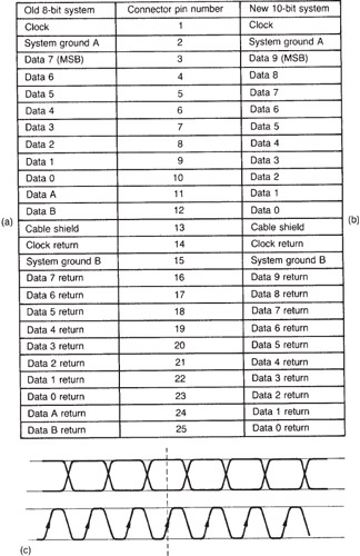
Figure 7.15: The parallel interface was originally specified as in (a) with eight bits expandable to ten. Later documents specify a ten-bit system (b) in which the bottom two bits may be unused. Clock timing at (c) is arranged so that a clock transition occurs between data transitions to allow maximum settling time.
In the old specification shown in Figure 7.15(a), there are eight signal pairs and two optional pairs, so that extension to a ten-bit word can be accommodated. The optional signals were used to add bits at the least significant end of the word. Adding bits in this way extends resolution rather than increasing the magnitude. It will be seen from the figure that the optional bits are called Data-1 and Data-2 where the-1 and -2 refer to the powers of two represented, i.e. 2 -1 and 2 -2 . The eight-bit word describes 256 levels and ends in a radix point. The extra bits below the radix point represent the half and quarter quantizing intervals. In this way a degree of compatibility exists between tenand eight-bit systems, as the correct magnitude will always be obtained when changing word length, and all that is lost is a degree of resolution in shortening the word length when the bits below the radix point are lost. The same numbering scheme can be used for both word lengths; the longer word length simply has a radix point and an extra digit in any number base. Converting to the eight-bit equivalent can then be simply a matter of deleting the extra digit and retaining the integer part.
However, the later specification shown in (b) renumbers the bits from 0 to 9 and assumes a system with 1024 levels. Thus all standard levels defined in the old 8 + 2-bit documents have to be multiplied by four to convert them to the levels in the new ten-bit documents. Thus a level of 16 decimal or 10 hex in the eight-bit system becomes 64 decimal or 40 hex in the ten-bit system. Figure 7.16 shows that 8 + 2 schemes may use hexa-decimal numbering in the XYZ or XYLo format where two hex digits X and Y represent the most significant eight bits and the remaining two bits are represented by the Z or Lo symbol. Ten-bit schemes are numbered with three hex digits PQR where P only has two meaningful bits.
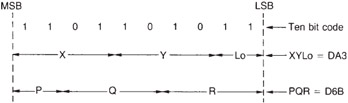
Figure 7.16: As there are two ways to parse ten bits into hexadecimal, there are two numbering schemes in use. In the XYLo system the parsing begins from the MSB down and the Lo parameter is expressed in quarters . In the PQR system the parsing starts from the LSB and so the P parameter has a maximum value of 3.
A separate clock signal pair and a number of grounding and shielding pins complete the connection. Figure 7.15 also shows the relationship between the clock and the data. A positive-going clock edge is used to sample the signal lines after the level has settled between transitions. In component, the clock will be line-locked 27 MHz or 36 MHz irrespective of the line standard, whereas in composite digital the clock will be four times the frequency of the PAL or NTSC subcarrier .
The parallel interface is suitable for distances of up to 50 metres (27 MHz) or 40 metres (36 MHz). Beyond this distance equalization is likely to be necessary and skew or differential delay between signals may become a problem. Equalization of such a large number of signals is not economically viable .
The parallel interface sends active line blocks sandwiched between SAV and EAV TRS codes. The remainder of the blanking periods will contain words whose value alternates between the luma and colour difference blanking codes, unless ancillary data is being sent.
| | ||
| | ||
| | ||
EAN: 2147483647
Pages: 120