Growth Problems and Hidden Reserves
|
| < Day Day Up > |
|
When overclocking is discussed, it usually relates to the processor, and often to the memory modules. Most individuals define overclocking as a forced increase of the clock frequency. As a result of such operations, computer performance improves considerably. If you purchase a system equipped with Intel Pentium 4, operating at a frequency of 1.6 GHz, and with DDR266 memory modules (DDR SDRAM operating at 266 MHz), you could use straightforward manipulations to make it operate as Intel Pentium 4 with a frequency of 2.4 GHz equipped with DDR333 memory modules. Detailed instructions on performing these procedures will be covered later in this book. Here, a general understanding will be given of the CPU clock frequency specified in the product names of various processors (such as Intel).
CPU clock frequency, usually expressed in gigahertz, determines the time interval, also known as clock, during which the processor executes a specific number of instructions. If a processor has a clock frequency of 1 GHz, then 1 clock equals 1 nanosecond (nsec). If a processor has a clock frequency of 2 GHz, 1 clock is half the length of that from the previous processor; therefore, it equals 0.5 nsec. Consequently, the processor is capable of executing the same number of instructions twice as fast (if both processors execute the same number of instructions per clock). Based on these facts, the performance of the second processor is twice that of the first processor. In practice, however, this conclusion is not quite right.
At this point, the term processor performance should be clarified. From the end user's point of view, processor performance is the time required to execute a specific set of commands that make up the program code. The smaller this time interval, the greater the performance of the processor installed in a specific system. This means that performance can be considered the number of commands executed per clock multiplied by the CPU clock frequency:
Performance = (Commands per clock) × (Clock frequency)
The number of commands executed per clock depends both on the program being executed and on the processor architecture (i.e., which set of commands can be processed and how this job is done). At the processor level, each command is converted into a set of several machine instructions or elementary commands. The efficiency of this transform depends both on the processor architecture and on the code optimization for specific processor architecture. Besides this, depending on the processor architecture, elementary commands can be executed in parallel.
These considerations make it clear that it would be incorrect to compare the performance of processors that have different architecture if that comparison is based only on their clock frequencies. Some applications might run more efficiently on AMD processors; other ones may perform better on Intel processors with the same clock frequency.
However, within one processor family (i.e., processors that are based on the same architecture but have different clock frequencies), such a comparison would be correct.
Thus, to increase the processor performance, it is expedient to raise its clock frequency. To be more precise, the improvement is made to the semiconductor core, the basis of this key computer component.
Each processor is intended to operate at the specified clock frequency. If the manufacturer declares that a processor is designed to run at 1,600 MHz, this is an objective reality, rather than simple declaration. Intel Pentium 4 processors of 1,600 MHz and 2 GHz are manufactured using the same technology, under the same conditions, and at the same technological line. However, various circumstances can cause deviations from specified parameters, which result in slightly different characteristics of the final products. To detect such deviations and their consequences, manufacturers perform technological control and testing of their products. Naturally, it is impossible to test each processor separately, especially taking into account the scale of production. The common practice is to perform selective testing of each party of the final product. During this testing, the manufacturer determines the general ability of the processors to run at a specific clock frequency. Then, the entire group of processors is marked according to that frequency. A specific processor purchased by a customer may not have undergone the procedure of selective testing; thus it may be capable of supporting a higher clock frequency than the declared one. Finally, each manufacturer provides some "reliability reserve" that accounts for static dispersion of parameters, because it is impossible to guarantee reproduction of manufacturing processes. As a result, most processors can run at increased clock frequencies (i.e., they can be successfully overclocked).
However, as processor manufacturing technologies become more advanced, the static parameter dispersion narrows. This enables manufacturers to supply more powerful processors and gradually decrease their "reliability reserve." As a result, low-end models are more promising to overclockers than high-end ones (Fig. 3.1).
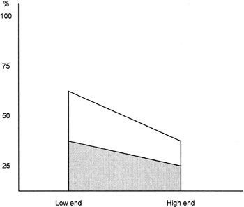
Figure 3.1: Performance reserve for low-end and high-end processor in various overclocking modes
Fig. 3.1 shows performance reserve for low-end and high-end processors in different overclocking modes. The dark area corresponds to moderate overclocking modes; the light area shows extreme modes, which sometimes can be implemented only under specific conditions.
Which effects and physical processes prevent unlimited growth of the internal frequencies of the semiconductor core?
Recall that contemporary processors installed in modern PCs comprise millions of elementary units made of transistors manufactured using Complementary Metal-Oxide Semiconductor (CMOS) technology. Furthermore, a semiconductor core, such as Northwood, created using 130-nanometer technology and serving as the basis for Intel Pentium 4 processors, comprises 55 million of transistors. Its successor, the Prescott core, manufactured according to the 90-nanometer technology, comprises more transistors. The size of each sophisticated unit is smaller than the size of a typical flu virus. These millions of transistors are connected to one another in specific ways, are concentrated in an extremely small area, and often operate at frequencies that already exceed 10 GHz. All these elements can produce negative effects on one another. This can be illustrated by an example of two adjacent conductors that connect elements of the processor core.
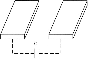
Figure 3.2: Two adjacent conductors that connect elements in the processor core
These conductors are characterized by mutual capacitance. This capacitance depends on the distance between them and on the area of the facing sides. The value of this capacitance is calculated according to a well-known formula C = k × S/d, where C is the capacitance, S is the area, d is the distance, and k is permittivity coefficient, whose physical meaning will be considered later.
For a direct current, this configuration is a reliable dielectric; at high frequencies, mutual capacitance generates uncontrolled currents because the capacitor formed by the two conductors has a certain conductivity. Although conductors are small, the distance between them also is very small. The high values of the frequencies and the high number of conductors (there are millions of them) means their influence on the frequency properties of the internal core structures is not negligible. This is especially true because each capacitor, besides capacitance, is characterized by resistance and inductance. This means that the equivalent circuit of the configuration formed by two conductors represents a set of capacitors, resistors, and inductors. It has the properties of the integrating circuit with multiple resonance frequencies. Furthermore, there is mutual influence among several conductors. This statement is illustrated by Fig. 3.3, which presents the configuration that would be formed by three conductors.
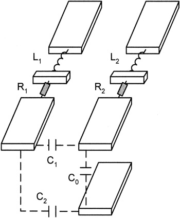
Figure 3.3: Three neighboring conductors that connect core elements
Undisputedly, the frequency properties of such a configuration are considerably more complex than those of the diagram formed by two conductors. Both active (resistors) and reactive (capacitors and inductors) components of the impedance are distributed along the entire length of the conductors. This significantly complicates the behavior of such systems at high frequencies. The situation is worse because conductors do not operate in vacuum. On the contrary, they are surrounded by a medium with specific dielectric properties, which influences the values of mutual capacitance. Furthermore, materials used in chip manufacturing have permittivity that exceeds 1; therefore, the values of mutual capacity are higher than those produced by the cases just considered. An approximation that illustrates this situation is in Fig. 3.4.
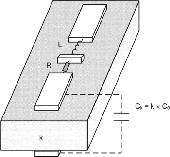
Figure 3.4: Two conductors, with consideration for dielectric influence
Based on this illustration, it is clear why designers try to use materials with smaller values of permittivity (k) to insulate semiconductor chips.
The frequency characteristics in all these cases depend on a range of factors: the size of conductors, their mutual position, the chemical composition of conductors and of surrounding dielectrics, microscopic defects, etc. Any variation in these parameters changes the frequency characteristics. This explains why the "reliability reserve" is mandatory for sophisticated components operating at high frequencies.
Besides conductor topology, it is necessary to consider the influence of transistors, whose structure and physical nature are more complicated than those of individual conductors. Besides controlling currents, transistors themselves are powerful sources of electromagnetic radiation. Transistors also influence adjacent elements and are exposed to similar effects. The p-n-junctions present in their structure can perform detection of undesirable parasitic currents, their amplification, and their transmission. It is hard to imagine the intensity of the electromagnetic field within a processor chip; the elements are packed so densely that they are characterized by alternating fields of high intensity. These fields form a complicated structure that changes depending on the different operating frequencies of internal processor structures, forming maximums and minimums in different areas of the chip.
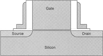
Figure 3.5: Transistor structure
The general pattern is even more complicated, especially because at current transistor sizes, the influence of quantum effects is considerable and gradually increases. These effects, despite advances in transistor architecture, increase uncontrolled currents. Their total flow represents a combination of currents generated by insulation defects, those generated by leaks of a different nature via capacitors, and even the ones caused by the tunnel effect. This part of the uncontrolled current is large, and it tends to grow with an increase in clock frequency. This also requires manufacturers to provide reliability reserve in their products.
To compensate for negative effects and ensure stable CPU operation at higher frequencies, manufacturers have to increase core voltage. Compare the core voltages for low-end and high-end processors. For high-end models, the core supply voltages are always higher, no matter which architecture and manufacturing technology is used.
If you increase the clock frequency above the standard level and need to ensure reliable operation of the processor (as well as of the RAM modules, graphics processor of the video adapter, and video memory), you also need to increase the voltage. For moderate overclocking, this increase must not exceed the maximum values recommended by the manufacturer. These parameters are provided in technical documents known as datasheets. Usually, the limiting values established by processor manufacturers are approximately 10 percent above the standard value. Provided that normal operating conditions are ensured, which primarily relates to the temperature modes, such an increase doesn't result in a significant decrease of the processor's lifetime due to the rapid degradation of semiconductors.
Unfortunately, increasing the power-supply voltage and clock frequency also increases the temperature, which can be evaluated by the following formula:
P ≈ C × V2 × F
Here, P is the heat generated by the CPU, in watts; C is the correction factor that accounts for the mutual capacitance of the processor-core components, depending on its architecture; V is the power-supply voltage; and F is the clock frequency in gigahertz.
This formula can be expressed as follows:
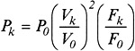
The variables with the index of k designate overclocked parameters; the variables with the index of 0 represent standard values.
Table 3.1 presents an evaluation of the expected heat generation for an Intel Pentium 4 processor with a standard operating frequency of 2 GHz in different overclocking modes, with P0 = 52.4 W and V0 = 1.50 V.
| Fk(GHz) | 2.1 | 2.2 | 2.4 | 2.6 |
| Vk(V) | 1.50 | 1.50 | 1.55 | 1.60 |
| Pk(W) | 55.0 | 57.6 | 67.1 | 77.5 |
If a processor's clock frequency is decreased until it is below its standard value, the core voltage also can be decreased appropriately without disrupting overall system stability. According to the previous formula, this decreases the heat emitted by the processor. Such operations are usually performed automatically by combinations of specific hardware and software. Normally, they are intended to reduce power consumption and are typical for mobile computers. However, the same approach is also applicable to desktop computers.
Note that in recent years, the generated heat has increased even for standard operating modes. This happened despite PC designers' constant efforts to improve CPU internal structures and decrease the core voltage. Decreasing the core voltage became possible with the reduction of the transistor sizes, and, consequently, a decrease in the sizes of their gates. The gate controls the source-drain current. The thinner the gate, the lower the voltage required to maintain field intensity.
A reduction in the channel length is accompanied by a reduction of losses. The newest research aimed at improving transistor topology also helps improve parameters.
Thus, technological advances and improvement of processor architecture ensure an increase of CPU clock frequencies (Fig. 3.6).
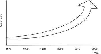
Figure 3.6: Exponential growth of processor performance (based on IDF data)
Unfortunately, this performance growth also has a dark side: increased heat emission. The area of the processor chip hardly changes; therefore, this growth in heat emission results from increased energy density.
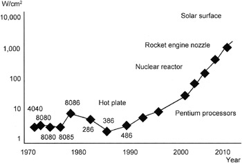
Figure 3.7: Growth of the energy density inside a processor chip, compared to other densities (based on IDF data)
Under conditions of inadequate cooling, the high heat emission overheats the processor's internal structures, which negatively affects its reliability and speeds up the processes of semiconductor decay.
Semiconductors are sensitive to heating. The average energy of atom oscillations grows with the temperature. As a result, the number of broken links in the grid of the silicon crystal grows, and new pairs of electrons and holes appear. When the temperature limit is reached, semiconductor properties change. For example, conductivity of semiconductors and dielectrics grows as the temperature rises. As a result, the system begins to malfunction, and failures become persistent. To avoid these negative effects, it is necessary to use adequate cooling. Currently, no high-performance processor can operate without a high-quality cooler equipped with a massive heatsink and a powerful fan. It would be logical to suppose that by taking special steps to ensure CPU cooling, stable operation of chips designed for room temperature can be achieved. Note that such chips are usually overclocked to frequencies that considerably exceed the standard values. In particular, such measures (which are not actively promoted) were used at an Intel Developer Forum (IDF) session during a demonstration of standard processors in extreme overclocking modes.
Among the facilities that ensure extreme overclocking, a special place is held by the cooling facilities that reduce the CPU temperature below the ambient temperature. Specially designed freezers (or freezing chambers) are used for this purpose. This idea isn't new or revolutionary; most corporations specializing in high-end servers demonstrated temperature overclocking at least at an experimental level. Such manufacturers include Sun Microsystems, IBM, and Compaq. In 1991, Intel and NCR started "temperature overclocking under manufacturing conditions," a project known as Cheetah. The portfolio of patents registered within the range of this project later became the property of the six founders of KryoTech, who at that time were working as researchers for NCR. Later, these developments enabled KryoTech professionals to create a range of facilities that ensure efficient cooling of overclocked CPUs, at the expense of placing them, with motherboards, into freezing chambers.
Cryogenic methods of cooling overclocked components also can be considered variants of such solutions. Some details of such experiments that relate to extreme CPU overclocking will be presented later in this chapter. However, before proceeding to extreme overclocking, consider some aspects of traditional moderate overclocking modes.
|
| < Day Day Up > |
|
EAN: 2147483647
Pages: 111