The Basics
| I first learned to draw sequence diagrams in 1978. James Grenning, a longtime friend and associate, showed them to me while we were working on a project that involved complex communication protocols between computers connected by modems. What I am going to show you here is very close to the simple notation he taught me then, and it should suffice for the vast majority of sequence diagrams that you will need to draw. Objects, Lifelines, Messages, and Other Odds and EndsFigure 18-1 shows a typical sequence diagram. The objects and classes involved in the collaboration are shown at the top. Objects have underlined names; classes do not. The stick figure (actor) at left represents an anonymous object. It is the source and sink of all the messages entering and leaving the collaboration. Not all sequence diagrams have such an anonymous actor, but many do. Figure 18-1. Typical sequence diagram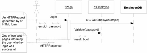 The dashed lines hanging down from the objects and the actor are called lifelines. A message being sent from one object to another is shown as an arrow between the two lifelines. Each message is labeled with its name. Arguments appear either in the parentheses that follow the name or next to data tokens (the little arrows with the circles on the end). Time is in the vertical dimension, so the lower a message appears, the later it is sent. The skinny little rectangle on the lifeline of the Page object is called an activation. Activations are optional; most diagrams don't need them. Activations represent the time that a function executes. In this case, it shows how long the Login function runs. The two messages leaving the activation to the right were sent by the Login method. The unlabeled dashed arrow shows the Login function returning to the actor and passing back a return value. Note the use of the e variable in the GetEmployee message. This signifies the value returned by GetEmployee. Note also that the Employee object is named e. You guessed it: They're one and the same. The value that GetEmployee returns is a reference to the Employee object. Finally, note that because EmployeeDB is a class, its name is not underlined. This can only mean that GetEmployee is a static method. Thus, we'd expect EmployeeDB to be coded as in Listing 18-1. Listing 18-1. EmployeeDB.cs
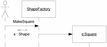
Creation and DestructionWe can show the creation of an object on a sequence diagram by using the convention shown in Figure 18-2. An unlabeled message terminates on the object to be created, not on its lifeline. We would expect ShapeFactory to be implemented as shown in Figure 18-2. Figure 18-2. Creating an object Listing 18-2. ShapeFactory.cs
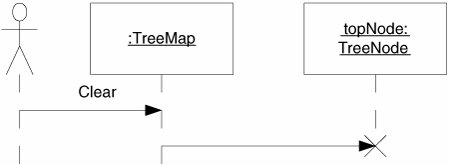
In C#, we don't explicitly destroy objects. The garbage collector does all the explicit destruction for us. However, there are times when we want to make it clear that we are done with an object and that, as far as we are concerned, the garbage collector can have it. Figure 18-3 shows how we denote this in UML. The lifeline of the object to be released comes to a premature end at a large X. The message arrow terminating on the X represents the act of releasing the object to the garbage collector. Figure 18-3. Releasing an object to the garbage collector Listing 18-3 shows the implementation we might expect from this diagram. Note that the Clear method sets the topNode variable to null. Since it is the only object that holds a reference to that treeNode instance, the treeMap will be released to the garbage collector. Listing 18-3. treeMap.cs
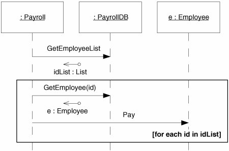
Simple LoopsYou can draw a simple loop in a UML diagram by drawing a box around the messages that repeat. The loop condition is enclosed in brackets and is placed somewhere in the box, usually at the lower right. See Figure 18-4. Figure 18-4. A simple loop This is a useful notational convention. However, it is not wise to try to capture algorithms in sequence diagrams. Sequence diagrams should be used to expose the connections between objects, not the nitty-gritty details of an algorithm. Cases and ScenariosDon't draw sequence diagrams like Figure 18-5, with lots of objects and scores of messages. Nobody can read them. Nobody will read them. They're a huge waste of time. Rather, learn how to draw a few smaller sequence diagrams that capture the essence of what you are trying to do. Each sequence diagram should fit on a single page, with plenty of room left for explanatory text. You should not have to shrink the icons down to tiny sizes to get them to fit on the page. Figure 18-5. An overly complex sequence diagram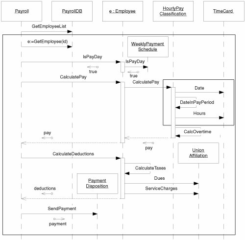 Also, don't draw dozens or hundreds of sequence diagrams. If you have too many, they won't be read. Find out what's common about all the scenarios and focus on that. In the world of UML diagrams, commonalities are much more important than differences. Use your diagrams to show common themes and common practices. Don't use them to document every little detail. If you really need to draw a sequence diagram to describe the way messages flow, do them succinctly and sparingly. Draw as few of them as possible. First, ask yourself whether the sequence diagram is even necessary. Code is often more communicative and economical. Listing 18-4, for example, shows what the code for the Payroll class might look like. This code is very expressive and stands on its own. We don't need the sequence diagram to understand it, so there's no need to draw the sequence diagram. When code can stand on its own, diagrams are redundant and wasteful. Listing 18-4. Payroll.cs
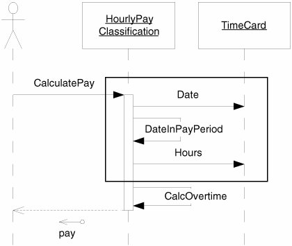
Can code really be used to describe part of a system? In fact, this should be a goal of the developers and designers. The team should strive to create code that is expressive and readable. The more the code can describe itself, the fewer diagrams you will need, and the better off the whole project will be. Second, if you feel that a sequence diagram is necessary, ask yourself whether there is a way to split it up into a small group of scenarios. For example, we could break the large sequence diagram in Figure 18-5 into several much smaller sequence diagrams that would be much easier to read. Consider how much easier the small scenario in Figure 18-6 is to understand. Third, think about what you are trying to depict. Are you trying to show the details of a low-level operation, as in Figure 18-6, which shows how to calculate hourly pay? Or are you trying to show a high-level view of the overall flow of the system, as in Figure 18-7? In general, high-level diagrams are more useful than low-level ones. High-level diagrams help the reader tie the system together mentally. They expose commonalities more than differences. Figure 18-6. One small scenario Figure 18-7. A high-level view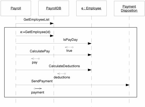 |
EAN: 2147483647
Pages: 272