802.11a
|
| < Day Day Up > |
|
When the IEEE ratified the 802.11a and 802.11b wireless networking communications standards in 1999, its goal was to create a standards-based technology that could span multiple physical encoding types, frequencies and applications in the same way the 802.3 Ethernet standard has been successfully applied to 10 Mbps, 100 Mbps and 1000 Gbps technology, over fiber and various kinds of copper. However, unlike its more popular sibling, 802.11b, it took a while to commercialize 802.11a. (For the reasons why, see the "Why 'b' Before 'a'" text box.) But that is old news; 802.11a has overcome its slow start and is now a viable player in the wireless networking marketplace.
The 802.11a standard, which supports data rates of up to 54 Mbps, is the Fast Ethernet analog to the 11 Mbps 802.11b. Like Ethernet and Fast Ethernet, 802.11b and 802.11a use an identical MAC (Media Access Control). However, while Fast Ethernet uses the same Physical Layer encoding scheme as Ethernet (only faster), 802.11a uses an entirely different encoding scheme than 802.11b. That encoding scheme is OFDM.
This specification also delivers other major changes. 802.11a specifies operation in the 5 GHz Unlicensed National Information Infrastructure (U-NII) bands-5.15-5.25 GHz, 5.25-5.35 GHz, and 5.725-5.825 GHz. It offers data rates that range from 6 to 54 Mbps. (Devices utilizing 802.1 la are required to support speeds of 6, 12, and 24 Mbps; most now include 48, 36, 18 and 9 Mbps support as well). This standard also offers higher capacity and less radio frequency interference with other types of devices than its slower sibling. Within this spectrum, there are twelve 20 MHz channels (802.11a uses eight of these channels) and each band offers different output power limits.
| Note | The U-NII bands have several advantages over ISM, one of the most notable being their ability to support 10 Mbps and higher data transfer rates. The U-NII bands also are dedicated solely to high data rate communications. |
Because of its operation in the larger and currently less crowded U-NII bands, 802.11a may offer less potential for RF interference than the other PHY standards (i.e. 802.11b and 802.11g) that utilize the smaller and more congested ISM band. Also, since it offers high data rate capabilities, 802.11a easily can support voice and multimedia applications and densely populated user environments.
Transmit Frequencies
The IEEE 802.11a Task Group elected to use a version of OFDM proposed by NTT and Lucent, which is known as "Coded Orthogonal Frequency Division Multiplexing," although this book and others simply refer to the modulation technique as OFDM. This OFDM version sends a stream of data symbols in a massively parallel fashion over multiple sub-carriers, which essentially are small slices of RF spectrum within a designated channel within a designated carrier frequency band.
The IEEE 802.1 la standard specifies an OFDM Physical Layer that splits an information signal across 52 separate sub-carriers to provide transmission of data at a rate of 6, 9, 12, 18, 24, 36, 48, or 54 Mbps, with the 6, 12, and 24 Mbps data rate capability being mandatory. Four of the 52 sub-carriers are pilot sub-carriers that the system uses as a reference to disregard frequency or phase shifts of the signal during transmission. A pseudo binary sequence is sent through the pilot sub-channels to prevent the generation of spectral lines. The remaining 48 sub-carriers provide separate wireless pathways for sending the information in a parallel fashion. The resulting sub-carrier frequency spacing is 0.3125 MHz (for a 20 MHz-wide channel with 64 possible sub-carrier frequency slots).
In the U.S., the FCC allocated 300 MHz of spectrum for unlicensed operation in the 5 GHz block, 200 MHz of which is at 5.15 MHz to 5.35 MHz, with the other 100 MHz at 5.725 MHz to 5.825 MHz. The spectrum is split into three working "domains." The first 100 MHz in the lower section is restricted to a maximum power output of 50 mW (milliwatts). The second 100 MHz has a more generous 250 mW power budget, while the top 100 MHz is delegated for outdoor applications, with a maximum of one Watt power output. (See Fig. 6.2.)
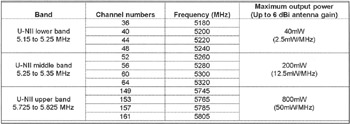
Figure 6.2: 802.11a's OFDM operating bands, channels, transmit frequencies and maximum output power. The low and middle bands are intended for in-building applications, and the high band for outdoor use (e.g., building-to-building).
| Note | Unlike 802.11a, 802.11b cards can radiate as much as one Watt of power, outdoor or indoor (at least in the U.S.), although most modern radio cards radiate only a fraction-30 mW-of the maximum available power, due to the need for battery conservation and heat dissipation. |
As previously stated, the 802.11a standard operates in the 5 GHz frequency range, with a total bandwidth available for IEEE 802.11a applications of 300 MHz. That is almost four times that of the ISM band, which offers only 83 MHz of spectrum in the 2.4 GHz range for 802.11b devices.
As shown in Fig. 6.2, there are twelve 20 MHz channels, and each band has different output power limits. In the U.S., the Code of Federal Regulations, Title 47, Section 15.407, regulates these frequencies.
| Note | The 802.11a standard requires receivers to have a minimum sensitivity ranging from -82 to -65 dBm (decibels referenced to 1 milliwatt), depending on the chosen data rate. Because of the relatively low power limits in the lower frequency bands, WLAN designers should carefully consider range requirements of the application before choosing a particular band. For a fuller understanding of RF power values, see Appendix II. |
The 802.1 la standard gains some of its performance from the higher frequencies at which it operates. The laws of information theory tie frequency, radiated power, and distance together in an inverse relationship. Thus, moving up from 2.4 GHz to the 5 GHz spectrum allows for shorter practical distances, given the same radiated power and encoding scheme. In addition, the encoding mechanism used to convert data into analog radio waves can encode one or more bits per radio cycle (more commonly referred to as "Hertz"). By rotating and manipulating the radio signal, vendors can encode more information in the same time slice.
To ensure that the remote host can decode these more complex radio signals, you must use more power at the source to compensate for signal distortion and fade. The 802.11a technology overcomes some of the distance loss by increasing the equivalent (or effective) isotropic (or isotropically) radiated power (EIRP) to the maximum allowable value of 50 mW.
| Note | According to Newton's Telecom Dictionary, the EIRP is the product of the power supplied to the transmitting antenna and the antenna gain in a given direction relative to an isotropic antenna radiator. EIRP may be expressed in Watts or dB (above one Watt). |
Physical Signals
The 802.1 la designers hoped that OFDM could give 802.11a systems 802.11b-like transmission distances. And at lower speeds it can. Furthermore, the variation of OFDM that 802.11a uses was developed specifically for indoor wireless use and thus offers performance much superior to that of spread spectrum solutions.
802.11a's OFDM techniques work by breaking one high-speed data carrier into several lower-speed sub-carriers, which are then transmitted in parallel to each other. Each 20 MHz wide high-speed carrier is broken up into 52 sub-channels, each approximately 300 KHz wide. Coded OFDM uses 48 of these sub-channels for data, while the remaining four are used for error correction. 802.11a's encoding scheme and error correction technique also serve to aid 802.11a in its efforts to deliver higher data rates and a high degree of multipath reflection recovery.
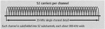
Figure 6.3: 802.11a sub-channels.
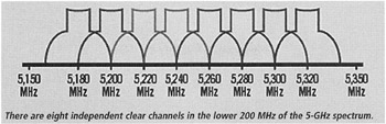
Figure 6.4: 802.11a independent clear channels.
At the low end of the speed gradient, binary phase shift keying (BPSK) is used to encode 125 Kbps of data per channel, resulting in a 6000 Kbps, or 6 Mbps, data rate. But if you use quadrature phase shift keying (QPSK), it is possible to double the amount of data encoded to 250 Kbps per channel, yielding a 12 Mbps data rate. And by using 16-level quadrature amplitude modulation (QAM) encoding 4 bits per hertz, you can achieve a data rate of 24 Mbps. (See Fig. 6.5.) The 802.11a standard specifies that all 802.11a-compliant products must support those three basic data rates. But the standard also allows vendors to extend the modulation scheme beyond 24 Mbps. However, remember that the more bits per cycle (hertz) that are encoded, the more susceptible the signal will be to interference and fading, and ultimately, the shorter the range, unless power output is increased.
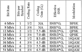
Figure 6.5: Parameters for 802.11a transmission rates.
802.11a's top data rate of 54 Mbps is achieved by using 64 QAM, which yields 8 bits per cycle or 10 bits per cycle, for a total of up to 1.125 Mbps per 300 KHz channel. (With 48 channels, that results in a 54 Mbps data rate.)
As you might expect, the higher speeds work only under the best of circumstances and only over very short distances, with the exact distance being fairly unpredictable because so many factors can influence it.
The symbol rate refers to the rate of transmission of a symbol, or set of bits. The delay spread is the variation in timing between receipt of the signals associated with a given symbol. This delay spread is caused by multipath fading. It follows that the symbol rate must be slowed down enough that each symbol transmission is longer than the delay spread, which is sensitive to the degree to which the transmitter and receiver have clear line-of-sight.
Since the data rates are so high, the modulation techniques so sophisticated and sensitive, and the quality of the airwaves so uncertain and tenuous, 802.1 la specifications include forward error correction (FEC). Through the embedding of some redundant data in the payload, the receiving device typically can detect, isolate, diagnose and correct errors in transmission.
While this approach inherently adds some overhead to the transmission and further reduces throughput, it largely obviates the need for bandwidth-intensive retransmissions. Although it also necessitates the embedding of some additional intelligence in the receiving device, the costs of doing so are fairly modest in contemporary terms. On balance, this approach is much more efficient and cost-effective than its alternatives.
At the MAC sublayer, 802.11a makes use of the Carrier Sense Multiple Access with Collision Avoidance (CSMA/CA) protocol, which requires that each attached device broadcast a request to send (RTS) frame before transmitting. If the RTS frame gets through, the destination device responds with a clear to send (CTS) frame. All other devices on the network honor this reservation, and the transmission ensues. While RTS serves to make CSMA/CA more reliable, it does so at a cost. The RTS/CTS frames consume bandwidth, which means that this approach is somewhat overhead intensive and, therefore, affects total throughput. Also, the additional programmed logic makes CSMA/CA somewhat more expensive.
CSMA/CA is used in 802.11a systems because the allotted RF spectrum is so limited between the shared access point and the client workstations that an unacceptable level of collisions would otherwise result. So while there are some drawbacks to using CSMA/CA, on balance, it is more cost-effective than its alternatives.
PHY and MAC
The primary purpose of the OFDM PHY is to transmit media access control (MAC) protocol data units (MPDUs) as directed by the 802.11 MAC sublayer. The OFDM PHY is divided into two sublayers: the physical layer convergence protocol (PLCP) and the physical medium dependent (PMD).
The MAC sublayer communicates with the PLCP via specific primitives through a PHY service access point. When the MAC sublayer instructs, the PLCP prepares MPDUs for transmission. The PLCP also delivers incoming frames from the wireless medium to the MAC sublayer. The PLCP sublayer minimizes the dependence of the MAC sublayer on the PMD sublayer by mapping MPDUs into a frame format suitable for transmission by the PMD.
Under the direction of the PLCP, the PMD provides actual transmission and reception of PHY entities between two stations through the wireless medium. To provide this service, the PMD interfaces directly with the air medium and provides modulation and demodulation of the frame transmissions. The PLCP and PMD communicate using service primitives to govern the transmission and reception functions.
Frame formats and protocol. The PLCP preamble field (see Fig. 6.6) is present for the receiver to acquire an incoming OFDM signal and synchronize the demodulator. The preamble consists of 12 symbols. Ten of the symbols are short for establishing automatic gain control (AGC) and the coarse frequency estimate of the carrier signal. The receiver uses the long symbols for fine-tuning. With this preamble, it takes 16 microseconds to train the receiver after first receiving the frame.
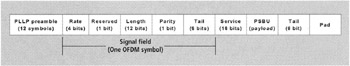
Figure 6.6: This graphic illustrates the frame format for an 802.11a frame.
The signal field consists of 24 bits, defining data rate and frame length. The 802.11a version of OFDM uses a combination of BPSK, QPSK, and QAM, depending on the chosen data rate (see Fig. 6.5). The length field identifies the number of octets in the frame. The PLCP preamble and signal field is convolutionally encoded and sent at 6 Mbps using BPSK, no matter what data rate the signal field indicates.
The convolutional encoding rate depends on the chosen data rate (see Fig 6.7). The parity field is one bit based on positive (even) parity, and the tail field consists of six bits (all zeros) appended to the symbol to bring the convolutional encoder to zero state.
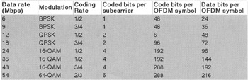
Figure 6.7: Modulation techniques of OFDM as used in 802.11a.
| Note | Convolutional encoding refers to the convolutional code that is generated by inputting a bit of data, giving the commutator a complete revolution, and then repeating the process for successive input bits to produce a convolutionally encoded output. The convolutional code is produced by a convolutional coder, which is a coder with memory. The convolutional coder accepts k binary symbols at its input and produces n binary symbols at its output, where the n output are affected by v+k input symbols. Memory is incorporated because v>0. Code rate R=k/n. Typical values: k, n: 1 - 8; v: 2-60; R: 0.25-0.75. |
The service field consists of 16 bits, with the first six bits as zeros to synchronize the descrambler in the receiver, and the remaining nine bits (all 0s) are reserved for future use. The PLCP service data unit (PSDU) is the payload from the MAC sublayer being sent. The pad field contains at least six bits, but it is actually the number of bits that make the data field a multiple of the number of coded bits in an OFDM symbol (48, 96, 192, or 288). A data scrambler using a 127-bit sequence generator scrambles all bits in the data field to randomize the bit patterns in order to avoid long streams of 1s and 0s.
With 802.11a OFDM modulation, the binary serial signal is divided into groups (symbols) of one, two, four, or six bits, depending on the data rate chosen, and converted into complex numbers representing applicable constellation points. If a data rate of 24 Mbps is chosen, for example, then the PLCP maps the data bits to a 16-QAM constellation (see Fig. 6.8). The constellation is gray-coded.
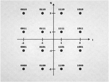
Figure 6.8: Constellation map for the 16-QAM 802.11a modulation.
After mapping, the PLCP normalizes the complex numbers to achieve the same average power for all mappings. The PLCP assigns each symbol, having a duration of four microseconds, to a particular sub-carrier. An inverse Fast Fourier Transform (FFT) combines the sub-carriers before transmission.
As with other 802.11-based PHYs, the PLCP implements a clear channel assessment protocol by reporting a medium busy or clear signal to the MAC sublayer via a primitive through the service access point. The MAC sublayer uses this information to determine whether to issue instructions to actually transmit an MDSU.
802.11a's version of OFDM with its high degree of spectral efficiency and resiliency to interference and multipath distortion, and existing inclusions in the leading higher rate WLAN standards, provides a strong base for the development of newer broadband wireless networks.
802.11a in Europe
For a time after its introduction, 802.11a was either limited or forbidden by most European nations, since many reserved the 5 GHz band for military or security use. When WLAN vendors like Siemens, Philips Electronics, and Ericsson complained to the ETSI about the lack of spectrum for their 802.11a equipment, the North Atlantic Treaty Organization (NATO) interceded, pointing out to the ETSI that it uses parts of the 5 GHZ band for radar and satellites. A long battle ensued. The outcome was HiperLAN/2, which the ETSI created as a standard method for wireless LANs to use the 5 GHz spectrum in Europe.
However, HiperLAN/2 didn't catch on in the marketplace. Nonetheless, it did serve one purpose-to clear the path for 802.1 la to gain a foothold Europe. Since HiperLAN/2 devices have not found a market, at the behest of some 802.11a supporters, ETSI has since modified its position. The ensuing modifications allows equipment that's not based on the HiperLAN/2 standard to be used in the 5 GHz range (with some exceptions) as long as the products:
-
Follow the IEEE 802.1 la specifications.
-
Have the ability to "sense" when radar or other types of broadcasts enter the spectrum and have the intelligence to avoid them. This technique is known as Dynamic Frequency Selection (DFS).
-
Use Transmit Power Control (TPC) to reduce a radio signal's power depending on how close a device with an 802.11a card is to the access point.
Chipsets used in 802.11a products destined for Europe now include both DFS and TPC. In the U.S., negotiations are underway between the FCC and the Department of Defense to accommodate similar measures.
While 802.11a products that meet the ETSI requirements can be sold in nine European countries-Austria, Belgium, Denmark, Finland, France, Greece, Ireland, Norway and Portugal-these products still face a few more local regulatory hurdles. After meeting the ETSI certification demands, 802.11a equipment makers must incorporate the specific requirements of regulatory agencies within each European country in which they want to sell their 802.11a equipment. These countries often have requirements other than those imposed by the ETSI.
At this writing, most of the European countries have officially allowed 802.1 la broadcasts in the 5.15 GHz to 5.35 GHz range, and the 5.47 GHz to 5.725 GHz range. A few countries, however, have carved out different areas within those two ranges in which Wi-Fi can operate, and made some channels within the spectrum off-limits.
Due to local regulatory requirements, as of mid-2002, 802.11a products were only available in France, the UK, the Netherlands, Belgium, Denmark, and Sweden. And, to give you an idea of how muddled this subject is in Europe, in mid-2002, Proxim (a prominent Wi-Fi vendor) traveled to Spain to demonstrate its new 802.11a equipment, and the government refused its request to use the appropriate spectrum.
The Future
What about HiperLan/2? Well, it is still clinging to life, but just barely. As you shall learn, other 802.11 standards are addressing the 5 GHz, 802.11a/ HiperLAN/2 issues, e.g. 802.11d, h and j. As for 802.11a, it is expected that it will find worldwide acceptance, although some industry pundits opine that 802.11g will quash 802.11a's growth in Europe and elsewhere.
ETSI's HiperLAN: The European Telecommunications Standards Institute (ETSI) is one of the world's most respected standards bodies, publishing many telecommunications standards. One of those standards is HiperLAN, which grew out of efforts to develop a wireless version of the wired ATM networking technology. The original HiperLAN standard was approved by ETSI in February 2000. That standard operates at rates up to 20 Mbps.
Like Wi-Fi, HiperLAN is a family of standards: HiperLAN, HiperLAN/2, HiperAccess (also known as HiperLAN/3), and HiperLINK (or HiperLAN/4). Note, however, that the latter two standards aren't applicable to local area networks.
Also like Wi-Fi, HiperLAN and HiperLAN/2 specifications define the Data Link Layer and the Physical Layer, along with the Data Link Layer's two sublayers: the Logical Link Control (LLC) and the Medium Access Control (MAC).
While the original HiperLAN standard and its successor, HiperLAN/2, are still on the books; they seem to be archaic. Furthermore, although there are supporters who market this technology for local area networking, it looks like HiperLAN/2 may merge with the IEEE's 802.11a.
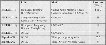
Figure 6.9: Although HiperLan/2 has lain dormant since its ratification, its predecessor has had some success outside the U.S.
Japan's MMAC: In Japan, the Multimedia Mobile Access Communication (MMAC) Systems Promotion Council group is developing specifications for advanced types of wireless systems. However the IEEE is developing additional standards, under the guidance of Task Group 802.11j, to meet Japanese regulatory guidelines, and therefore MMAC, like the HiperLAN standards, is unlikely to meet the market momentum of Wi-Fi. (See "802.11j" in this chapter.)
|
| < Day Day Up > |
|
EAN: 2147483647
Pages: 273