Virtual Links
|
|
OSPF allows the creation of a virtual link that can be used to repair a partitioned backbone, or to connect a discontiguous area to the backbone. Though virtual links are generally considered evidence of poor network design, the prepared JNCIP exam candidate will be able to configure and test them as required.
The following configuration task is designed to illustrate the configuration and operational aspects of a virtual link:
-
Ensure that r7 can ping destinations in area 10 when r5 loses backbone connectivity (as shown in Figure 3.6).
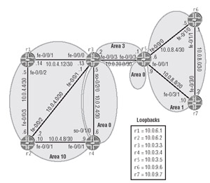
Figure 3.6: OSPF virtual links
Figure 3.6 provides a modified OSPF topology showing that r5 has lost backbone connectivity due to the deactivation of its at-0/1/0 and as1 interfaces. This topology also shows the addition of a new area, area 3, which has already been configured between r5 and r3. r5's area 3 definition is shown in the following:
[edit] lab@r5# show protocols ospf area 3 interface fe-0/0/3.0;
Because summary LSAs should be exchanged only over the backbone area, the loss of backbone connectivity will result in connectivity problems between areas 10 and 1, as shown in the following screen dumps. A key point is that even though r5 is receiving a summary LSA for the 10.0.4/22 area 10 aggregate from r3, the router refuses to install the route. This is because r6 expects to receive such summaries via area 0, not area 3:
lab@r5> show ospf database netsummary extensive advertising-router 10.0.3.3 area 3 OSPF link state database, area 0.0.0.3 Type ID Adv Rtr Seq Age Opt Cksum Len Summary 10.0.2.4 10.0.3.3 0x80000005 137 0x2 0x1922 28 mask 255.255.255.252 TOS 0x0, metric 1 Aging timer 00:57:43 Installed 00:02:16 ago, expires in 00:57:43, sent 00:02:17 ago Summary 10.0.3.3 10.0.3.3 0x80000005 137 0x2 0x2019 28 mask 255.255.255.255 TOS 0x0, metric 0
Despite the presence of area 0 and area 10 summary LSAs, r5 has not installed any of the routes because the summaries were not received over the backbone area:
lab@r5> show route 10.0.4/22 lab@r5> lab@r5> show route 10.0.3.3 lab@r5>
To restore connectivity over the partitioned backbone, you will need to establish a virtual link that transits area 3 and interconnects r5 to the backbone-attached r3. Virtual links are always configured under area 0 and can be configured only on an ABR. By definition, any router with a virtual link becomes a backbone router, and one end of the virtual link must terminate at a router that is actually backbone attached.
The following commands configure a virtual link on r5 and display the resulting virtual link configuration:
[edit protocols ospf area 0] lab@r5# set virtual-link neighbor-id 10.0.3.3 transit-area 3 [edit protocols ospf area 0.0.0.0] lab@r5# show | match virtual virtual-link neighbor-id 10.0.3.3 transit-area 0.0.0.3;
With the definition of the virtual link, you have effectively re-attached r5 to area 0 by instructing it to establish a virtual adjacency to r3 by transiting area 3. It should be noted that the virtual link endpoints are defined based on the remote router's RID, not its physical address, and that the virtual link can only cross one transit area. Once committed, we confirm that r5 is now trying to establish an adjacency with r3:
lab@r5> show ospf interface Interface State Area DR ID BDR ID Nbrs lo0.0 DR 0.0.0.0 10.0.3.5 0.0.0.0 0 vl-10.0.3.3 PtToPt 0.0.0.0 0.0.0.0 0.0.0.0 0 fe-0/0/0.0 BDR 0.0.0.1 10.0.9.6 10.0.3.5 1 fe-0/0/1.0 BDR 0.0.0.1 10.0.9.7 10.0.3.5 1 fe-0/0/3.0 DR 0.0.0.3 10.0.3.5 10.0.3.3 1
The presence of a virtual link 'interface' confirms that r5 is trying to communicate with the backbone-attached router identified as 10.0.3.3. The lack of a neighbor on the virtual link is due to the fact that r3's virtual link back to r5 has not yet been configured.
The following command is now entered (and committed) on r3 to complete the definition of the virtual link:
[edit protocols ospf area 0.0.0.0] lab@r3# set virtual-link neighbor-id 10.0.3.5 transit-area 3
We now recheck the status of the virtual link from the perspective of r6:
lab@r5> show ospf neighbor Address Interface State ID Pri Dead 10.0.20.2 vl-10.0.3.3 Full 10.0.3.3 0 31 10.0.8.5 fe-0/0/0.0 Full 10.0.9.6 128 32 10.0.8.10 fe-0/0/1.0 Full 10.0.9.7 128 35 10.0.20.2 fe-0/0/3.0 Full 10.0.3.3 128 39
The full adjacency status is a very good sign. The next command confirms the presence of the aggregate route for area 10 on r5:
lab@r5> show route 10.0.4/22 inet.0: 21 destinations, 21 routes (21 active, 0 holddown, 0 hidden) + = Active Route, - = Last Active, * = Both 10.0.4.0/22 *[OSPF/10] 00:00:43, metric 3 > to 10.0.20.2 via fe-0/0/3.0
The aggregate route's presence indicates that the configuration of the virtual link was successful. The final check is to confirm that r7 can now reach area 10 destinations:
[edit] lab@r7# run traceroute 10.0.6.2 traceroute to 10.0.6.2 (10.0.6.2), 30 hops max, 40 byte packets 1 10.0.8.9 (10.0.8.9) 0.366 ms 0.294 ms 0.239 ms 2 10.0.20.2 (10.0.20.2) 0.322 ms 0.284 ms 0.256 ms 3 10.0.6.2 (10.0.6.2) 0.211 ms 0.244 ms 0.189 ms
After confirming the operation of the virtual link backbone, you should restore backbone connectivity on r5 by reactivating its at-0/2/1.35 and as1 interfaces. After r5 reestablishes its area 0 adjacencies, the virtual link and area 3 definitions should be removed from r3 and r5. The results of this traceroute confirm that r5's area 0 interfaces have been correctly reactivated:
[edit] lab@r7# run traceroute 10.0.6.2 traceroute to 10.0.6.2 (10.0.6.2), 30 hops max, 40 byte packets 1 10.0.8.9 (10.0.8.9) 0.347 ms 0.247 ms 0.217 ms 2 10.0.2.2 (10.0.2.2) 0.870 ms 0.657 ms 0.876 ms 3 10.0.6.2 (10.0.6.2) 0.500 ms 0.675 ms 0.368 ms
|
|
EAN: 2147483647
Pages: 132