Section 9.4. UWB Multiple Hop Ad Hoc Networks
|
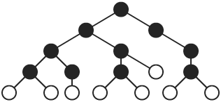
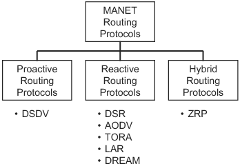
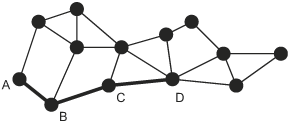
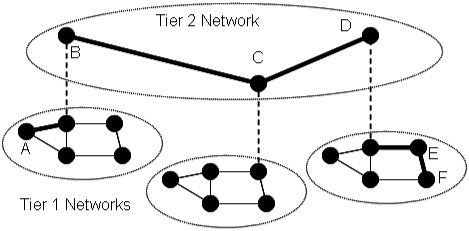
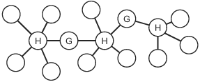
9.4. UWB Multiple Hop Ad Hoc NetworksA network is required to enable data communications beyond point-to-point link communication. Some networks, called infrastructure-based networks, rely on preexisting infrastructure to enable multiple hop communication. Other networks, called ad hoc networks, are self-organizing, require no infrastructure, and can be set up "on the fly." Under many circumstances, mobile nodes in an ad hoc network do not have direct physical links to all other nodes; that is, not all nodes are within radio range of all other nodes in the network. A multiple hop ad hoc network enables nodes without direct physical links to communicate through one or more intermediate nodes. In addition, a multiple hop ad hoc network may extend radio coverage and allow efficient radio resource sharing. We can categorize multiple hop ad hoc network topologies into one of two types, flat topologies and hierarchical topologies. A flat topology is a strictly peer-to-peer, fully distributed network where each node can serve as both an ordinary node (a source or a destination) and a router. A node acting as a router serves as an intermediate node on the path between source and destination nodes that are not directly connected at the physical layer. Figure 9.8 illustrates a flat network topology. In the figure, a path is shown from source node A to destination node D using node B and node C as intermediate routers. Figure 9.8. A Flat Multiple Hop Ad Hoc Network. A hierarchical network topology consists of one or more localized networks or clusters of nodes called tier 1 networks and a single backbone network called the tier 2 network, as illustrated in Figure 9.9. All nodes in a cluster can be directly connected or, as shown in the figure, multiple hop routing may be needed to reach all nodes in a cluster. Within a cluster, that is, within a tier 1 network, ordinary nodes are controlled by a cluster head that participates in a multiple hop tier 2 network. As an example, a path from node A to node F is shown in the figure. The example path goes from source node A to node B within a single cluster. The path goes from node B to node C and on to node D in the backbone network. From node D, the path goes to node E and then to destination node F within a single cluster. A fully distributed flat topology offers great flexibility and fairness among all nodes, whereas a hierarchical topology with a central control node in each cluster is often more efficient and more scalable. In a flat topology, each node acts on its own, but all the nodes in the network must participate in distributed management functions such as routing. In a hierarchical topology, a node in each cluster can be "elected" as a central control node by other nearby nodes. A network with a hierarchical topology can use a central control node to manage each cluster, and to communicate with one or more other nodes in the tier 1 network. Bluetooth, which has been standardized as IEEE 802.15.1, uses a hierarchical topology, with a star topology used in tier 1 clusters [2]. The IEEE 802.15.3 high rate wireless personal area network standard uses a hybrid topology in clusters [15]. The control is centrally managed, but data communications are distributed. UWB is being considered as a PHY layer option for IEEE 802.15.3 and, thus, the same hybrid topology will be used with a UWB physical layer. Figure 9.9. A Hierarchical Multiple Hop Ad Hoc Network. The following sections discuss hierarchical topologies and flat topologies. Routing algorithms for each of these two types of topologies are briefly introduced. 9.4.1. Hierarchical Network TopologiesFor a UWB multiple hop network, a hierarchical topology may be an appropriate choice because a large distributed topology introduces significant synchronization and communication overhead. The hierarchical topology allows a hybrid architecture. Nodes are self-organized into clusters and a cluster head is "elected" for each cluster. The cluster head can coordinate spreading code assignments, power control, and other localized functions within its cluster. Cluster heads also participate in a longer range, multiple hop, distributed backbone network. A scatternet in Bluetooth, as shown in Figure 9.10, is an example of a hierarchical topology [17]. In a Bluetooth scatternet, nodes are organized into clusters, called piconets in Bluetooth terminology. Adopting a hierarchical topology, some nodes become cluster heads or gateway nodes, while other nodes remain as ordinary nodes that rely on cluster heads and gateway nodes for communication. Cluster heads are sometimes called "masters" and ordinary nodes are sometimes called "slaves." Throughout this section, we will use the terms interchangeably. A cluster head, labeled as "H" in Figure 9.10, controls other nodes in the same cluster and relays traffic within the cluster. A gateway node, labeled as "G" in Figure 9.10, relays control information and directs data traffic from one cluster to another. Thus, multiple hop communication is achieved by connecting master nodes and gateway nodes. Even though cluster heads and gateway nodes carry a higher computational and communication burden than other nodes and may become bottlenecks, routing information propagated in the network can be reduced, especially for large-scale ad hoc networks. This is because the routing function must consider only routing to clusters and not to each individual node, as would be the case with a flat topology. Figure 9.10. Example Scatternet with Cluster Heads (H) and Gateway Nodes (G). Initially, all nodes in the network are isolated, that is, a node is not aware of the existence of any of the other nodes. A scatternet formation algorithm can be used to connect all or most of the isolated nodes together into a multiple hop network. Many scatternet formation algorithms have been proposed. Existing algorithms can be classified into three categories: those that use a "super-master" node, those that construct a scatternet to fit a basic topology model, and those that use basic node clustering techniques. The first category includes algorithms that rely on a single elected "super-master" node to interconnect the rest of the nodes. The super-master node must acquire information from all other nodes through a distributed procedure. A two-stage distributed clustering algorithm is proposed by Ramachandran, et al. [18]. The first stage uses a randomized distributed algorithm to select master-designates and slave-designates. During this stage, all N nodes in the network conduct T rounds of Bernoulli trials with a probability of p, where p The second stage is a deterministic algorithm to select masters and a super-master node. First, all master-designates start to solicit information about slave nodes. If a slave-designate responds to the inquiry, it becomes a slave in the cluster as long as the maximum cluster size, S, is not exceeded. If a master-designate collects S slaves in its cluster or experiences a time-out after it has collected at least one node in its cluster, it declares itself to be a master. If a master-designate fails to collect any responses before it times out, it becomes a slave-designate and starts to look for inquiries from other master-designates. If a master or a master-designate collects up to a threshold of k responses from other clusters, it becomes the super-master. After a node declares itself as a super-master, it solicits information from all other clusters. After obtaining the required information, the super-master partitions the network into exactly k clusters, with k 1 clusters having S slaves and one cluster of size N mod (S + 1). Then, the super-master selects appropriate nodes in the clusters to serve as gateway nodes. As simple as this algorithm is, it requires that each node has prior information about the total number of nodes, N. In addition, this algorithm needs some predefined parameters, namely S and k, whose optimal values may not be easy to determine prior to the deployment of the network. The Bluetooth Topology Construction Protocol (BTCP) is an asynchronous, fully distributed scatternet formation algorithm developed by Salonidis, et al. [19]. BTCP provides a good example of an approach that may be useful for a UWB network. BTCP has three phases: the leader election phase, the role determination phase, and the connection establishment phase. In the leader election phase, an asynchronous distributed election of a coordinator node is performed. At the end of the first phase, the leader node has a global view of the network. Thus, at the second phase, the leader node can assign roles to the remaining nodes. Some of the nodes are picked as master nodes and some are assigned to be gateway nodes. The rest of the nodes remain as ordinary nodes. During the last phase, all designated master nodes are required to connect to gateway nodes and ordinary nodes. This scheme does not require any a priori information about the network. However, it only works for a number of nodes less than or equal to 36, due to the desired properties of the resulting network [19]. Because the two-stage distributed clustering algorithm [18] and BTCP [19] depend on a single node to determine the scatternet topology and notify other nodes, this special node needs to acquire information from the other N 1 nodes in the network. Thus, both algorithms have complexity O(N) at the leader election phase. Algorithms in the second category construct a scatternet based on a specific topology model, such as a spanning tree topology. Because a spanning tree topology is simple to realize and relatively efficient for packet routing, many scatternet formation algorithms are based on tree structures. Figure 9.11 shows a spanning tree topology with dark nodes as parent nodes. Figure 9.11. Spanning Tree Topology. A spanning tree topology tends to select the least possible number of links to form a connected scatternet. Note that the minimum number of connections is a property of a spanning tree [20]. Moreover, a spanning tree is easy to maintain because of its hierarchical structure. For example, each node maintains routing tables only to its children and grandchildren nodes. When the destination of a packet is in a node's routing table, the node will transmit the packet to the corresponding children. Otherwise, the packet is forwarded upward to the node's parent. However, a spanning tree topology has some deficiencies [21]. First, it lacks robustness and may result in a single point of failure. After a parent node fails, all the children and grandchildren nodes are separated from the rest of the network. Second, routing in a tree topology is less efficient compared to routing in several other topologies, such as a mesh topology, because data can only move through a tree in the upward and downward directions. Therefore, the throughput or delay for a spanning tree routing algorithm can sometimes be much worse than for routing algorithms based on other topologies. Third, because all the routing paths go through parent nodes, these nodes, especially the ones higher in the hierarchy, may become heavily loaded, thus becoming performance bottlenecks in the network. "Bluetree" is a simple spanning tree-based algorithm developed by Zaruba, et al. [21]. The assumptions for this algorithm are that there is a predesignated "blueroot" node in the network, that each node knows the identity of its neighbors, and that each node knows whether or not it is already part of a piconet. After nodes in the network power on, the "blueroot" node starts paging its neighbors one by one. If a node is paged but has not yet joined a piconet, it becomes a slave of the paging node. When a node has been assigned as a slave in a piconet, it initiates the one-by-one paging of all of its neighbors. This procedure is recursively repeated until all nodes are assigned to a piconet. A second algorithm proposed by Zaruba, et al., in the same work relaxes these assumptions. Instead of having one "blueroot" node for the whole network, any node that has the highest identification (ID) number among its neighbors can elect itself as a root and initiate the "Bluetree" procedure. The network is then spanned by connecting together disjoint, but adjacent, trees. Algorithms in the third category do not assume any particular model for the network topology. Instead, they construct "flatter" architectures using basic clustering schemes. "Bluenet" and "BlueStars" are examples of this category of algorithm. The "Bluenet" algorithm, developed by Wang, et al., has three phases [3]. In the first phase, isolated piconets are formed by clustering. After this phase, some separated nodes may be left out of the network. In the second phase, these separated nodes try to associate with at least one piconet. When the second phase completes, all nodes should be associated with at least one piconet. During the third phase, piconets are connected to form a scatternet. However, "Bluenet" does not guarantee the connectivity of the resulting scatternet. One of the major contributions of Wang, et al., is that they define two metrics for evaluating the performance of scatternets, the average shortest path (ASP) and the maximum traffic flow (MTF) [3]. The "BlueStars" protocol also proceeds in three phases: the topology discovery phase, the piconet formation phase, and the scatternet formation phase [17]. During the first phase, each node discovers its neighbor nodes and makes them aware of its presence. The second phase takes care of piconet formation. Based on a precomputed weight, each node decides whether it is going to be a master or a slave. One master and one or more other nodes establish communication links to form a "BlueStar." During the final phase, each master uses information gathered from neighboring nodes during the first phase to select gateway nodes. The selection of gateway nodes is performed so that the resulting scatternet is connected. The completed scatternet is a connected mesh with multiple paths between any pair of nodes, which guarantees robustness. 9.4.2. Flat Network TopologiesThe majority of research on routing in multiple hop ad hoc networks assumes a flat topology and a fully distributed architecture. A UWB ad hoc network is sometimes called a UWB mesh network. Even though mesh networking is a relatively new area of research, significant research and development efforts have been dedicated to it. Both IEEE 802.15 and IEEE 802.11 standard groups have formed subgroups to investigate standards for wireless mesh networks. Because each node in a mesh network can act as a router, and the routing operation is completely decentralized, mesh networks offer great flexibility and can ensure fairness among nodes. In a mesh network, nodes cooperate to forward packets for each other to reach destinations that are not directly within the source node's transmission range. Thus, ad hoc routing algorithms are needed to ensure connectivity in such networks, especially where nodes can move, as is the case in mobile ad hoc networks (MANETs). Routing ProtocolsFigure 9.12 specifies three categories of MANET routing protocols: proactive protocols, reactive protocols, and hybrid protocols. Proactive protocols are typically link-state (table-driven) protocols that maintain up-to-date routing information regardless of whether there is any request for a particular route. The Destination Sequenced Distance Vector (DSDV) protocol is a typical proactive routing protocol [22]. Figure 9.12. Basic Taxonomy for MANET Routing Protocols. Reactive protocols are called source initiated on-demand routing protocols since route discovery is invoked only when a source node has a packet to send that needs a route. Examples of reactive routing protocols include Dynamic Source Routing (DSR) [23], Ad hoc On-Demand Distance Vector Routing (AODV) [24], Temporally Ordered Routing Algorithm (TORA) [25], Location Aided Routing (LAR) [26], and Distance Routing Effect Algorithm for Mobility (DREAM) [27]. Hybrid routing protocols combine features of reactive and proactive protocols. The Zone Routing Protocol (ZRP) is such a hybrid protocol [28]. Some examples of MANET routing protocols are described in the following sections. Destination Sequenced Distance Vector (DSDV) ProtocolDSDV is a table-driven proactive routing protocol based on the classical Bellman-Ford routing algorithm [22]. One of the distinct contributions of DSDV is that it avoids the routing loops that are often generated by the basic Bellman-Ford algorithm. Each node in the network maintains a routing table that records all reachable destinations and the number of routing hops. The method for building these routing tables is the same as the scheme used in the Bellman-Ford algorithm [13]. Bellman-Ford is a distributed algorithm, which means that each node executes the algorithm simultaneously with every other node. The Bellman-Ford algorithm does not assume that a node knows the details of the network topology. Instead, it assumes that a node initially knows only the length (or cost) of its outgoing links and the identity of every destination that is directly connected. Using information supplied by its neighbors, every node computes the shortest distance (or lowest cost) to every other node in the network. And, every node shares information about its shortest (or least cost) paths with its neighbors. Because the source node updates a sequence number every time it sends out a route request, intermediate nodes can distinguish out-of-date, or "stale," route update messages from new update messages. By associating a sequence number with the route request, DSDV avoids the introduction of any loops. Dynamic Source Routing (DSR)As the name suggests, DSR is based on the source node that determines and specifies a route to the destination [23]. The DSR protocol consists of two phases: route discovery and route maintenance. Because on-demand routing protocols create routes only when desired by the source node, they all typically have these two phases. The route discovery phase is initiated only when a source node needs to send one or more packets to a destination to which the source does not have an up-to-date route. When a route has been established, it is maintained by a route maintenance procedure until the route expires. If a node has a packet to send, it first checks its own routing cache to see whether there is an unexpired route to the destination. If no existing route is found, the source node initiates a route discovery procedure by sending a Route Request message that contains source and destination addresses and a unique request identifier. Each node receiving the Route Request message checks whether it knows an unexpired route to the destination. If no route is found, the node appends its own address to the Route Request packet and rebroadcasts the packet to its neighbors. If an intermediate node knows an unexpired route to the destination or the node is the destination node, a Route Reply message is generated. If symmetric links are assumed, the node can simply reverse the route in the route record of the Route Request message to send a reply back to the source. If symmetric links cannot be assumed, a node generating a Route Reply message may need to initiate its own route discovery procedure. In a mobile environment, links may fail due to fading, interference, or node movements. Therefore, route maintenance is a crucial procedure in routing protocols for MANETs. In the DSR protocol, route maintenance is accomplished through the use of acknowledgments and Route Error messages. Acknowledgments are used to verify the correct operation of the links in a path from source to destination. A Route Error message is sent to the original sender of the data packet when a link fails. Upon receiving a Route Error message, the sender removes the failed link from its route cache. This may trigger a new route discovery procedure. As an on-demand routing protocol, DSR is very flexible. However, DSR introduces large routing overhead and does not scale well for use in large networks, because all the routing information has to be carried in packet headers. Ad Hoc On-Demand Distance Vector Routing (AODV)AODV is, in essence, a combination of DSR and DSDV [24]. However, AODV makes improvements over both protocols. In a manner similar to DSR, AODV also employs two phases: route discovery and route reply. A node initiates a route discovery by broadcasting a Route Request (RREQ) message when it has packets for a destination node for which it has no valid route. Any node that receives the RREQ message updates its next hop table entry with respect to the preceding node in the path back to the source, thereby establishing a reverse path back to the initiator of the RREQ message. If a node does not have a route to the destination node, it rebroadcasts the RREQ message to its neighbors. If a node knows an unexpired route to the destination or the node is the destination node, a Route Reply (RREP) message is generated and sent by unicast back to the source. Upon receiving the RREP message, each node along the route back to the source updates its next hop table entry with respect to the neighboring node along the path to the destination node. Because the RREP message is forwarded along the reverse path established by the RREQ message, AODV requires symmetric links. Unlike DSR, AODV does not include route information in every data or control packet header, which reduces overhead. AODV also has less routing overhead than DSDV because it can minimize the number of required broadcasts by creating routes in an on-demand manner. Temporally Ordered Routing Algorithm (TORA)TORA is a highly adaptive reactive routing protocol [25]. It guarantees loop-free routes and can typically provide multiple routes for any pair of source and destination nodes. It is also distributed, in the sense that nodes need only maintain information about their adjacent neighbors. Another distinctive feature of TORA is that the protocol's reaction to link failures typically involves only a localized "single pass" of the distributed algorithm to correct for a failed link. TORA has three phases: route creation, route maintenance, and route erasure. During the route creation and route maintenance phases, a query and reply process is used to build a directed acyclic graph (DAG) rooted at the destination node. At every node, a separate copy of TORA is run for every destination. For a given destination node, each participating node is assigned a "height." No two nodes may have the same "height," i.e., the set of "heights" is totally ordered. Each link is assigned a direction, upstream or downstream, based on the relative "height" metric of the neighboring nodes. Timing is an important factor in TORA because the "height" metric is based on the logical time of a link failure. Thus, TORA assumes that all nodes in the network are synchronized (at least coarsely). Data packets can be routed from nodes with higher "height" to nodes with lower "height," just like water can only flow from a higher altitude to a lower altitude. TORA maintains a set of totally ordered "heights" at all times. When a node needs a route to a given destination, it broadcasts a Query message containing the address of the destination for which it requires a route. The Query message travels through the network until it reaches the destination or an intermediate node that has a route to the destination node. This node then broadcasts an Update message listing its height with respect to the destination. As the Update message propagates through the network, each node updates its height to a value greater than the height of the neighbor from which it receives the Update. This results in a series of directed links from the node that originated the Query to the destination node. Thus, loop-free multipath routing to the destination can be created. If a node discovers a destination to be unreachable, it sets a local maximum value of height for that destination. In case the node cannot find any neighbor having finite height with respect to this destination, it attempts to find a new route. If a link failure partitions the network, the node broadcasts a Clear message that resets all routing states and removes invalid routes from the network. Zone Routing Protocol (ZRP)ZRP is a hybrid proactive and reactive routing protocol [28]. A routing zone is defined for every node in the network. The zone radius is a predetermined parameter that defines the zone in terms of the minimum number of hop counts (number of links that must be traversed) from the center node. All neighbor nodes within the radius of the zone are considered to be nodes in the routing zone. If the minimum hop count of a node from the center node is exactly the same as the zone radius, this node is called a border node. Each node in the network proactively maintains its own routing zone, using a proactive routing protocol, such as DSDV. Therefore, each node in the zone knows how to reach every other node in the same zone at any time. If a node wants to send a packet, it first checks whether the destination node is in its own zone. If the destination is in the same zone, it can send the packet directly to the destination because proactive routing protocols always maintain up-to-date routing information. If the destination is not in the same zone, the sender initiates a reactive routing protocol, such as DSR. To reduce the number of route search messages that are broadcast, a node only needs to transmit Route Query packets to a zone's border nodes. This operation is called "bordercasting." When the border nodes receive the query packet, they repeat the same procedure in their own zone until the destination node is reached. The zone radius is a parameter that can be tuned to fit different network requirements. ZRP becomes a purely proactive routing protocol if the zone radius is set to be equal to or larger than the network diameter (the maximum number of hops between any two nodes in the network) or if the zone radius is set to one. Location-Aided Routing (LAR)Because UWB can provide precise ranging and cooperative nodes can determine location through time-of-arrival (TOA) or time-difference-of-arrival (TDOA) techniques, LAR schemes may be of particular interest for UWB networks. LAR schemes were introduced to reduce the scope of route request flooding. The basic ideas behind different versions of LAR schemes are similar. If a source node knows approximately where the destination node lies, it can restrict the propagation of route request messages only in that direction, significantly reducing the overhead for route discovery. LAR defines two zones: the expected zone and the request zone [26]. The expected zone is defined as the region that is expected to hold the current location of the destination node. The request zone specifies a region based on the location of the source node and the expected zone. Only intermediate nodes located in the request zone can forward route request messages. First, the source node determines an expected zone based on some prior knowledge of the location and estimated speed of the destination node. Then, the source node calculates a request zone that contains the expected zone and its own location. The request zone is explicitly specified in the route request. Only nodes within the request zone forward the route request message. If a route discovery operation fails to find a route due to stale location information or incorrect estimates of node speed, a larger request zone is used for the next route discovery operation. This new request zone can include the entire network, which results in flooding a route request to the entire network. Distance Routing Effect Algorithm for Mobility (DREAM)DREAM is another routing algorithm that uses location information [27]. DREAM also assumes that nodes know their physical location and can estimate their speeds. However, unlike LAR that uses control packets for route discovery, DREAM uses the flooding of data packets as a routing mechanism. Moreover, DREAM takes the distance effect into consideration when updating routes. Based on the observation that far away nodes seem to move at a lower angular speed as compared to nearby nodes, DREAM uses a time-to-live (TTL) field in location updates to control how far the information can propagate. The TTL value is calculated by estimating the distance between the source and the destination nodes in terms of the number of hops. Nodes periodically update their location information. Because of the TTL value, nearby nodes are updated more frequently than more distant nodes. This can reduce the overhead for routing updates. Because both the DREAM and LAR algorithms use location information, they can limit the scope of route request flood and potentially reduce the overhead associated with route discovery. However, both algorithms require that nodes know their physical location and have information about their speed, so these two routing protocols may not work well for a network where nodes have limited capabilities or a heterogeneous network with some nodes not having knowledge of their location or speed. It is worth noting that none of the routing protocols is the best under all conditions. Different routing protocols may be used for different network conditions, including different topology characteristics, different assumptions about mobility, and different traffic loads and communication patterns. |
|
EAN: 2147483647
Pages: 110
 1, for each trial. Nodes with exactly one successful trial become master-designates and other nodes become slave-designates.