The (Internet Draft) Standard MPLS MIBs
| The two MIBs described in the IETF drafts "Multiprotocol Label Switching (MPLS) Label Switch Router (LSR) Management Information Base" and "Multiprotocol Label Switching (MPLS) Traffic Engineering Management Information Base" [IETF-LSR-MPLS] and [IETF-TE-MPLS] provide a framework for managing MPLS NEs. (There are other MPLS MIBs, but we have selected these for our current discussion). At the time of writing, these MIBs are draft standards, but it is highly likely that they will proceed to full IETF standard status. Broadly speaking, the two MIBs can be used to achieve the following:
These two MIBs are now described. The LSR MIB objects include tables that describe:
These objects are described in the following sections. Similarly, the TE MIB objects include tables that describe:
We now start the discussion with MPLS devices. MPLS DevicesMPLS devices are NEs on which MPLS technology is deployed, and they can include:
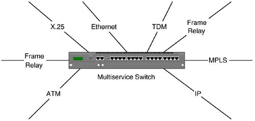
MPLS technology may be added as a firmware upgrade to such devices, or it may be included as a standard product component. This reflects the migration approach adopted for MPLS deployment: It can be switched on/off and used on an as-needed basis. In other words, a network operator can phase in the use of MPLS in conjunction with existing technologies such as ATM and FR. As the deployment (and planned deployment) of MPLS increases , the ability to smoothly (and slowly) apply its use in production networks is very useful. This is illustrated in Figure 8-1, where a multiservice switch supports a number of different technologies. Figure 8-1. A multi-service switch that supports MPLS. The multiservice switch in Figure 8-1 can originate and terminate a range of service types, such as Ethernet, X.25, TDM, IP, FR, and MPLS. Clearly, the switch is part of a broader network that supports these services. Over time, it is likely that such networks may migrate to just IP or possibly IP and MPLS. For this reason, it is important that the switch be capable of moving over to supporting just these service types without the need for expensive hardware upgrades. So, MPLS NEs implement the MPLS technology in firmware, and access to it is made through MPLS interfaces. The latter are described in the next section. MPLS InterfacesAn MPLS interface is one on which MPLS has already been configured and may include the following:
In the next section, we will see MPLS interfaces. MPLS Network ExampleFigure 8-2 illustrates MPLS interfaces with the letters A, B, C, and D, respectively. The lower half of the diagram has four more MPLS interfaces that have the following IP addresses: 5.5.4.1; 5.5.4.2; 5.5.5.1; and 5.5.5.2. This is the network that will be used for our MIB investigation. The ifIndex values for these interfaces are illustrated in parentheses. Also, interfaces in the lower half of the diagram are deliberately not labeled. Figure 8-2. An LSP and tunnel in an MPLS network. Figure 8-2 illustrates a four-node MPLS network that shares a boundary with an IP network. The MPLS network forwards real-time VoIP and non-real -time SMTP (email) traffic from one edge of the IP network in the direction of an adjacent subnetwork containing two gateways. Both sets of traffic are terminated on the latter devices. An LSP and a traffic-engineered tunnel have been configured in the MPLS network between the two edge nodes (LERs) with the core routers (LSRs) acting as transit nodes. The tunnel (called TE Tunnel in the diagram) is created using the TE MIB and the LSP is created using both the TE MIB and the LSR MIB. The TE Tunnel has been allocated sufficient bandwidth (640kbps) to simultaneously carry 10 uncompressed voice channels in its path . The LSP has no reserved bandwidth and offers a best-effort service level. Later in this chapter we show how the MIB is manipulated to create these entities. A noteworthy item of interest about the LSP and tunnel is that they originate and terminate inside the LERs rather than on the external interfaces. Each of them serves a destination IP address (or prefix). Incoming IP traffic lands on the Edge Router 1 and is then pushed into the appropriate tunnel or LSP. Which one should be used? That depends on the nature of the IP traffic; if it has been marked to receive better than best effort ( hop-by-hop ) forwarding, then it may take the path provided by the tunnel. The ingress LER makes the decision about the path taken by the packet by encapsulating it with an appropriate MPLS label ”one label for the LSP and another for the tunnel. The labeling decision may also be made based on any or all of the following:
The important point to note is that the labeling decision can be based on a rich combination of parameters. In the example of Figure 8-2, we take the most basic option because IP traffic is pushed into either the tunnel or LSP based only on the destination IP address. The policies that dictate traffic treatment are generally the network operator's responsibility. Each of the MPLS interfaces A, B, C, and D has a corresponding entry in the MIB table mplsInterfaceConfTable . The same is true of the unmarked interfaces in the lower half of Figure 8-2. The latter are not annotated in order to reduce clutter. An MPLS node would automatically populate this table with a row for each MPLS-capable interface. An entry in this table is illustrated in Figure 8-3. Please note that the MIB excerpts in the rest of the chapter take the form of SEQUENCE s of objects. These are ASN.1 constructs and are copied straight from the MIB definitions. The listed objects should be visualized as columns in a table (conceptually similar to a spreadsheet or a relational database table). Index objects are commented and appear in bold. Following a description of the MIB tables, we illustrate how the tables would be manipulated to create the LSP and tunnel objects in Figure 8-2. The software provided in Chapter 7 could be extended to achieve this ”that is, instead of addressing single MIB objects, the programs could address entire tables. Figure 8-3 The MPLS interface MIB table. MplsInterfaceConfEntry ::= SEQUENCE { mplsInterfaceConfIndex InterfaceIndexOrZero, -- Index mplsInterfaceLabelMinIn MplsLabel, mplsInterfaceLabelMaxIn MplsLabel, mplsInterfaceLabelMinOut MplsLabel, mplsInterfaceLabelMaxOut MplsLabel, mplsInterfaceTotalBandwidth MplsBitRate, mplsInterfaceAvailableBandwidth MplsBitRate, mplsInterfaceLabelParticipationType BITS } There is a relationship between the MPLS interface table and the interfaces.ifTable . This relationship is provided by the value of the mplsInterfaceConfIndex object . The range of MPLS label values that this interface can receive is indicated by the mplsInterfaceLabelMinIn and mplsInterfaceLabelMaxIn objects. The range of MPLS label values that this interface can send is indicated by the mplsInterfaceLabelMinOut and mplsInterfaceLabelMaxOut objects. The MplsLabel object is represented by four octets. Bits 0 to 19 represent the label with values supported, as we saw in Chapter 4, "Solving the Network Management Problem," Figure 4-10 ”for example, Explicit Null (0), Router Alert (1). The remaining 12 bits encode the Exp, Stack, and TTL fields. The total amount of usable bandwidth on this interface is indicated by mplsInterfaceTotalBandwidth and is specified in units of kilobits per second. The amount of bandwidth available at any given time is indicated by mplsInterfaceAvailableBandwidth ; this is the difference between mplsInterface-TotalBandwidth and the amount of bandwidth in use. The mplsInterfaceLabelParticipationType object dictates whether the label space is distributed across the platform or the interfaces. Per-platform label participation indicates that labels are globally allocated across the platform. Per-interface label participation indicates that each interface shares the label space with a specified range. In-SegmentsAn in-segment is the ingress leg of an LSP segment on a given MPLS NE. This is an object that controls the forwarding of packets into the LSP. Each of the in-segments on an MPLS node has a corresponding entry in the MIB table mplsInSegmentTable . An entry in this table is illustrated in Figure 8-4. Figure 8-4 The MPLS in-segment MIB table. MplsInSegmentEntry ::= SEQUENCE { mplsInSegmentIfIndex InterfaceIndexOrZero, -- Index mplsInSegmentLabel MplsLabel, -- Index mplsInSegmentNPop Integer32, mplsInSegmentAddrFamily AddressFamilyNumbers, mplsInSegmentXCIndex Unsigned32, mplsInSegmentOwner MplsInitialCreationSource , mplsInSegmentTrafficParamPtr RowPointer, mplsInSegmentRowStatus RowStatus, mplsInSegmentStorageType StorageType } This table is indexed by a combination of the ifIndex of the incoming interface and the topmost label, that is, mplsInSegmentIfIndex and mplsInSegmentLabel . The number of labels to pop is indicated by the value of mplsInSegmentNPop ; if this value is 2, then the node pops two labels off the stack. The mplsInSegmentAddrFamily gives the Internet Assigned Numbers Authority (IANA) address number; for instance, IPv4 has the value 1 and IPv6 is 2. The cross-connect associated with this segment is provided by the mplsInSegmentXCIndex . This is an index into the mplsXCTable . The mplsInSegmentOwner identifies the entity that created and owns this segment. The mplsInSegmentTrafficParamPtr indicates the entry (if any) in the mplsTrafficParamTable that contains the traffic details for this segment. The mplsInSegmentRowStatus is used when creating, modifying, or deleting an entry in this table. Its type is RowStatus , and the ways it can be used are described later in the section where we create an LSP. Finally, the storage type for the segment is described by mplsInSegmentStorageType . If this object has the value readOnly(5) , then a setRequest cannot delete or modify it. Out-SegmentsAn out-segment is the egress leg of an LSP segment on a given MPLS NE. This is an object that controls the forwarding of packets along the path of the LSP. Each of the out-segments on an MPLS node has a corresponding entry in the MIB table mplsOutSegmentTable . An entry in this table is illustrated in Figure 8-5. Figure 8-5 The MPLS out-segment MIB table. MplsOutSegmentEntry ::= SEQUENCE { mplsOutSegmentIndex Unsigned32, -- Index mplsOutSegmentIfIndex InterfaceIndexOrZero, mplsOutSegmentPushTopLabel TruthValue, mplsOutSegmentTopLabel MplsLabel, mplsOutSegmentNextHopIpAddrType InetAddressType, mplsOutSegmentNextHopIpAddr InetAddress, mplsOutSegmentXCIndex Unsigned32, mplsOutSegmentOwner MplsOwner , mplsOutSegmentTrafficParamPtr RowPointer, mplsOutSegmentRowStatus RowStatus, mplsOutSegmentStorageType StorageType } Entries in the out-segment table can be created based on index values obtained from the mplsOutSegmentIndexNext object. This object type is described later in this chapter. Once the index value is acquired , we can assign it to mplsOutSegmentIndex . The interface index of the outgoing interface is contained in mplsOutSegmentIfIndex . The boolean mplsOutSegmentPushTopLabel indicates if a label (the value of this label is found in mplsOutSegmentTopLabel ) should be pushed onto the stack of an outgoing MPLS packet. The outSegment is concerned with where to send an outgoing MPLS packet; the type of destination is indicated by the value of mplsOutSegmentNextHopIpAddrType and can be IPv4 (1) or IPv6 (2). The mplsOutSegmentNextHopIpAddr contains either the IPv4 or IPv6 address of the next hop, depending on the value of mplsOutSegmentNextHopIpAddrType . The mplsOutSegmentXCIndex indicates the cross-connect table entry with which this segment is associated. The mplsOutSegmentOwner identifies the entity that created and owns this segment. The mplsOutSegmentTrafficParamPtr indicates the entry (if any) in the mplsTrafficParamTable that contains the traffic details for this segment. The mplsOutSegmentRowStatus has semantics identical to the corresponding object in the in-segment table. The same is true for the mplsOutSegmentStorageType . Cross-ConnectsCross-connects are used to create associations between LSP segments. These associations serve as instructions for the MPLS NE to switch between the specified segments. The LSR MIB supports point-to-point, point-to-multipoint, and multipoint-to-point connections (we consider only point-to-point). Each of the cross-connects on an MPLS node has a corresponding entry in the MIB table mplsXCTable . An entry in this table is illustrated in Figure 8-6. Figure 8-6 The MPLS cross-connect MIB table. MplsXCEntry ::= SEQUENCE { mplsXCIndex Unsigned32, -- Index mplsXCInSegmentIfIndex InterfaceIndexOrZero, -- Index mplsXCInSegmentLabel MplsLabel, -- Index mplsXCOutSegmentIndex Unsigned32, -- Index mplsXCLspId MplsLSPID, mplsXCLabelStackIndex Unsigned32, mplsXCIsPersistent TruthValue, mplsXCOwner MplsOwner , mplsXCRowStatus RowStatus, mplsXCStorageType StorageType, mplsXCAdminStatus INTEGER, mplsXCOperStatus INTEGER } Entries in mplsXCTable can be created based on index values obtained from the mplsXCIndexNext object. The unique index value is assigned to mplsXCIndex . The mplsXCTable has an index made up of the first four objects in Figure 8-6. The object mplsXCInSegmentIfIndex represents the in-segment interface index for LSPs not originating on this node. For LSPs originating on this node, mplsXCInSegmentIfIndex is zero. The incoming label value on the cross-connect is mplsXCInSegmentLabel . The object mplsXCOutSegmentIndex is the out-segment index for LSPs passing through this node. For LSPs terminating on this node, mplsXCOutSegmentIndex is zero. The LSP to which this cross-connect belongs is indicated by the value of mplsXCLspId . The object mplsXCLabelStackIndex indicates an entry in the label stack table. This indicates the label stack that should be pushed onto the MPLS label. If this cross-connect must be restored after a failure (e.g., a faulty port card or a switch power failure), then the value of mplsXCIsPersistent should be set to true(1) . The value of mplsXCOwner identifies the entity that created and owns this cross-connect. The mplsXCAdminStatus object dictates the required administrative state of the cross-connect: up(1) means that packets can be forwarded. The value of mplsXCOperStatus is set only by the NE to indicate the actual operational status. If a failure occurs, then the value of mplsXCOperStatus should reflect it. This means that if an IP port card fails, then the LSP can no longer forward packets and the operational status should change to from up(1) to down(2) . Label StacksThe mplsLabelStackTable specifies the label stack to be pushed onto a packet. Entries to this table are referred to from mplsXCTable (via the mplsXCLabelStackIndex object). The topmost label is the one used by MPLS NEs for forwarding treatment. Labels beneath the topmost label become accessible when the topmost one is popped. This is useful when hierarchical routing behavior is required for a given packet; for example, let's say our label stack has two labels, label X and label Y. An IP packet arrives at MPLS Edge Router 1 in Figure 8-2. At this point the packet is MPLS-encoded and two labels are pushed, first X and then Y. The MPLS packet then proceeds to the next NE, but only the topmost label (Y) is used for forwarding treatment ”X remains unchanged. When the MPLS packet reaches the edge of our domain at MPLS Edge Router 2, the topmost label is popped and the remaining label (X) can then be popped and used for additional routing. This type of hierarchical arrangement could be used when routing packets across transit SP networks, such as Interexchange Carriers (IXCs). An entry in this table is illustrated in Figure 8-7. Figure 8-7 The MPLS label stack MIB table. MplsLabelStackEntry ::= SEQUENCE { mplsLabelStackIndex Unsigned32, -- Index mplsLabelStackLabelIndex Unsigned32, -- Secondary Index mplsLabelStackLabel MplsLabel, mplsLabelStackRowStatus RowStatus, mplsLabelStackStorageType StorageType } Again, mplsLabelStackIndexNext is sampled to give the next free index in this table. This value can then be assigned to mplsLabelStackIndex . The object mplsLabelStackLabelIndex is a secondary index indicating position within the label stack. A smaller value of MplsLabelStackLabelIndex indicates entries higher up the stack. MplsLabelStackLabel is the label to be pushed onto the packet. Traffic ParametersThis table specifies the characteristics of traffic parameter objects for in-segments and out-segments. An entry in this table is illustrated in Figure 8-8. Figure 8-8 The MPLS traffic parameter MIB table. MplsTrafficParamEntry ::= SEQUENCE { mplsTrafficParamIndex Unsigned32, -- Index mplsTrafficParamMaxRate MplsBitRate, mplsTrafficParamMeanRate MplsBitRate, mplsTrafficParamMaxBurstSize MplsBurstSize, mplsTrafficParamRowStatus RowStatus, mplsTrafficParamStorageType StorageType } Entries in this table can be created by use of the mplsTrafficParamIndexNext object. The value of the latter can be assigned to mplsTrafficParamIndex . Each entry in this table can be viewed as a profile that describes the bandwidth characteristics of the associated LSP. The maximum rate in units of kilobits per second is indicated by the value of mplsTrafficParamMaxRate . This is the maximum required rate of packet forwarding. Similarly, the mean rate in units of kilobits per second is indicated by the value of mplsTrafficParamMeanRate . This is the required average rate of packet forwarding. The maximum burst size in bytes is indicated by the value of mplsTrafficParamMaxBurstSize . This is the required maximum burst size expected. PerformanceThe LSR MIB includes a number of performance counters. One of these is the mplsInterfacePerfTable , which provides an entry for every interface on the LSR capable of supporting MPLS. This table augments the mplsInterfaceConfEntry discussed in Figure 8-3. An entry in this table is illustrated in Figure 8-9. Figure 8-9 The MPLS interface performance MIB table. MplsInterfacePerfEntry ::= SEQUENCE { mplsInterfaceInLabelsUsed Gauge32, mplsInterfaceFailedLabelLookup Counter32, mplsInterfaceOutLabelsUsed Gauge32, mplsInterfaceOutFragments Counter32 } The mplsInterfaceInLabelsUsed object counts the number of labels that are in use at this point in time on this interface in the incoming direction. The object mplsInterfaceFailedLabelLookup counts the number of MPLS packets that have been received on this interface and were discarded because no matching cross-connect entry was found. Each such occurrence is commonly called a label fault. The object mplsInterfaceOutLabelsUsed counts the number of top-most labels in the outgoing label stacks that are in use at this point in time on this interface. The object mplsInterfaceOutFragments counts the number of outgoing MPLS packets that required fragmentation before transmission on this interface. |
EAN: 2147483647
Pages: 150