Smarter NMS
| There is always scope for improving technical software products, and NMS are no exception. NMS must increasingly support high levels of
Much can be done to improve NMS so that they consume minimal NE resources:
When the NMS user issues commands that result in network-bound SNMP messages, it may be advantageous to create batches. These are condensed SNMP messages that seek to minimize the overall number of get s and set s by aggregating MIB objects. So, rather than sending ten getRequest messages to one NE, it is more efficient to send one message with ten MIB object bindings. A specific NMS middleware layer would execute this function transparently . When static data is discovered , there may be a large number of get s sent to the network. Rather than an expensive (and ongoing) rediscovery of all data, the MIBs should allow for the indication of modified objects. This allows the NMS to rediscover only data that has changed (similar to the way disk backup software can apply incremental backups of only files that have changed rather than of all files). This reduces the cost of maintaining parity between the network and the NMS. Deterministic performance is another important NMS aspect. This requires a fully profiled codebase so that adding 100 new NEs to the user network adds a known load to the NMS. To a large extent it is almost impossible to know the exact resources required for supporting a given NE. Any device can suddenly suffer a failure (e.g., several port cards failing at the same time) and start to emit large numbers of notifications. Likewise (in the opposite direction), provisioning operations may start to time out because the NE/agent is heavily loaded, the network is congested , or timeout thresholds have been set too low. Adding Services ManagementService management is an increasingly popular topic with vendors [NMSGotham], [NMSHPOV]. In this the service offered to the user is managed rather than the operator being concerned with just the underlying connections in its network domains (access, distribution, and core ). The NMS offers a higher-level service management capability, such as layer 2 (e.g., Ethernet) over an MPLS backbone. The rationale is that users want services rather than technology like ATM connections (this is closely allied to the above-mentioned solution orientation). So, it makes sense for NMS to be able to deal in terms of services rather than just connections and devices. Service management introduces a new paradigm that is not restricted to a single connection. A service can be made up of more than one connection and even more than one type of cross-connection object. For this reason, service management generally requires a new type of managed object for:
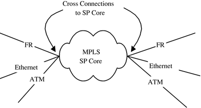
An interesting aspect of MPLS is that it will allow enterprise network cores to become more generic. Regardless of traffic type (layer 2 or 3), it will be transported over LSPs/tunnels. A more generic core allows for more easily offering different service levels. Multiservice switches help facilitate this type of arrangement by allowing easy cross-connection of technologies such as Ethernet, FR, and ATM into an SP core. This is illustrated in Figure 4-2 with a range of access link types terminating on the edge of an SP network. The various links terminate at multiservice switch ports and are then cross-connected into the core. Figure 4-2. SP core network with cross connections. Service management still involves connections in the underlying network, but this is deliberately obscured (or abstracted away) by the NMS in order to simplify the network picture. A number of issues arise if scalable service management is to be offered because NEs must provide:
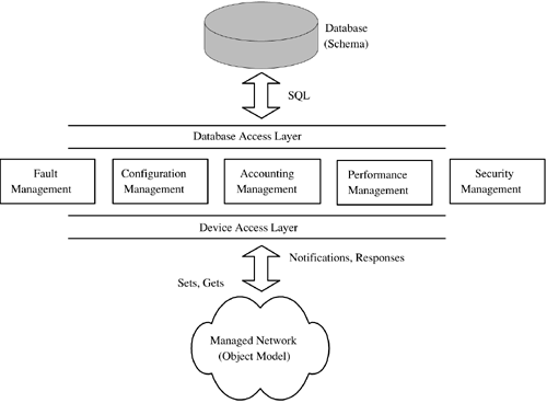
Implementing services is difficult in a network comprised of several different domains, such as ATM, IP, MPLS, Frame Relay, and X.25. Connections, such as ATM/Frame Relay PVCs, can be manually joined together as they are created (by first creating an ATM PVC on port X and then an associated Frame Relay interworking). However, automatically creating end-to-end, cross-domain connections requires special signaling protocols in the NEs. These protocols would allow the creation of multidomain, managed service connections. This becomes a more pressing problem as MPLS starts to be deployed in network cores (along with ATM and SONET/SDH) because more and more protocols will then move to the edge of the network and have to be interworked or cross-connected. The emerging standard Pseudo Wire Emulation Edge-to-Edge (PWE3) [IETF-PWE3] will allow generic layer 2 emulation across MPLS cores. In time, this may well assist service management. In advance of service management infrastructure such as multidomain signaling and PWE3, existing NMS can still offer a limited and fairly scalable form of service management. This consists of discovery and provisioning of just the first leg of a cross-connected service. This is just the head end of the service, which in Figure 4-2 is the leftmost cross-connection. If the head-end host node maintains the operational status of the overall service, then this can be monitored by the NMS. However, the individual downstream segments of the service are not monitored for status changes in the interests of scalability (there may be many downstream segments, so the NMS essentially ignores them and takes its cue from the head end only). Once the network becomes service-aware (with multidomain signaling, PWE3, etc.), its NEs can then emit service-level traps. In Figure 4-2, a multiservice connection starts as Frame Relay, crosses an MPLS core, and exits as Frame Relay again. If a node or link in the path of this connection fails, then only one trap is needed by the NMS. The head-end node at the point of origination of the Frame Relay service can emit this trap. It is not absolutely necessary for all affected nodes to generate traps for this. Reducing the number of traps improves scalability, particularly if the traps accurately describe the problem and its location. NMS StructureMost NMS are vertical applications. Generally implemented in what is often called a stovepipe fashion, data flows are up and down the paths illustrated in Figure 4-3. Figure 4-3. NMS stovepipes. Each application in Figure 4-3 tends to be distinct, sharing some data (such as node details) about the network but essentially being standalone. There is little, if any, horizontal communication between the stovepipes because they are both database- and NE-centric and fulfill specific FCAPS functions. Figure 4-3 illustrates the baseline FCAPS structure. Real NMS tend to have additional software for facilities, such as
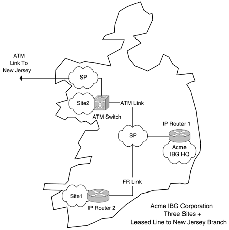
The version of firmware running on a given NE is an important piece of information. As new features (or bug fixes to existing ones) are required in the network, it frequently is necessary to distribute new firmware versions to the NEs. An NMS can provide this facility as well as back up the existing version (in case the new code has problems, e.g., insufficient NE RAM/flash, software bugs ) and store it in a safe location. The topology data can then be updated to indicate the new firmware version. The NMS can also distribute firmware to more than one NE simultaneously if required (this can reduce network/NE downtime). NE configuration data is also vital because it dictates how the features operate in the network. Many NMS provide the ability to backup and restore configuration data. Topology management can take the form of supporting a pictorial representation of the network. Often, this is implemented against a geographical background showing the location of NEs relative to their physical location. This is illustrated in Figure 4-4 for a hypothetical three-site enterprise called Acme IBG Corporation located in Ireland. This enterprise has a central site (HQ), and WAN connections go from it to the branch offices. The intersite links are SP-owned. Any of the nodes, links, and clouds in Figure 4-4 can become faulted:
Figure 4-4. Network topology with geographical mapping. Faults can be visually indicated by means of changing the color of some GUI object. Topology components may contain subordinate objects. For example,
Above the level of abstraction associated with a node are clouds. Clouds can contain any number of subordinate network objects (including other clouds). An important consideration for reflecting network status in a topology application is the way in which faults are visually rendered. If a topology application is displaying just network clouds ”that is, the topmost level of the hierarchy ”then a node fault (notification) in one of the clouds should be visible. Normally, the fault results in a color change in its container cloud. As usual, the quality of the overall NMS dictates the speed with which the fault is registered. The user should be able to select (using a mouse or other pointing device) the faulted cloud and drill down to see the exact location of the problem. Some NMS may employ additional methods of announcing faults, for example, by sending mobile telephony short text messages, pager alerts, or email to operators. Usually, an NMS deployed inside one of the clouds monitors and controls the NEs in Figure 4-4. Chapter 5, "A Real NMS," examines the components of a commercial NMS. |
EAN: 2147483647
Pages: 150


