The Windows GDI
In a single-tasking environment such as MS-DOS, the name of the game when it comes to screen output is "anything goes." A running application is free to do just about whatever it wants whenever it wants, whether that involves drawing a line on the screen, reprogramming the adapter's color palette, or switching to another video mode. In a windowed, multitasking environment such as Windows, programs can't be afforded such freedom because the output from program A must be protected from the output of program B. First and foremost, this means that each program's output must be restricted to its own window. The GDI uses a simple mechanism to make sure every program that draws in a window plays by the rules. That mechanism is the device context.
When a Windows program draws to a screen, a printer, or any other output device, it doesn't output pixels directly to the device. Instead, it draws to a logical "display surface" represented by a device context (DC). A device context is a data structure deep inside Windows that contains fields describing everything the GDI needs to know about the display surface, including the physical device with which it is associated and assorted state information. Before it draws anything on the screen, a Windows program acquires a device context handle from the GDI. It then passes that handle back to the GDI each time it calls a GDI output function. Without a valid device context handle, the GDI won't draw the first pixel. And through the device context, the GDI can make sure that everything the program draws is clipped to a particular area of the screen. Device contexts play a huge role in making the GDI device-independent because, given a handle to a device context, the same GDI functions can be used to draw to a diverse assortment of output devices.
When you program Windows with MFC, the device context has even greater significance. In addition to serving as the key that unlocks the door to output devices, a device context object encapsulates the GDI functions that programs use to generate output. In MFC, you don't grab a handle to a device context and call GDI output functions, at least not directly; instead, you create a device context object and call its member functions to do your drawing. MFC's CDC class wraps a Windows device context and the GDI functions that require a device context handle into one convenient package, and CDC-derived classes such as CPaintDC and CClientDC represent the different types of device contexts that Windows applications use.
The MFC Device Context Classes
One way to get a device context in an MFC application is to call CWnd::GetDC, which returns a pointer to a CDC object representing a Windows device context. A device context pointer acquired with CWnd::GetDC should be released with CWnd::ReleaseDC when drawing is completed. The following code gets a CDC pointer from GetDC, does some drawing, and calls ReleaseDC to release the device context:
CDC* pDC = GetDC (); // Do some drawing ReleaseDC (pDC); |
If the same code were to appear in an OnPaint handler, you would use CWnd::BeginPaint and CWnd::EndPaint in place of GetDC and ReleaseDC to ensure proper handling of the WM_PAINT message:
PAINTSTRUCT ps; CDC* pDC = BeginPaint (&ps); // Do some drawing EndPaint (&ps); |
The GDI also supports metafiles, which store sequences of GDI commands that can be "played back" to produce physical output. To acquire a device context for a metafile's output, you would use yet another set of functions to obtain and release the CDC pointer. And to acquire a CDC pointer for a device context that permits drawing anywhere in the window (as opposed to one that permits drawing only in the window's client area), you would call CWnd::GetWindowDC rather than GetDC and release the device context with ReleaseDC.
To save you the trouble of having to remember which functions to call to acquire and release a device context (and to help ensure that a device context is properly released when the message handler that uses the device context ends), MFC provides the CDC-derived classes listed in the following table.
Special-Purpose Device Context Classes
| Class Name | Description |
|---|---|
| CPaintDC | For drawing in a window's client area (OnPaint handlers only) |
| CClientDC | For drawing in a window's client area (anywhere but OnPaint) |
| CWindowDC | For drawing anywhere in a window, including the nonclient area |
| CMetaFileDC | For drawing to a GDI metafile |
These classes are designed to be instantiated directly. Each class's constructor and destructor call the appropriate functions to get and release the device context so that using a device context is no more complicated than this:
CPaintDC dc (this); // Do some drawing |
The pointer passed to the class constructor identifies the window that the device context pertains to.
When a device context object is constructed on the stack, its destructor is called automatically when the object goes out of scope. And when the destructor is called, the device context is released back to Windows. The only time you need to be concerned about releasing one of these device contexts yourself is when (and if) you create a device context object on the heap with new, as shown here:
CPaintDC* pDC = new CPaintDC (this); |
In this case, it's important to execute a
delete pDC; |
statement before the function that created the device context ends so that the object's destructor will be called and the device context will be released. On some occasions, it's useful to create a device context on the heap rather than on the stack, but generally you're a lot better off creating device context objects on the stack and letting the compiler do the deleting for you.
The CPaintDC Class
MFC's CPaintDC class lets you paint in a window's client area in response to WM_PAINT messages. You should use it only in OnPaint handlers and never anywhere else. WM_PAINT messages are different from all other Windows messages in one very important respect: If the handler fails to call the Windows ::BeginPaint and ::EndPaint functions (or the MFC equivalents, CWnd::BeginPaint and CWnd::EndPaint), the message will not be removed from the message queue no matter how much drawing you do. Consequently, the application will get stuck processing the same WM_PAINT message over and over. CPaintDC virtually ensures that this won't happen by calling ::BeginPaint and ::EndPaint from its constructor and destructor, respectively.
The CClientDC and CWindowDC Classes
Windows programs don't always limit their painting to OnPaint. If you write an application that draws a circle on the screen whenever a mouse button is clicked, you'll probably want to paint the circle immediately—when you receive the button-click message—rather than wait for the next WM_PAINT message.
That's what MFC's CClientDC class is for. CClientDC creates a client-area device context that can be used outside OnPaint. The following message handler uses CClientDC and two CDC member functions to draw an X connecting the corners of the window's client area when the left mouse button is clicked:
void CMainWindow::OnLButtonDown (UINT nFlags, CPoint point) { CRect rect; GetClientRect (&rect); CClientDC dc (this); dc.MoveTo (rect.left, rect.top); dc.LineTo (rect.right, rect.bottom); dc.MoveTo (rect.right, rect.top); dc.LineTo (rect.left, rect.bottom); } |
left, right, top, and bottom are public member variables defined in MFC's CRect class. They store the coordinates of the rectangle's four sides. MoveTo and LineTo are line-drawing functions that CClientDC inherits from CDC. You'll learn more about these two functions in a moment.
For the rare occasions on which you'd like to paint not only the window's client area but also the nonclient area (the title bar, the window border, and so on), MFC provides the CWindowDC class. CWindowDC is similar to CClientDC, but the device context it represents encompasses everything within the window's borders. Programmers sometimes use CWindowDC for unusual effects such as custom-drawn title bars and windows with rounded corners. In general, you won't need CWindowDC very often. If you do want to do your own painting in a window's nonclient area, you can trap WM_NCPAINT messages with an OnNcPaint handler to determine when the nonclient area needs to be painted. Unlike OnPaint, an OnNcPaint handler need not (and should not) call BeginPaint and EndPaint.
For the even rarer occasions on which a program requires access to the entire screen, you can create a CClientDC or CWindowDC object and pass its constructor a NULL pointer. The statements
CClientDC dc (NULL); dc.Ellipse (0, 0, 100, 100); |
draw a circle in the upper left corner of the screen. Screen capture programs frequently use full-screen DCs to access the whole screen. Needless to say, drawing outside your own window is a very unfriendly thing to do unless you have a specific reason for doing so.
Device Context Attributes
When you draw to the screen with CDC output functions, certain characteristics of the output aren't specified in the function call but are obtained from the device context itself. When you call CDC::DrawText, for example, you specify the text string and the rectangle in which the string will appear, but you don't specify the text color or the font because both are attributes of the device context. The following table lists some of the most useful device context attributes and the CDC functions used to access them.
Key Device Context Attributes
| Attribute | Default | Set with | Get with |
|---|---|---|---|
| Text color | Black | CDC::SetTextColor | CDC::GetTextColor |
| Background color | White | CDC::SetBkColor | CDC::GetBkColor |
| Background mode | OPAQUE | CDC::SetBkMode | CDC::GetBkMode |
| Mapping mode | MM_TEXT | CDC::SetMapMode | CDC::GetMapMode |
| Drawing mode | R2_COPYPEN | CDC::SetROP2 | CDC::GetROP2 |
| Current position | (0,0) | CDC::MoveTo | CDC::GetCurrentPosition |
| Current pen | BLACK_PEN | CDC::SelectObject | CDC::SelectObject |
| Current brush | WHITE_BRUSH | CDC::SelectObject | CDC::SelectObject |
| Current font | SYSTEM_FONT | CDC::SelectObject | CDC::SelectObject |
Different CDC output functions use device context attributes in different ways. For example, when you draw a line with LineTo, the current pen determines the line's color, width, and style (solid, dotted, dashed, and so on). Similarly, when you draw a rectangle with the Rectangle function, the GDI borders the rectangle with the current pen and fills the rectangle with the current brush. All text output functions use the current font. The text color and the background color control the colors used when text is output. The text color determines the color of the characters, and the background color determines what color is used to fill behind them. The background color is also used to fill the gaps between line segments when dotted or dashed lines are drawn with the LineTo function and to fill the open areas between hatch marks painted by a hatch brush. If you'd like the background color to be ignored entirely, you can set the background mode to "transparent," like this:
dc.SetBkMode (TRANSPARENT); |
Inserting this statement before the call to DrawText in Chapter 1's Hello program eliminates the white rectangle surrounding "Hello, MFC" that's visible when the window background color is nonwhite.
The CDC function you'll use more than any other to modify the attributes of a device context is SelectObject. The following six items are GDI objects that can be selected into a device context with SelectObject:
- Pens
- Brushes
- Fonts
- Bitmaps
- Palettes
- Regions
In MFC, pens, brushes, and fonts are represented by the classes CPen, CBrush, and CFont. (Bitmaps, palettes, and regions are discussed in Chapter 15.) Unless you call SelectObject to change the current pen, brush, or font, the GDI uses the device context's defaults. The default pen draws solid black lines 1 pixel wide. The default brush paints solid white. The default font is a rather plain proportional font with a height of roughly 12 points. You can create pens, brushes, and fonts of your own and select them into a device context to change the attributes of the output. To draw a solid red circle with a 10-pixel-wide black border, for example, you can create a black pen 10 pixels wide and a red brush and select them into the device context with SelectObject before calling Ellipse. If pPen is a pointer to a CPen object, pBrush is a pointer to a CBrush object, and dc represents a device context, the code might look like this:
dc.SelectObject (pPen); dc.SelectObject (pBrush); dc.Ellipse (0, 0, 100, 100); |
SelectObject is overloaded to accept pointers to objects of various types. Its return value is a pointer to the object of the same type that was previously selected into the device context.
Each time you acquire a device context from Windows, its attributes are reset to the defaults. Consequently, if you want to use a red pen and a blue brush to paint your window in response to WM_PAINT messages, you must select them into the device context each time OnPaint is called and a new CPaintDC object is created. Otherwise, the default pen and brush will be used. If you'd like to avoid reinitializing a device context every time you use it, you can save its state with the CDC::SaveDC function and restore it the next time around with CDC::RestoreDC. Another option is to register a custom WNDCLASS that includes the CS_OWNDC style, which causes Windows to allocate to each instance of your application its own private device context that retains its settings. (A related but seldom used WNDCLASS style, CS_CLASSDC, allocates a "semiprivate" device context that is shared by all windows created from the same WNDCLASS.) If you select a red pen and a blue brush into a private device context, they remain selected until they're explicitly replaced.
The Drawing Mode
When the GDI outputs pixels to a logical display surface, it doesn't simply output pixel colors. Rather, it combines the colors of the pixels that it's outputting with the colors of the pixels at the destination using a combination of Boolean operations. The logic that's employed depends on the device context's current drawing mode, which you can change with CDC::SetROP2 (short for "Set Raster Operation To"). The default drawing mode is R2_COPYPEN, which does, in fact, copy pixels to the display surface. But there are 15 other drawing modes to choose from, as shown in the table below. Together, these drawing modes represent all the possible operations that can be performed by combining the Boolean primitives AND, OR, XOR, and NOT.
Why would you ever need to change the drawing mode? Suppose you want to draw a line not by copying pixels to the display surface but by inverting the colors of the pixels already there. It's easy to do; you just set the drawing mode to R2_NOT before drawing the line:
dc.SetROP2 (R2_NOT); dc.MoveTo (0, 0); dc.LineTo (100, 100); |
This little trick might be more useful than you think, because it's a great way to rubber-band lines and rectangles. You'll see an example of what I mean in Chapter 3.
GDI Drawing Modes
| Drawing Mode | Operation(s) Performed |
|---|---|
| R2_NOP | dest = dest |
| R2_NOT | dest = NOT dest |
| R2_BLACK | dest = BLACK |
| R2_WHITE | dest = WHITE |
| R2_COPYPEN | dest = src |
| R2_NOTCOPYPEN | dest = NOT src |
| R2_MERGEPENNOT | dest = (NOT dest) OR src |
| R2_MASKPENNOT | dest = (NOT dest) AND src |
| R2_MERGENOTPEN | dest = (NOT src) OR dest |
| R2_MASKNOTPEN | dest = (NOT src) AND dest |
| R2_MERGEPEN | dest = dest OR src |
| R2_NOTMERGEPEN | dest = NOT (dest OR src) |
| R2_MASKPEN | dest = dest AND src |
| R2_NOTMASKPEN | dest = NOT (dest AND src) |
| R2_XORPEN | dest = src XOR dest |
| R2_NOTXORPEN | dest = NOT (src XOR dest) |
The Mapping Mode
Without a doubt, the aspect of GDI programming that new Windows programmers find the most confusing is the mapping mode. Simply put, the mapping mode is the attribute of the device context that governs how logical coordinates are translated into device coordinates. Logical coordinates are the coordinates you pass to CDC output functions. Device coordinates are the corresponding pixel positions within a window. When you call the Rectangle function like this:
dc.Rectangle (0, 0, 200, 100); |
you're not necessarily telling the GDI to draw a rectangle that's 200 pixels wide and 100 pixels tall; you're telling it to draw a rectangle that's 200 units wide and 100 units tall. In the default mapping mode, MM_TEXT, it just so happens that 1 unit equals 1 pixel. But in other mapping modes, logical units are translated into device units differently. In the MM_LOENGLISH mapping mode, for example, 1 unit equals 1/100 of an inch. Therefore, drawing a rectangle that measures 200 units by 100 units in the MM_LOENGLISH mapping mode produces a 2-inch by 1-inch rectangle. Using a non-MM_TEXT mapping mode is a convenient way to scale your output so that sizes and distances are independent of the output device's physical resolution.
Windows supports eight different mapping modes. Their properties are summarized in the following table.
GDI Mapping Modes
| Mapping Mode | Distance Corresponding to One Logical Unit | Orientation of the x and y Axes |
|---|---|---|
| MM_TEXT | 1 pixel |  |
| MM_LOMETRIC | 0.1 mm |  |
| MM_HIMETRIC | 0.01 mm |  |
| MM_LOENGLISH | 0.01 in. |  |
| MM_HIENGLISH | 0.001 in. |  |
| MM_TWIPS | 1/1440 in. (0.0007 in.) |  |
| MM_ISOTROPIC | User-defined (x and y scale identically) | User-defined |
| MM_ANISOTROPIC | User-defined (x and y scale independently) | User-defined |
When you draw in the MM_TEXT mapping mode, you're using the coordinate system shown in Figure 2-1. The origin is in the upper left corner of the window, the positive x axis points to the right, the positive y axis points downward, and 1 unit equals 1 pixel. If you switch to one of the "metric" mapping modes—MM_LOENGLISH, MM_HIENGLISH, MM_LOMETRIC, MM_HIMETRIC, or MM_TWIPS—the y axis flips so that positive y points upward and logical units are scaled to represent real distances rather than raw pixel counts. The origin, however, remains in the upper left corner. One thing to remember when using a metric mapping mode is that you must use negative y values if you want to see your output. The statement
dc.Rectangle (0, 0, 200, 100); |
draws a 200-pixel by 100-pixel rectangle in the MM_TEXT mapping mode. The same statement produces no output in the MM_LOENGLISH mapping mode because positive y coordinates lie outside the visible part of the window. To make the rectangle visible, you must negate the y coordinates, as shown here:
dc.Rectangle (0, 0, 200, -100); |
If you switch to a non-MM_TEXT mapping mode and suddenly your application's output is no longer visible, check the sign of your y coordinates. Positive y coordinates will be the problem almost every time.
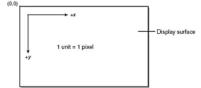
Figure 2-1. The MM_TEXT coordinate system.
The default mapping mode is MM_TEXT. If you want to use one of the other mapping modes, you must call CDC::SetMapMode to change the mapping mode. The following statements switch to the MM_LOMETRIC mapping mode and draw an ellipse whose major axis is 5 centimeters long and whose minor axis measures 3 centimeters:
dc.SetMapMode (MM_LOMETRIC); dc.Ellipse (0, 0, 500, -300); |
You can see that there's really nothing tricky about mapping modes. Things get slightly more complicated when you use the MM_ISOTROPIC and MM_ANISOTROPIC modes and when you do hit-testing on objects drawn in non-MM_TEXT mapping modes, but even that doesn't have to be difficult. The MM_ISOTROPIC and MM_ANISOTROPIC mapping modes are discussed in the next section.
One thing to keep in mind when you use the metric mapping modes is that on display screens, 1 logical inch usually doesn't equal 1 physical inch. In other words, if you draw a line that's 100 units long in the MM_LOENGLISH mapping mode, the line probably won't be exactly 1 inch long. The reason? Windows doesn't know the physical resolution of your monitor—the number of dots per inch (dpi) it's capable of displaying horizontally and vertically. (This might change in a future version of Windows.) The same is not true of printers and other hardcopy devices, however. The printer driver knows that a 600 dpi laser printer can print exactly 600 dots per inch, so a 100-unit line drawn in the MM_LOENGLISH mapping mode will measure exactly 1 inch on the printed page.
Programmable Mapping Modes
The MM_ISOTROPIC and MM_ANISOTROPIC mapping modes differ from the other mapping modes in one important respect: It's you, not Windows, who determines how logical coordinates are converted into device coordinates. For this reason, these mapping modes are sometimes called the "roll-your-own" or "programmable" mapping modes. Want a mapping mode in which 1 unit equals 1 centimeter? No problem: Just use the MM_ANISOTROPIC mapping mode and set its scaling parameters accordingly.
The most common use for the MM_ISOTROPIC and MM_ANISOTROPIC mapping modes is for drawing output that automatically scales to match the window size. The following code fragment uses the MM_ANISOTROPIC mapping mode to draw an ellipse that touches all four borders of the window in which it is drawn:
CRect rect; GetClientRect (&rect); dc.SetMapMode (MM_ANISOTROPIC); dc.SetWindowExt (500, 500); dc.SetViewportExt (rect.Width (), rect.Height ()); dc.Ellipse (0, 0, 500, 500); |
See how it works? No matter what physical size the window is, you've told Windows that the window's logical size is 500 units by 500 units. Therefore, a bounding box that stretches from (0,0) to (500,500) encompasses the entire window. Initializing a device context in this way places the origin at the upper left corner of the window and orients the axes so that positive x points to the right and positive y points downward. If you'd rather have the y axis point upward (as it does in the metric mapping modes), you can reverse its direction by negating the y value passed to either SetWindowExt or SetViewportExt:
CRect rect; GetClientRect (&rect); dc.SetMapMode (MM_ANISOTROPIC); dc.SetWindowExt (500, -500); dc.SetViewportExt (rect.Width (), rect.Height ()); dc.Ellipse (0, 0, 500, -500); |
Now you must use negative y coordinates to draw in the window. Only the MM_ISOTROPIC and MM_ANISOTROPIC mapping modes allow the directions of the x and y axes to be reversed. That's why the table in the previous section listed these two mapping modes' axis orientations as user defined.
The only difference between the MM_ISOTROPIC and MM_ANISOTROPIC mapping modes is that in the former, the scaling factors for the x and y directions are always the same. In other words, 100 horizontal units equals the same physical distance as 100 vertical units. Isotropic means "equal in all directions." The MM_ISOTROPIC mapping mode is ideal for drawing circles and squares. The following code draws a circle that spans the width or height of a window, whichever is smaller:
CRect rect; GetClientRect (&rect); dc.SetMapMode (MM_ISOTROPIC); dc.SetWindowExt (500, 500); dc.SetViewportExt (rect.Width (), rect.Height ()); dc.Ellipse (0, 0, 500, 500); |
As far as Windows is concerned, the window's logical size is once again 500 units by 500 units. But now the GDI takes the output device's aspect ratio into consideration when converting logical units to device units. Chapter 14's Clock program uses the MM_ISOTROPIC mapping mode to draw a round clock face and to automatically scale the clock size to the window size. Without the MM_ISOTROPIC mapping mode, Clock would have to do all of the scaling manually.
Let's talk a bit about the SetWindowExt and SetViewportExt functions. Officially, SetWindowExt sets the "window extents" and SetViewportExt sets the "viewport extents." Think of a window as something whose size is measured in logical units and a viewport as something whose size is measured in device units, or pixels. When Windows converts between logical coordinates and device coordinates, it uses a pair of formulas that factor in the window's logical dimensions (the window extents) and its physical dimensions (the viewport extents) as well as the location of the origin. When you set the window extents and viewport extents, you're effectively programming in your own scaling parameters. Generally, the viewport extents are simply the size (in pixels) of the window you're drawing in and the window extents are the window's desired size in logical units.
One caveat regarding the use of SetWindowExt and SetViewportExt is that in the MM_ISOTROPIC mapping mode, you should call SetWindowExt first. Otherwise, a portion of the window's client area might fall outside the window's logical extents and become unusable. In the MM_ANISOTROPIC mapping mode, it doesn't matter which are set first—the window extents or the viewport extents.
Coordinate Conversions
You can translate logical coordinates to device coordinates using the CDC::LPtoDP function. Conversely, you can translate device coordinates to logical coordinates with CDC::DPtoLP.
Let's say you want to know where the center of a window is in device coordinates. All you have to do is halve the window's pixel width and height. CWnd::GetClientRect returns a window's pixel dimensions.
CRect rect; GetClientRect (&rect); CPoint point (rect.Width () / 2, rect.Height () / 2); |
If you want to know where the center point is in MM_LOENGLISH units, however, you need DPtoLP:
CRect rect; GetClientRect (&rect); CPoint point (rect.Width () / 2, rect.Height () / 2); CClientDC dc (this); dc.SetMapMode (MM_LOENGLISH); dc.DPtoLP (&point); |
When DPtoLP returns, point holds the coordinates of the center point in logical (that is, MM_LOENGLISH) coordinates. If, on the other hand, you want to know the pixel coordinates of the point whose MM_LOENGLISH coordinates are (100,100), you use LPtoDP:
CPoint point (100, 100); CClientDC dc (this); dc.SetMapMode (MM_LOENGLISH); dc.LPtoDP (&point); |
One situation in which LPtoDP and DPtoLP are indispensable is when you're performing hit-testing in response to mouse clicks. Mouse clicks are always reported in device coordinates, so if you've drawn a rectangle in MM_LOENGLISH coordinates and you want to know whether a mouse click occurred inside that rectangle, you must either convert the rectangle's coordinates to device coordinates or convert the click coordinates to logical coordinates. Otherwise, you'll be comparing apples and oranges.
Moving the Origin
By default, a device context's origin is in the upper left corner of the display surface. Even if you change the mapping mode, the origin remains in the upper left corner. But just as you can change the mapping mode, you can also move the origin. MFC's CDC class provides two functions for moving the origin. CDC::SetWindowOrg moves the window origin, and CDC::SetViewportOrg moves the viewport origin. You'll normally use one but not both. Using both can be very confusing.
Suppose you'd like to move the origin to the center of the window so that you can center what you draw by centering your output around the point (0,0). Assuming that dc is a device context object, here's one way to do it:
CRect rect; GetClientRect (&rect); dc.SetViewportOrg (rect.Width () / 2, rect.Height () / 2); |
Here's another way to accomplish the same thing, assuming that you're working in the MM_LOENGLISH mapping mode:
CRect rect; GetClientRect (&rect); CPoint point (rect.Width () / 2, rect.Height () / 2); dc.SetMapMode (MM_LOENGLISH); dc.DPtoLP (&point); dc.SetWindowOrg (-point.x, -point.y); |
It's easy to get SetViewportOrg and SetWindowOrg confused, but the distinction between them is actually quite clear. Changing the viewport origin to (x,y) with SetViewportOrg tells Windows to map the logical point (0,0) to the device point (x,y). Changing the window origin to (x,y) with SetWindowOrg does essentially the reverse, telling Windows to map the logical point (x,y) to the device point (0,0)—the upper left corner of the display surface. In the MM_TEXT mapping mode, the only real difference between the two functions is the signs of x and y. In other mapping modes, there's more to it than that because SetViewportOrg deals in device coordinates and SetWindowOrg deals in logical coordinates. You'll see examples of how both functions are used later in this chapter.
As a final example, suppose you're drawing in the MM_HIMETRIC mapping mode, where 1 unit equals 1/100 of a millimeter, positive x points to the right, and positive y points upward, and you'd like to move the origin to the lower left corner of the window. Here's an easy way to do it:
CRect rect; GetClientRect (&rect); dc.SetViewportOrg (0, rect.Height ()); |
Now you can draw with positive x and y values using coordinates relative to the window's lower left corner.
A Final Word on Coordinate Systems
When you talk about mapping modes, window origins, viewport origins, and other idioms related to the GDI's handling of coordinates, it's easy to get tangled up in the terminology. Understanding the difference between the device coordinate system and the logical coordinate system might help clear some of the cobwebs.
In the device coordinate system, distances are measured in pixels. The device point (0,0) is always in the upper left corner of the display surface, and the positive x and y axes always point right and downward. The logical coordinate system is altogether different. The origin can be placed anywhere, and both the orientation of the x and y axes and the scaling factor (the number of pixels that correspond to 1 logical unit) vary with the mapping mode. To be precise, they vary with the window extents and the viewport extents. You can change these extents in the MM_ISOTROPIC and MM_ANISOTROPIC mapping modes but not in the other mapping modes.
You'll sometimes hear Windows programmers talk about "client coordinates" and "screen coordinates." Client coordinates are simply device coordinates relative to the upper left corner of a window's client area. Screen coordinates are device coordinates relative to the upper left corner of the screen. You can convert from client coordinates to screen coordinates and vice versa using the CWnd::ClientToScreen and CWnd::ScreenToClient functions. Why these functions are useful will become apparent to you the first time you call a Windows function that returns screen coordinates and you pass them to a function that requires client coordinates, or vice versa.
Getting Information About a Device
Sometimes it's helpful to get information about a device before you send output to it. The CDC::GetDeviceCaps function lets you retrieve all kinds of information about a device, from the number of colors it supports to the number of pixels it can display horizontally and vertically. The following code initializes cx and cy to the width and height of the screen, in pixels:
CClientDC dc (this); int cx = dc.GetDeviceCaps (HORZRES); int cy = dc.GetDeviceCaps (VERTRES); |
If the screen resolution is 1,024 by 768, cx and cy will be set to 1,024 and 768, respectively.
The table below lists some of the parameters you can pass to GetDeviceCaps to acquire information about the physical output device associated with a device context. How you interpret the results depends somewhat on the device type. For example, calling GetDeviceCaps with a HORZRES parameter for a screen DC returns the screen width in pixels. Make the same call to a printer DC and you get back the width of the printable page, once more in pixels. As a rule, values that imply any kind of scaling (for example, LOGPIXELSX and LOGPIXELSY) return physically correct values for printers and other hardcopy devices but not for screens. For a 600 dpi laser printer, both LOGPIXELSX and LOGPIXELSY return 600. For a screen, both will probably return 96, regardless of the physical screen size or resolution.
Interpreting the color information returned by the NUMCOLORS, BITSPIXEL, and PLANES parameters of GetDeviceCaps is a bit tricky. For a printer or a plotter, you can usually find out how many colors the device is capable of displaying from the NUMCOLORS parameter. For a monochrome printer, NUMCOLORS returns 2.
Useful GetDeviceCaps Parameters
| Parameter | Returns |
|---|---|
| HORZRES | Width of the display surface in pixels |
| VERTRES | Height of the display surface in pixels |
| HORZSIZE | Width of the display surface in millimeters |
| VERTSIZE | Height of the display surface in millimeters |
| LOGPIXELSX | Number of pixels per logical inch horizontally |
| LOGPIXELSY | Number of pixels per logical inch vertically |
| NUMCOLORS | For a display device, the number of static colors; for a printer or plotter, the number of colors supported |
| BITSPIXEL | Number of bits per pixel |
| PLANES | Number of bit planes |
| RASTERCAPS | Bit flags detailing certain characteristics of the device, such as whether it is palettized and whether it can display bitmapped images |
| TECHNOLOGY | Bit flags identifying the device type—screen, printer, plotter, and so on |
However, the color resolution of the screen (the number of colors that can be displayed onscreen simultaneously) is computed by multiplying BITSPIXEL and PLANES and raising 2 to the power of the result, as demonstrated here:
CClientDC dc (this); int nPlanes = dc.GetDeviceCaps (PLANES); int nBPP = dc.GetDeviceCaps (BITSPIXEL); int nColors = 1 << (nPlanes * nBPP); |
If this code is executed on a PC equipped with a 256-color video adapter, nColors equals 256. Calling GetDeviceCaps with a NUMCOLORS parameter, meanwhile, returns not 256 but 20—the number of "static colors" that Windows programs into the video adapter's color palette. I'll have more to say about the color characteristics of screens and video adapters and also about static colors in Chapter 15.
I'll use GetDeviceCaps several times in this book to adapt the sample programs' output to the physical attributes of the output device. The first use will come later in this chapter, when the screen's LOGPIXELSX and LOGPIXELSY parameters are used to draw rectangles 1 logical inch long and 1/4 logical inch tall in the MM_TEXT mapping mode.
EAN: 2147483647
Pages: 101