Two Fully Independent Mixers
| < Day Day Up > |
| The VS-1680 is unique in that it has a built-in 26 channel digital mixer that is divided into three main sections.
This is especially helpful during mixing because the two independent mixers can work side by side for a total of 26 channels of automated digital mixing. This is great when you need to bring in additional parts to the master mix, like tracks from a MIDI sound module or even tracks from another multitrack recorder. Just connect the additional sound sources to the Input Mixer and you're ready to go. The Input Mixer and the Track Mixer work independently. Each mixer has separate control over a wide variety of things, including status, EQ, effects (loop and insert), channel link, virtual tracks, attenuation, phase, meter, pan (referred to as MIX), fader level, solo, mute, and aux. Let's take a closer look at the three main components of the VS-1680's digital mixer and their functions. Input MixerIn the recording chain, the Input Mixer appears first, before the recorder section. Every new track recorded on the VS-1680 travels through the Input Mixer, then to the recorder, then to the Track Mixer. The buttons on the top row of the VS-1680 are the INPUT SELECT buttons. There are 10 INPUT SELECT buttons that correspond to the VS-1680's eight analog inputs and two digital inputs. Use these buttons if you want to print your effects during the recording process. For example, let's say you want to print a reverb effect while recording through Input 1. You would select the first Input button and apply your effect and route the effect return to that input channel. When you are done recording, your track will be printed with the selected reverb effect. This cannot be changed. The effect now becomes part of the recorded track. Track MixerThe Track Mixer appears after the recorder section. This mixer handles signals that have already been recorded or are being recorded to one or more of the VS-1680's 16 digital tracks.
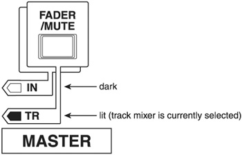
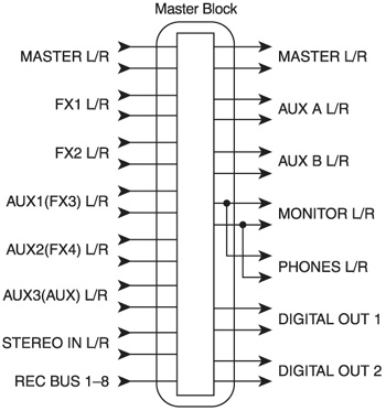
Any effects you apply to this mixer are not part of the recorded signal and can be changed at any time before final mixdown . Routing signals from the Track Mixer is really easy. The track output can be re-routed to facilitate many different applications. For example, you can route the track output back to the recording bus for track bouncing or re-recording. You can also route the tracks to individual outputs for transferring to other multitrack recorders using the Direct Out function. At all times, it is important that you always know which mixer you are working in. There are several ways to keep track of which mixer is selected. One way is to use the FADER/MUTE button, shown in Figure 8.2. Figure 8.2. FADER/MUTE button The FADER/MUTE button allows you to easily switch back and forth between the Input and Track Mixers. When TR is lit, the faders are used to control Track Mixer channels 1-16. This is the setting you will use most often during mixdown. When IN is lit, the faders now control the 10 Input Mixer channels (8 analog and 2 digital), the Stereo Input, plus the 1/3 effects return and the 2/4 effects return. Whenever a new song is created, this feature defaults to the track setting. Another way to switch between the Input and Track Mixer is by using the INPUT SELECT and TRACK SELECT buttons. For example, if you have the FADER/MUTE button set to TR and you need to access the Input Mixer for channel 1, just press the INPUT SELECT button above channel 1. From there, you can easily get back to the Track Mixer for channel 1 by pressing the TRACK SELECT button above channel 1. This does not change the function of the fader. In the above example, when switching to various channel views, the white faders are still active as Track Mixer faders. Master BlockThe Master Block, as seen in Figure 8.3, works like a patch bay. It allows you to determine which signals appear at each of the physical output connections. The Master Block has inputs and outputs just like on a physical patch bay. Each of the inputs can be routed to any of the physical outputs. Figure 8.3. The Master Block can route any of the inputs on the left to any of physical outputs on the right To enter the Master Block, press the EDIT/SOLO button. Use the cursor buttons to move around in the Master Block and use the TIME/VALUE wheel to change the settings. In the diagram above, the MONITOR LR and PHONES LR are connected. The reason is because the signals in the VS-1680 are first routed to the Monitor bus. The Monitor bus is then routed to the Phones output. So in essence, the two knobs (MONITOR and PHONES) are physically connected, with the MONITOR knob taking precedence. That means when you turn the MONITOR knob up or down, you will hear a volume change in your headphones as well. This is the way the VS-1680 is hardwired and cannot be changed. This can be quite frustrating to deal with at times. What I have done to overcome this problem is connect my Stereo Outs to an external mixer, which is connected to my monitors . This bypasses the need to use the MONITOR knob. I control the monitor levels from my external mixer, and that leaves the PHONES and MONITOR knobs on the VS to control the headphone level only. This method gives you more independent control over the Phones and Monitor outputs. This also works nicely when you are recording vocal tracks and you need to turn off your monitors, but still need to hear audio through your headphones. Instead of dealing with the PHONES and MONITOR knobs, you can just turn your monitors off by lowering the volume on the external mixer. Also, if you just need to turn off your monitors while maintaining level in the headphones, you can place an A/B switch between your monitors and your VS-1680's monitor out jacks . Connect one side of the A/B switch to your monitors (A) and leave the other side empty (B). When you need to hear your monitors, select the A setting on the A/B switch. When you need to turn the monitors off, select the B setting. This will also keep you from having to physically power down your monitors to record vocal tracks. |
| < Day Day Up > |