16.3 DATALINK LAYER
|
| < Day Day Up > |
|
16.3 DATALINK LAYER
The physical layer's job is to push the bit stream through a defined interface such as RS232. Before pushing the data, the link has to be activated, and it has to be maintained during the data transfer. After data transfer is complete, the link has to be disconnected. It is possible that one computer may be sending the data very fast, and the receiving computer may not be able to absorb the data at that rate because of its slow processing power. In such a case, the receiving computer has to inform the sending computer to stop transmission for some time and then resume it again. This mechanism is known as flow control, which is the job of the datalink layer. The datalink layer's other function is to ensure error control—this may be in the form of sending acknowledgements or CRC. So, the functions of the data link layer are:
-
Activate the link, maintain the link, and deactivate the link
-
Error detection and control
-
Flow control
The datalink layer's job is to activate the link, maintain the link for data transfer and deactivate the link after the data transfer is complete. Error detection and control, and flow control are also done by the datalink layer.
Some standard datalink layer protocols are high level datalink control (HDLC), link access protocol balanced (LAPB) used in X.25 networks, and link access protocol D (LAPD) used in ISDN.
| Note | In some communication protocols, error detection and flow control are handled by the transport layer. |
16.3.1 High-Level Datalink Control (HDLC)
HDLC is the most widely used datalink layer protocol. Many other datalink layer protocols such as LAPB and LAPD are derived from HDLC. We will briefly describe the HDLC protocol here.
Consider a simple case of two PC's that would like to communicate over an RS232 link. To exchange meaningful data, one of the PCs can take the responsibility of controlling the operations, and the other can operate under the control of the first one. One system can act as a primary node and issue commands; the other acts as a secondary node and gives responses to the commands. Alternatively, both machines can give commands and responses, in which case the node is called the combined node.
Depending on the type of node, the link can be of: (a) unbalanced configuration in which there will be one primary node and one or more secondary nodes; or (b) balanced configuration in which there will be two combined nodes.
The data transfer can be in one of the following three modes:
-
Normal response mode (NRM): This mode is used in unbalanced configuration. The primary node will initiate the data transfer, but the secondary node can send data only on command from the primary node. NRM is used for communication between a host computer and the terminals connected to it.
-
Asynchronous balanced mode (ABM): This mode is used with balanced configuration. A combined node can initiate transmission. ABM is used extensively for point-to-point full-duplex communication.
-
Asynchronous response mode (ARM): This mode is used with unbalanced configuration. The primary node will have the responsibility to initiate the link, error recovery, and logical disconnection, but the secondary node may initiate data transmission without permission from the primary. ARM is rarely used.
The HDLC frame structure is shown in Figure 16.3. The details of the frame structure are as follows:
Flag (8 bits): The flag will have the pattern 01111110. This is to indicate the beginning of the frame. The receiver continuously looks for this pattern to find the beginning of the frame. The frame also ends with the flag so that the receiver can detect the end of frame as well. The actual data may contain the same bit pattern, in which case the frame synchronization is lost. To overcome this, a procedure known as bit stuffing is used—when six ones appear continuously in the data, after five ones, a zero is inserted. At the receiver, after the starting flag is detected, if five ones are detected followed by a zero, that zero is removed. If six ones are detected followed by one zero, then it is taken as the ending flag, and the frame is processed further. However, note that bit stuffing is not foolproof if there are bit errors.
Address (8 bits): This field identifies the secondary node that has to receive the frame. Though an address is not necessary for point-to-point connections, it is included for uniformity. Normally, the address is of 8 bits in length, though higher lengths can be used. The address with all ones is used as the broadcast address.
Control (8 or 16 bits): The control field specifies the type of frame. Three types of frames are defined: information frames which carry data of the HDLC user (layer above HDLC); supervisory frames, which provide automatic repeat request (ARQ) information to request retransmission when data is corrupted; and unnumbered frames, which provide link control functions. Information and supervisory frames contain 3-bit or 7-bit sequence numbers.
Information (variable): This field contains the user information for information frames and unnumbered frames. It should be in multiples of 8 bits.
CRC (16 or 32 bits): Excluding the flags, 16-bit or 32-bit CRC is calculated and kept in this field for error detection.
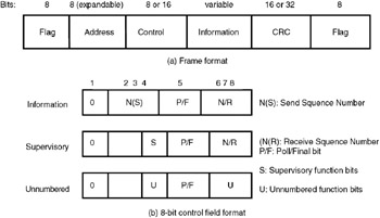
Figure 16.3: HDLC frame format: (a) information frame format, (b) 8-bit control field format
HDLC operation takes three steps: initialization, data transfer, and disconnection.
HDLC protocol is an example of datalink layer protocol. Many datalink layer protocols used in X.25, Frame Relay, and Integrated Services Digital Network (ISDN) are derived from HDLC.
In the initialization phase, the node that wants to set up a link gives a command indicating the mode of transmission (NRM, ABM, or ARM) and whether a 3-bit or 7-bit sequence number is to be used. The other node responds with unnumbered acknowledged frame if it is ready to accept the connection; otherwise it sends a disconnected mode frame. If the initialization has been accepted, a logical connection is established between the two nodes.
In the data transfer mode, data is exchanged between the two nodes using the information frames starting with sequence number 0. To ensure proper flow control and error control, the N(S) and N(R) fields in the control field are used. N(S) is the sequence number and N(R) is the acknowledgement for the information frames received (refer to Figure 16.3b for the formats of the control field.)
Supervisory frames are also used for error control and flow control. The receive ready (RR) frame is used to indicate the last information frame received. Hence, the sender knows that up to that frame, all frames have been received intact. RR frame is used when there is no information frame containing the acknowledgement to be sent. Receive-not-ready (RNR) frame is sent to acknowledge the receipt of frames up to a particular sequence number and also to tell the sender to suspend further transmission. When the node that sent RNR is ready again, it sends an RR frame.
The disconnect phase is initiated by one of the nodes sending a disconnect (DISC) frame. The other node has to respond with an unnumbered acknowledged frame to complete the disconnection phase.
The HDLC protocol is the basis for a number of datalink layer protocols to be discussed in subsequent chapters. Note that in the datalink layer, a number of bytes are put together and a new entity is formed, which is referred to as a frame.
|
| < Day Day Up > |
|
EAN: 2147483647
Pages: 313