Section 5.2. Component Views
5.2. Component ViewsUML uses two views of components, a black-box view and a white-box view. The black-box view shows a component from an outside perspective; the white-box view shows how a component realizes the functionality specified by its provided interfaces. 5.2.1. Black-Box ViewThe black-box view of a component shows the interfaces the component provides, the interfaces it requires, and any other detail necessary to explain the guaranteed behavior of the component. It does not specify anything about the internal implementation of the component. This distinction is central to the concept of replaceable components. 5.2.1.1. Assembly connectorsWhen modeling a black-box view of a component, you represent the provided and required interfaces using assembly connectors. Assembly connectors are illustrated using ball-and-socket icons. To show a required interface, use the socket icon and write the name of the interface near the connector symbol. Figure 5-3 shows a component with two required interfaces. Figure 5-3. Component with two required interfaces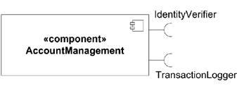 Show a provided interface with the ball half of an assembly connector, again with the name of the interface near the symbol. Figure 5-4 shows a component with a provided interface. Figure 5-4. Component with a provided interface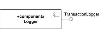 To wire components together, simply connect the matching provided and required interfaces. Component dependencies using assembly connectors provide more details about the actual relationships between components than simple dependency relations. Figure 5-5 shows the same three components from the "Component Dependencies" section, but using assembly connectors. Figure 5-5. Component relationships using assembly connectors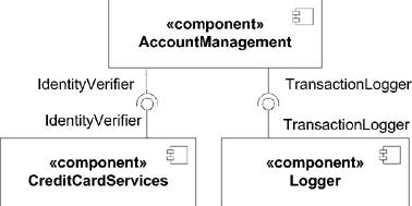 5.2.1.2. Interface dependenciesWhile assembly connectors provide more detail than simple component dependencies, they don't provide detailed information about the interface that is being realized. UML provides a third black-box representation of components using realization and dependency relationships to interfaces. If a component provides an interface, use a realization arrow from the component to the interface. If the component requires an interface, use a dependency arrow from the component to the required interface. Figure 5-6 shows the same three components as Figure 5-2, but with explicit interface dependencies. Figure 5-6. Components with explicit interface dependencies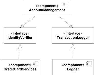 An advantage to the interface dependency style of modeling is that you can attach other modeling elements, such as a state machine or use case, to an interface. This is particularly useful when a component implements a protocol because you can link the provided interface to a protocol state machine to further clarify the component's usage (see "Protocol State Machines" in Chapter 8). 5.2.1.3. Component compartmentsUML also provides a black-box view of components using compartments. You may add a compartment to show provided and required interfaces. Label provided interfaces with the stereotype «provided interfaces» and required interfaces with the stereotype «required interfaces». Figure 5-7 shows the AccountManagement component using compartments to identify the provided and required interfaces. UML suggests an additional compartment, stereotyped «artifacts», that can show which artifacts actually implement a component (typically one or more JARs, DLLs, etc.). Figure 5-8 shows a component with an artifact compartment. Figure 5-7. Interface dependencies in compartment form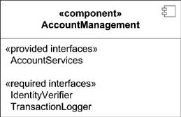 Figure 5-8. A component with an artifacts compartment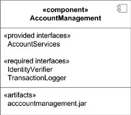 5.2.2. White-Box ViewIn order to provide details about the implementation of a component, UML defines a white-box view. The white-box view shows exactly how a component realizes the interfaces it provides. This is typically done using classes and is illustrated with a class diagram; however a component may delegate some or all of its behavior to other components. 5.2.2.1. Realization compartmentThe simplest white-box view of a component is to add a compartment to the component and list the classifiers that realize it. The compartment should be labeled with the «realizations» stereotype. While this provides more detail than a black-box view, it is of limited use to component developers. Figure 5-9 shows a component with a realizations compartment. 5.2.2.2. Classifier dependenciesTo show the internals of a component, you may show each classifier that realizes a component with a dependency on the component itself. Note that the relationship between the classifiers and the component is a dependency relationship (dashed line, open arrow), not a realization relationship. This notation is useful Figure 5-9. Component with a realizations compartment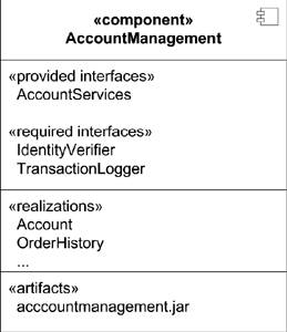 for identifying which classifiers make up a component, but the focus of the diagram is still on the component as a whole. Figure 5-10 shows a white-box view of a component and its constituent classifiers. Figure 5-10. White-box view of AccountManagement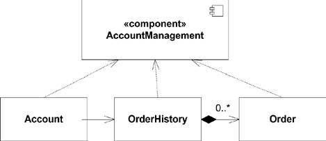 To shift the focus to the structure of the classifiers making up the component, you may show the classifiers inside the component's rectangle. This tends to have the effect of emphasizing the relationships of the classifiers making up the component, and it encourages component encapsulation. Figure 5-11 shows the detailed realization of a component. If the internals of a component are sufficiently complex, it is common to use a separate class diagram to model the details. You can link the new class diagram back to its component using a note. Figure 5-11. Detailed realization of AccountManagement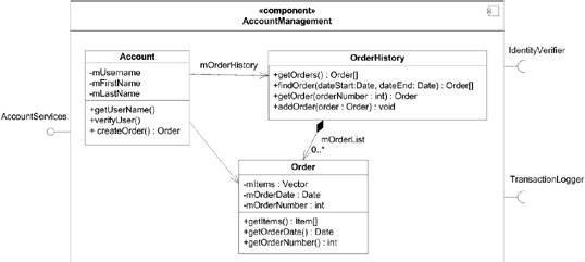 5.2.2.3. Ports and connectorsUML 2.0 introduces the concept of ports to allow you to explicitly identify functionality that is exposed to the outside world. A port groups together related provided and required interfaces and uses connectors to map them to a classifier that realizes the functionality. If a port has both provided and required interfaces, it is called a bidirectional port. A port is shown as a small rectangle on one of the sides of a classifier. An assembly connector (ball and socket) indicates provided and required interfaces. In order to show the realization of functionality, a connector maps the port to an internal classifier. A connector is shown as a solid line with a filled arrow from the port to the classifier. A connector indicates that any messages arriving at the port (typically in the form of method calls) are forwarded to the specified classifier. You can also use connectors from a classifier to a port to show messages being passed through a provided interface. Figure 5-12 shows a white-box view of a component with three ports. Figure 5-12. Component realization with ports and connectors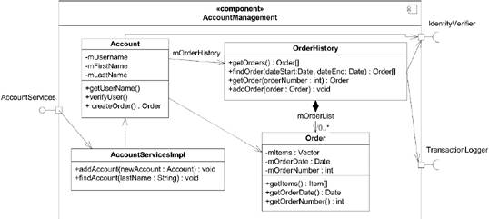 5.2.3. Component StereotypesUML defines several stereotypes that apply specifically to components:
Figure 5-13. A specification component associated with a realization component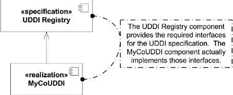
|
EAN: 2147483647
Pages: 132