PNNI Configuration in MSS
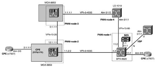
| The objective of this chapter is to bring up the network shown in Figure 10-1. First, the four PNNI nodes are configured to set up the PNNI network. Figure 10-1. PNNI Network
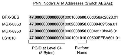
Two external Cisco 7500 routers will be connected through the network using switched virtual circuits (SVCs) and Soft Permanent Virtual Circuits (SPVCs). Connectivity to an RPM-PR-based CPE in the MGX-8850 will also be configured using SPVCs. Your PNNI network is a single peer group (SPG) network at level 64. This means that the first 64 bits or 8 bytes form the peer group ID (PGID). The PNNI node's ATM End System Addresses (AESAs) are chosen so that there's a unique and common peer group ID at level 64. See Figure 10-2. Figure 10-2. PNNI Node's AESAs
For the purposes of this and the following chapters, AESAs with International Code Designator (ICD) format have been chosen, with a bogus ICD of 0x0000. As shown in Figure 10-2, the number in the switch platform name is included in the switch ATM address for ease of identification. |
EAN: 2147483647
Pages: 149